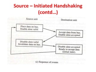
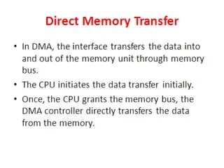
Unit-3 of the document focuses on computer arithmetic, including algorithms for addition, subtraction, multiplication, and division, as well as I/O organization and communication with devices. Key topics include the implementation of these algorithms, methods for input/output data transfer, and a comparison of different I/O bus architectures. The unit emphasizes the need for synchronization between CPU and peripheral devices and describes various modes of data transfer.
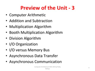

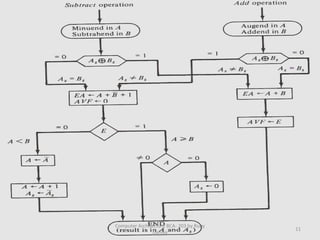
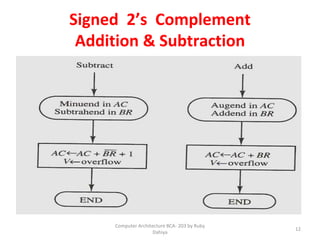
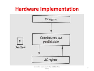

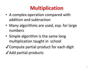
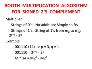
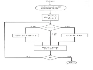
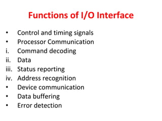
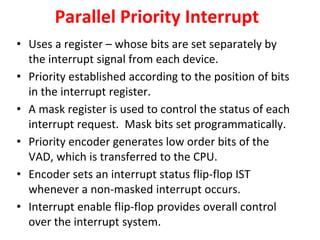
![BOOTH MULTIPLICATION ALGORITHM
FOR SIGNED 2’S COMPLEMENT
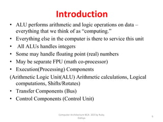
Algorithm:
[1] Subtract multiplicand for the first least
significant 1 in a string of 1’s in the multiplier
[2] Add multiplicand for the first 0 after the
string of 1’s in the multiplier
[3] Partial Product does not change when the
multiplier bit is identical to the previous bit
110010 = -24 + 22 - 21 = -16 + 4 - 2 = -14](https://image.slidesharecdn.com/unit3coa-240221083646-b82d1f02/85/Computer-Organisation-and-Architecture-COA-22-320.jpg)
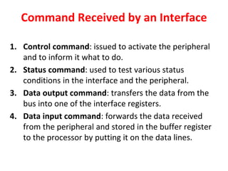
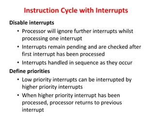
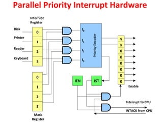
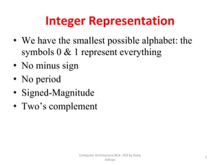
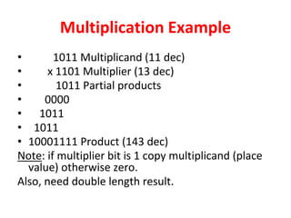
![Interrupt Cycle
• The Interrupt enable flip-flop (IEN) can be set or cleared by
program instructions.
• A programmer can therefore allow interrupts (clear IEN) or
disallow interrupts (set IEN)
• At the end of each instruction cycle the CPU checks IEN and
IST. If either is equal to zero, control continues with the next
instruction. If both = 1, the interrupt is handled.
• Interrupt micro-operations:
SP🡨SP – 1 (Decrement stack pointer)
M[SP] 🡨 PCc Push PC onto stack
INTACK 🡨 1Enable interrupt acknowledge
PC 🡨VAD Transfer vector address to PC
IEN 🡨0 Disable further interrupts
Go to fetch next instruction](https://image.slidesharecdn.com/unit3coa-240221083646-b82d1f02/85/Computer-Organisation-and-Architecture-COA-63-320.jpg)


![Data Structures - Lecture 7 [Linked List]](https://cdn.slidesharecdn.com/ss_thumbnails/lecture-7linkedlists-150121011916-conversion-gate02-thumbnail.jpg?width=640&height=640&fit=bounds)