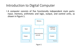
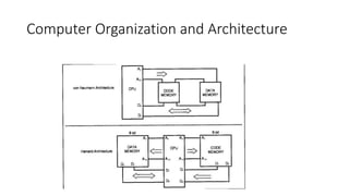
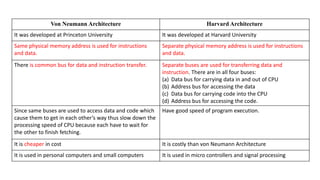
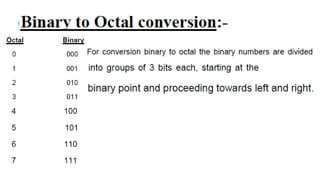
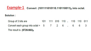
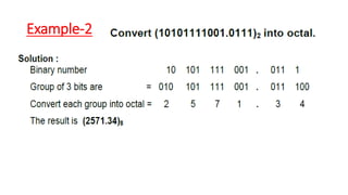
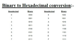
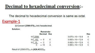
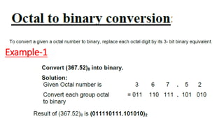
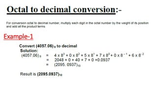
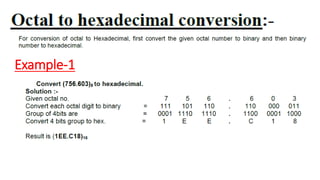
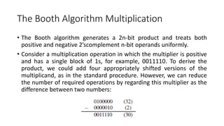
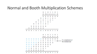
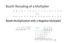
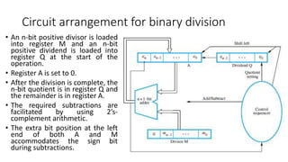
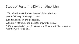
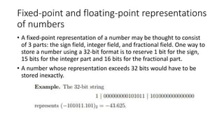
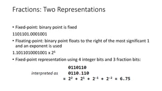
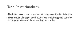
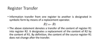
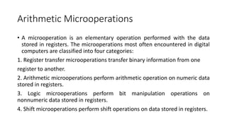
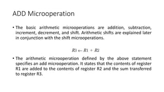
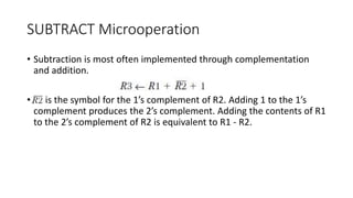
Data representation: Number System, Big Endian and Little Endian, r complement and r-1 complement arithmetic, Unsigned and Signed number representation, Signed Arithmetic- Addition, Subtraction, Multiplication (Booth Algorithm), Division, Barrel Shifter, Fixed and Floating point representation. Block Diagram for Digital Computers: CPU (Registers, ALU, Clock, Control unit), Memory, Memory hierarchy; Different types of memory in brief: Primary (RAM-Static and Dynamic, ROM, DDR2, DDR3, DDR4, NAND Flash, NOR Flash (Samsung memory datasheet) I/O subsystems, Common Bus System (External and Internal Bus: Address Bus, Data Bus and Control Bus); Computer Organization; Computer Architecture; Introduction to Vonn Neumann and Harvard Architecture, Micro operations (Arithmetic, Logical and Shift micro operations using online simulators), Arithmetic Logic and Shift unit (ALU).
2. Introduction to Digital Computer
• A computer consists of five functionally independent main parts:
input, memory, arithmetic and logic, output, and control units, as
shown in Figure 1.
Processor
Control
Arithmetic
and logic
Interconnection
network
Memory
I/O
Output
Input
Figure 1
3. Input Unit
• Computers accept coded information through input units. The most
common input device is the keyboard. Whenever a key is pressed, the
corresponding letter or digit is automatically translated into its
corresponding binary code and transmitted to the processor.
• Many other kinds of input devices for human-computer interaction
are available, including the touchpad, mouse, joystick, and trackball.
Microphones can be used to capture audio input which is then
sampled and converted into digital codes for storage and processing.
Similarly, cameras can be used to capture video input.
4. Memory Unit
• The function of the memory unit is to store programs and data. There are
two classes of storage, called primary and secondary.
• Primary Memory
• Primary memory, also called main memory, is a fast memory that operates at
electronic speeds. Programs must be stored in this memory while they are being
executed.
• The memory consists of a large number of semiconductor storage cells, each capable
of storing one bit of information.
• Instructions and data can be written into or read from the memory under the control
of the processor.
• A memory in which any location can be accessed in a short and fixed amount of time
after specifying its address is called a random-access memory (RAM). The time
required to access one word is called the memory access time. This time is
independent of the location of the word being accessed. It typically ranges from a
few nanoseconds (ns) to about 100 ns for current RAM units.
5. Memory Unit Contd…
• Cache Memory
• As an adjunct to the main memory, a smaller, faster RAM unit, called a cache,
is used to hold sections of a program that are currently being executed, along
with any associated data. The cache is tightly coupled with the processor and
is usually contained on the same integrated-circuit chip. The purpose of the
cache is to facilitate high instruction execution rates.
• At the start of program execution, the cache is empty. All program
instructions and any required data are stored in the main memory. As
execution proceeds, instructions are fetched into the processor chip, and a
copy of each is placed in the cache. When the execution of an instruction
requires data located in the main memory, the data are fetched and copies
are also placed in the cache.
6. Memory Unit Contd…
• Secondary Storage
• Although primary memory is essential, it tends to be expensive and does not
retain information when power is turned off. Thus additional, less expensive,
permanent secondary storage is used when large amounts of data and many
programs have to be stored, particularly for information that is accessed
infrequently.
• Access times for secondary storage are longer than for primary memory. A
wide selection of secondary storage devices is available, including magnetic
disks, optical disks (DVD and CD), and flash memory devices.
7. Arithmetic and Logic Unit
• Most computer operations are executed in the arithmetic and logic
unit (ALU) of the processor. Any arithmetic or logic operation, such as
addition, subtraction, multiplication, division, or comparison of
numbers, is initiated by bringing the required operands into the
processor, where the operation is performed by the ALU. For
example, if two numbers located in the memory are to be added, they
are brought into the processor, and the addition is carried out by the
ALU.
• When operands are brought into the processor, they are stored in
high-speed storage elements called registers. Each register can store
one word of data. Access times to registers are even shorter than
access times to the cache unit on the processor chip.
8. Output Unit
• The output unit is the counterpart of the input unit. Its function is to
send processed results to the outside world. A familiar example of
such a device is a printer. Most printers employ either photocopying
techniques, as in laser printers, or ink jet streams.
9. Control Unit
• The memory, arithmetic and logic, and I/O units store and process
information and perform input and output operations. The operation
of these units must be coordinated in some way. This is the
responsibility of the control unit. The control unit is effectively the
nerve center that sends control signals to other units and senses their
states.
• Data transfers between the processor and the memory are also
managed by the control unit through timing signals.
10. Bus Structure
• The bus shown in Figure 2 is a simple structure that implements the
interconnection network. Only one source/destination pair of units
can use this bus to transfer data at any one time.
Bus
I/O device n
I/O device 1
Memory
Processor
Figure 2
11. I/O Interface for an input device
• The bus consists of three sets of lines used
to carry address, data, and control signals.
I/O device interfaces are connected to
these lines, as shown in Figure 3 for an
input device.
• Each I/O device is assigned a unique set of
addresses for the registers in its interface.
• When the processor places a particular
address on the address lines, it is examined
by the address decoders of all devices on
the bus.
• The device that recognizes this address
responds to the commands issued on the
control lines. The processor uses the
control lines to request either a Read or a
Write operation, and the requested data
are transferred over the data lines.
Figure 3
13. Von Neumann Architecture Harvard Architecture
It was developed at Princeton University It was developed at Harvard University
Same physical memory address is used for instructions
and data.
Separate physical memory address is used for instructions
and data.
There is common bus for data and instruction transfer. Separate buses are used for transferring data and
instruction. There are in all four buses:
(a) Data bus for carrying data in and out of CPU
(b) Address bus for accessing the data
(c) Data bus for carrying code into the CPU
(d) Address bus for accessing the code.
Since same buses are used to access data and code which
cause them to get in each other’s way thus slow down the
processing speed of CPU because each have to wait for
the other to finish fetching.
Have good speed of program execution.
It is cheaper in cost It is costly than von Neumann Architecture
It is used in personal computers and small computers It is used in micro controllers and signal processing
14. There are four types of number systems. They are
1. Decimal number system
2. Binary number system
3. Octal number system
4. Hexadecimal number system
15. 1. Decimal number system
The decimal number system contain ten unique
digits: 0,1,2,3,4,5,6,7,8 and 9.
In decimal system 10 symbols (0-9) are involved, so
the base or radix is 10. e.g. (1245)10
The value attached to the symbol depends on its
location with respect to the decimal point.
16. Example: Place value of Decimal Number
In general,
(MSB) dn dn-1 dn-2 …………… d0 . d -1 d -2 …………d – m (LSB)
is given by
(dn x 10n) + (dn-1 x 10n-1) + (dn-2 x 10n-2) + … + ( d0 x 100) + ( d-1 x
10 -1) + (d-2 x 10 -2) +…+(d -m x 10 –m)
For example:-1 Decimal number- 9256.26
9256.26 = 9 x 1000 + 2 x 100 + 5 x 10 + 6 x 1 + 2 x (1/10) + 6 x ( 1/100)
= 9 x 10³ + 2 x 10² + 5 x 101 + 6 x 100 + 2 x 10⁻¹ + 6 x 10⁻²
17. 2. Binary number system
The binary number system is a positional weighted
system.
The base or radix of this number system is 2.
e.g. (10101)2
The symbols used are 0 and 1.
A single binary digit is called a bit.
18. 3. Octal number system
It is also a positional weighted system.
Its base or radix is 8.
It has 8 independent symbols- 0,1,2,3,4,5,6
and 7.
Its base 8 = 23 (2 to the power 3) , every 3-
bit group of binary can be represented by an
octal digit. e.g.- (14623)8 and (277.13)8
19. 4. Hexa-Decimal number system
It is also a positional weighted system.
Its base or radix is 16.
It has 15 independent symbols-
0,1,2,3,4,5,6,7,9 and 10(A),
11(B),12(C),13(D),14(E),15(F).
0r 0,1,2,3,4,5,6,7,8,9 and 10- A, 11- B,
12- C, 13-D, 14- E and 15-F
e.g.- (14ABF)16 and (12.CD)16
20. CONVERSION FROM ONE NUMBER SYSTEM TO
ANOTHER
• Binary number
conversion to-
1. Octal
2. Decimal
3. Hexa-Decimal
• OCTAL number
conversion to-
1. Binary
2. Decimal
3. Hexa-Decimal
21. CONVERSION FROM ONE NUMBER SYSTEM TO
ANOTHER
•Hexa decimal
number
conversion to-
1. Binary
2. Octal
3. Decimal
•Decimal number
conversion to-
1. Binary
2. Octal
3. Hexa-Decimal
Total 12 types to convert the number system into
each other
22. BINARY NUMBER SYSTEM: Binary to Decimal
• In this method, each binary digit of the number is multiplied by its
positional weight and the product terms are added to obtain decimal
number
Example: 1
43. Complements
• Complements are used in digital computers for simplifying the
subtraction operation and for logical manipulation.
• There are two types of complements for each base r system: the r ’s
complement and the (r — l)’s complement.
• When the value of the base r is substituted in the name, the two
types are referred to as the 2’s and l’s complement for binary
numbers and the 10’s and 9’s complement for decimal numbers.
44. (r — l)’s Complement
• Given a number N in base r having n digits, the (r — l)’s complement
of N is defined as (rn — 1) — N.
• 9’s Complement
• For decimal numbers r = 10 and r — 1 = 9, so the 9’s complement of N is (10n
— 1) — N. Now, 10n represents a number that consists of a single 1 followed
by n 0’s. 10n — 1 is a number represented by n 9’s.
• For example, with n = 4 we have 104 = 10000 and 104 — 1 = 9999. It follows
that the 9’s complement of a decimal number is obtained by subtracting each
digit from 9.
• For example, the 9’s complement of 546700 is 999999 — 546700 = 453299
and the 9’s complement of 12389 is 99999 — 12389 = 87610.
45. 1’s Complement
• For binary numbers, r = 2 and r — 1 = 1, so the 1’s complement of N is (2n
—1) — N. Again, 2n is represented by a binary number that consists of a 1
followed by n 0’s. 2n — 1 is a binary number represented by n 1’s. For
example, with n = 4, we have 24 = (10000)2 and 24 — 1 = (1111)2. Thus the
1’s complement of a binary number is obtained by subtracting each digit
from 1.
• However, the subtraction of a binary digit from 1 causes the bit to change
from 0 to 1 or from 1 to 0. Therefore, the 1’s complement of a binary
number is formed by changing 1’s into 0’s and 0’s into 1’s. For example, the
1’s complement of 1011001 is 0100110 and the 1’s complement of
0001111 is 1110000.
• The (r — l)’s complement of octal or hexadecimal numbers are obtained by
subtracting each digit from 7 or F (decimal 15) respectively.
46. (r ’s) Complement
• 10’s Complement
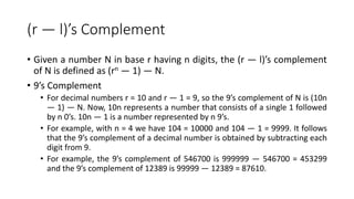
• The r’s complement of an n -digit number N in base r is defined as rn - N for N
≠ 0 and 0 for N = 0. Comparing with the (r - 1)’s complement, we note that
the r’s complement is obtained by adding 1 to the (r - 1)’s complement since
rn - N = [(rn - 1) - N ] + 1. Thus the 10’s complement of the decimal 2389 is
7610 + 1 = 7611 and is obtained by adding 1 to the 9’s complement value.
• The 2’s complement of binary 101100 is 010011 + 1 = 010100 and is obtained
by adding 1 to the l’s complement value.
47. 2’s Complement
• Since 10n is a number represented by a 1 followed by n 0’s, then 10n - N,
which is the 10’s complement of N, can be formed also be leaving all least
significant 0’s unchanged, subtracting the first nonzero least significant
digit from 10, and then subtracting all higher significant digits from 9. The
10’s complement of 246700 is 753300 and is obtained by leaving the two
zeros unchanged, subtracting 7 from 10, and subtracting the other three
digits from 9. Similarly, the 2’s complement can be formed by leaving all
least significant 0’s and the first 1 unchanged, and then replacing 1’s by 0’s
and 0’s by 1’s in all other higher, significant bits.
• The 2’s complement of 1101100 is 0010100 and is obtained by leaving the
two low-order 0’s and the first 1 unchanged, and then replacing 1’s by 0’s
and 0’s by 1’s in the other four most significant bits.
48. Subtraction of Unsigned Numbers
• The subtraction of two n -digit unsigned numbers M N(N 0) in base r
can be done as follows:
1. Add the minuend M to the r’s complement of the subtrahend N. This
performs M + (rn - N) = M - N + rn.
2. If M ≥ N, the sum will produce an end carry rn which is discarded,
and what is left is the result M - N.
3. If M < N, the sum does not produce an end carry and is equal to rn -
(N - M), which is the r’s complement of (N - M). To obtain the answer in
a familiar form, take the r’s complement of the sum and place a
negative sign in front.
49. Example
• Consider, for example, the subtraction 72532 - 13250 = 59282. The
10’s complement of 13250 is 86750. Therefore:
• Now consider an example with M < N. The subtraction 13250 – 72532
produces negative 59282. Using the procedure with complements, we
have
• There is no end carry Answer is negative 59282 = 10’s complement of
40718
50. Integer Representation
• When an integer binary number is positive, the sign is represented by
0 and the magnitude by a positive binary number. When the number
is negative, the sign is represented by 1 but the rest of the number
may be represented in one of three possible ways:
1. Signed-magnitude representation
2. Signed-1’s complement representation
3. Signed 2’s complement representation
• The signed-magnitude representation of a negative number consists
of the magnitude and a negative sign. In the other two
representations, the negative number is represented in either the 1’s
or 2’s complement of its positive value.
51. Example
• Consider the signed number 14 stored in an 8-bit register. +14 is
represented by a sign bit of 0 in the leftmost position followed by the
binary equivalent of 14: 00001110. Note that each of the eight bits of
the register must have a value and therefore 0’s must be inserted in
the most significant positions following the sign bit. Although there is
only one way to represent +14, there are three different ways to
represent -14 with eight bits.
• In signed-magnitude representation 1 0001110
• In signed-1’s complement representation 1 1110001
• In signed-2’s complement representation 1 1110010
52. Arithmetic Addition
• The addition of two numbers in the signed-magnitude system follows
the rules of ordinary arithmetic. If the signs are the same, we add the
two magnitudes and give the sum the common sign. If the signs are
different, we subtract the smaller magnitude from the larger and give
the result the sign of the larger magnitude.
• For example, (+25) + (-37) = -(37 - 25) = 112 and is done by
subtracting the smaller magnitude 25 from the larger magnitude 37
and using the sign of 37 for the sign of the result.
53. The Booth Algorithm Multiplication
• The Booth algorithm generates a 2n-bit product and treats both
positive and negative 2’scomplement n-bit operands uniformly.
• Consider a multiplication operation in which the multiplier is positive
and has a single block of 1s, for example, 0011110. To derive the
product, we could add four appropriately shifted versions of the
multiplicand, as in the standard procedure. However, we can reduce
the number of required operations by regarding this multiplier as the
difference between two numbers:
55. Booth Recoding of a Multiplier
Booth Multiplication with a Negative Multiplier
56. Circuit arrangement for binary division
• An n-bit positive divisor is loaded
into register M and an n-bit
positive dividend is loaded into
register Q at the start of the
operation.
• Register A is set to 0.
• After the division is complete, the
n-bit quotient is in register Q and
the remainder is in register A.
• The required subtractions are
facilitated by using 2’s-
complement arithmetic.
• The extra bit position at the left
end of both A and M
accommodates the sign bit
during subtractions.
57. Steps of Restoring Division Algorithm
• The following algorithm performs restoring division.
Do the following three steps n times:
1. Shift A and Q left one bit position.
2. Subtract M from A, and place the answer back in A.
3. If the sign of A is 1, set q0 to 0 and add M back to A (that is, restore
A); otherwise, set q0 to 1.
59. Fixed-point and floating-point representations
of numbers
• A fixed-point representation of a number may be thought to consist
of 3 parts: the sign field, integer field, and fractional field. One way to
store a number using a 32-bit format is to reserve 1 bit for the sign,
15 bits for the integer part and 16 bits for the fractional part.
• A number whose representation exceeds 32 bits would have to be
stored inexactly.
60. Fractions: Two Representations
• Fixed-point: binary point is fixed
1101101.0001001
• Floating-point: binary point floats to the right of the most significant 1
and an exponent is used
1.1011010001001 x 26
• Fixed-point representation using 4 integer bits and 3 fraction bits:
61. Fixed-Point Numbers
• The binary point is not a part of the representation but is implied
• The number of integer and fraction bits must be agreed upon by
those generating and those reading the number
62. Signed Fixed-Point Numbers
• Negative fractional numbers can be represented two ways:
• Sign/magnitude notation
• Two’s complement notation
• Represent -7.510 using an 8-bit binary representation with 4 integer
bits and 4 fraction bits in Two’s complement:
• +7.5: 01111000
• Invert bits: 10000111
• Add 1 to lsb: 10001000
63. Floating-Point Numbers
• The binary point floats to the right of the most significant digit
• Similar to decimal scientific notation:
• For example, 27310 in scientific notation is
273 = 2.73 ×10²
• In general, a number is written in scientific notation as:
±M ×BE
where:
M= mantissa
B= base
E= exponent
• In the example, M = 2.73, B = 10, and E = 2
64. Floating-Point Numbers
• Convert the decimal number to binary: 22810= 111001002= 1.11001
×27
• Fill in each field of the 32-bit number:
• The sign bit is positive (0)
• The 8 exponent bits represent the value 7
• The remaining 23 bits are the mantissa
65. BIG ENDIAN vs LITTLE ENDIAN
• In a big-endian computer, the two bytes required for the hexadecimal
number 4F52 would be stored as 4F52 in storage.
• For example, if 4F is stored at storage address 1000, 52 will be at
address 1001.
• In a little-endian system, it would be stored as 524F, with 52 at
address 1000 and 4F at 1001.
66. Register Transfer Language
• Digital system design invariably uses a modular approach. The modules are
constructed from such digital components as registers, decoders,
arithmetic elements, and control logic.
• The various modules are interconnected with common data and control
paths to form a digital computer system.
• Digital modules are best defined by the registers they contain and the
operations that are performed on the data stored in them. The operations
executed on data stored in registers are called microoperations.
• A microoperation is an elementary operation performed on the
information stored in one or more registers. The result of the operation
may replace the previous binary information of a register or may be
transferred to another register.
• Examples of microoperations are shift, count, clear, and load.
67. Register Transfer Language Contd…
• The internal hardware organization of a digital computer is best
defined by specifying:
1. The set of registers it contains and their function.
2. The sequence of microoperations performed on the binary
information stored in the registers.
3. The control that initiates the sequence of microoperations.
• The symbolic notation used to describe the microoperation transfers
among registers is called a register transfer language.
68. Introduction to Register
• Computer registers are designated by capital letters (sometimes
followed by numerals) to denote the function of the register. For
example, the register that holds an address for the memory unit is
usually called a memory address register and is designated by the
name MAR. Other designations for registers are PC (for program
counter), IR (for instruction register, and R1 (for processor register).
69. Register Representation
• The most common way to represent a register is by a rectangular box
with the name of the register inside, as in Figure 4 (a).
• The individual bits can be distinguished as in Figure 4(b).
• The numbering of bits in a 16-bit register can be marked on top of the
box as shown in Figure 4(c).
• A 16-bit register is partitioned into two parts is shown in Figure 4(d).
• Bits 0 through 7 are assigned the symbol L (for low byte) and bits 8
through 15 are assigned the symbol H (for high byte). The name of
the 16-bit register is PC. The symbol PC(0–7) or PC(L) refers to the
low-order byte and PC(8–15) or PC(H ) to the high-order byte.
71. Register Transfer
• Information transfer from one register to another is designated in
symbolic form by means of a replacement operator.
• The above statement denotes a transfer of the content of register R1
into register R2. It designates a replacement of the content of R2 by
the content of R1. By definition, the content of the source register R1
does not change after the transfer.
72. Arithmetic Microoperations
• A microoperation is an elementary operation performed with the data
stored in registers. The microoperations most often encountered in digital
computers are classified into four categories:
1. Register transfer microoperations transfer binary information from one
register to another.
2. Arithmetic microoperations perform arithmetic operation on numeric data
stored in registers.
3. Logic microoperations perform bit manipulation operations on
nonnumeric data stored in registers.
4. Shift microoperations perform shift operations on data stored in registers.
73. ADD Microoperation
• The basic arithmetic microoperations are addition, subtraction,
increment, decrement, and shift. Arithmetic shifts are explained later
in conjunction with the shift microoperations.
• The arithmetic microoperation defined by the above statement
specifies an add microoperation. It states that the contents of register
R1 are added to the contents of register R2 and the sum transferred
to register R3.
74. SUBTRACT Microoperation
• Subtraction is most often implemented through complementation
and addition.
• is the symbol for the 1’s complement of R2. Adding 1 to the 1’s
complement produces the 2’s complement. Adding the contents of R1
to the 2’s complement of R2 is equivalent to R1 - R2.
76. Logic Microoperations
• Logic microoperations specify binary operations for strings of bits
stored in registers. These operations consider each bit of the register
separately and treat them as binary variables. For example, the
exclusive-OR microoperation with the contents of two registers R1
and R2 is symbolized by the statement
78. Shift Microoperations
• Shift microoperations are used for serial transfer of data.
• The contents of a register can be shifted to the left or the right.
• During a shift-left operation the serial input transfers a bit into the
rightmost position. During a shift-right operation the serial input
transfers a bit into the leftmost position.
• There are three types of shifts: logical, circular, and arithmetic.
79. logical shift
• A logical shift is one that transfers 0 through the serial input.
• For Example:
• are two microoperations that specify a 1-bit shift to the left of the
content of register R1 and a 1-bit shift to the right of the content of
register R2. The register symbol must be the same on both sides of
the arrow. The bit transferred to the end position through the serial
input is assumed to be 0 during a logical shift.
80. circular shift
• The circular shift (also known as a rotate operation) circulates the bits
of the register around the two ends without loss of information. This
is accomplished by connecting the serial output of the shift register to
its serial input.
81. arithmetic shift
• An arithmetic shift is a microoperation that shifts a signed binary
number to the left or right. An arithmetic shift-left multiplies a signed
binary number by 2. An arithmetic shift-right divides the number by
2.
• The leftmost bit in a register holds the sign bit, and the remaining bits
hold the number. The sign bit is 0 for positive and 1 for negative.
Negative numbers are in 2’s complement form.