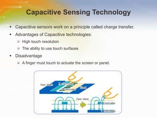
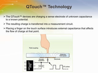
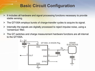
Introducing   to   QTouch™   Chip   QT100A Source:   Quantum   Research   Group
Introduction Purpose To   introduce   Charge-Transfer   QTouch™   technology   and   the   QT100A   device Outline QTouch   Technology   Overview Features   &   Application Basic   Circuit   Configuration Internal   operations Content 15   pages
Capacitive Sensing Technology Capacitive sensors work on a principle called charge transfer. Advantages of Capacitive technologies: High touch resolution The ability to use touch surfaces Disadvantage A finger must touch to actuate the screen or panel.
QTouch™ Technology The   QTouch™   devices   are   charging   a   sense   electrode   of   unknown   capacitance   to   a   known   potential.   The   resulting   charge   is   transferred   into   a   measurement   circuit.   Placing   a   finger   on   the   touch   surface   introduces   external   capacitance   that   affects   the   flow   of   charge   at   that   point.
QTouch™ Technology  cont’d QTouch™   sensors   can   drive   single   or   multiple   keys. QTouch™   technology   can   be   deployed   in   two   ways,   normal   or   ‘touch’   mode   and   high-sensitivity   or   ‘proximity’   mode.   QTouch™   sensors   use   spread-spectrum   modulation   and   sparse,   randomized   charging   pulses   with   long   delays   between   bursts.   QTouch™   devices   feature   automatic   drift   compensation   to   account   for   slow   changes   due   to   ageing   or   changing   environmental   conditions.
QT100A:   Charge-Transfer   QTouch™   Chip   Features Self-calibrating on power-up  Sensitivity easily adjusted  Consensus filter for noise immunity  Auto-recalibration timeout  HeartBeat™ health indicator on output  Only a few passive external parts required  RoHS compliant 6-WSON package Applications Home appliances Toys Lighting controls Stereo systems and TV
Basic Circuit Configuration It includes all hardware and signal processing functions necessary to provide stable sensing. The QT100A employs bursts of charge-transfer cycles to acquire its signal. Internally the signals are digitally processed to reject impulse noise, using a 'consensus' filter. The QT switches and charge measurement hardware functions are all internal to the QT100A.
Sensitivity Increasing Sensitivity using a larger electrode reducing panel thickness increasing the value of Cs Decreasing Sensitivity decreasing Cs
Sensitivity Differences between QT100 and QT100A
Run Modes The   QT100A   has   three   running   modes   which   depend   on   the   logic   level   applied   to   the   SYNC   pin. Fast   Mode   (SYNC   =   1): The   QT100A   runs   at   maximum   speed   at   the   expense   of   increased   current   consumption. Fast   mode   is   useful   when   speed   of   response   is   the   prime   design   requirement. Low   Power   Mode   (SYNC   =   0) It   sleeps   for   approximately   85ms   at   the   end   of   each   burst,   saving   power   but   slowing   response On   detecting   a   possible   key   touch,   it   temporarily   switches   to   Fast   mode   then   returns   to   LP   mode   after   the   key   touch   is   resolved. Sync   Mode Sync   mode   can   synchronize   multiple   QT100A   devices   to   each   other   to   prevent   cross-interference It   can   be   used   to   enhance   noise   immunity   from   low   frequency   sources   such   as   50Hz   or   60Hz   mains   signals.
Drift Compensation Signal drift can occur because of changes in Cx and Cs over time. Drift compensation is performed by making the reference level track the raw signal at a slow rate. Once an object is sensed, the drift compensation mechanism ceases. The QT100A's compensates faster for decreasing signals than for increasing signals.
Output Features The output of the QT100A is active-high upon detection. The QT100A output has a HeartBeat™ ‘health’ indicator superimposed on it in all modes. The HeartBeat indicator can be sampled by using a pull-up resistor on the OUT pin. The pulses will only be visible when the chip is not detecting a touch. Getting HeartBeat pulses with a pull-up resistor
Evaluation Board  The E100S evaluation board  has been developed to show the capabilities of the QT100 and the QT100A. The board demonstrates the chip in a typical application; a simple through-panel single-switch. The E100S illustrates how a QTouch™ solution requires only a very simple circuit design and a minimum of external components.
Application Information LED bypassing to prevent key interference
Additional Resource For   ordering   the   QT100A ,   please   click   the   part   list   or Call   our   sales   hotline For   additional   inquires   contact   our   technical   service   hotline For   more   product   information   go   to http://www.qprox.com/products/Page-16035/QT100A.html

Introducing to QTouch™ Chip QT100A

  • 1.
    Introducing to QTouch™ Chip QT100A Source: Quantum Research Group
  • 2.
    Introduction Purpose To introduce Charge-Transfer QTouch™ technology and the QT100A device Outline QTouch Technology Overview Features & Application Basic Circuit Configuration Internal operations Content 15 pages
  • 3.
    Capacitive Sensing TechnologyCapacitive sensors work on a principle called charge transfer. Advantages of Capacitive technologies: High touch resolution The ability to use touch surfaces Disadvantage A finger must touch to actuate the screen or panel.
  • 4.
    QTouch™ Technology The QTouch™ devices are charging a sense electrode of unknown capacitance to a known potential. The resulting charge is transferred into a measurement circuit. Placing a finger on the touch surface introduces external capacitance that affects the flow of charge at that point.
  • 5.
    QTouch™ Technology cont’d QTouch™ sensors can drive single or multiple keys. QTouch™ technology can be deployed in two ways, normal or ‘touch’ mode and high-sensitivity or ‘proximity’ mode. QTouch™ sensors use spread-spectrum modulation and sparse, randomized charging pulses with long delays between bursts. QTouch™ devices feature automatic drift compensation to account for slow changes due to ageing or changing environmental conditions.
  • 6.
    QT100A: Charge-Transfer QTouch™ Chip Features Self-calibrating on power-up Sensitivity easily adjusted Consensus filter for noise immunity Auto-recalibration timeout HeartBeat™ health indicator on output Only a few passive external parts required RoHS compliant 6-WSON package Applications Home appliances Toys Lighting controls Stereo systems and TV
  • 7.
    Basic Circuit ConfigurationIt includes all hardware and signal processing functions necessary to provide stable sensing. The QT100A employs bursts of charge-transfer cycles to acquire its signal. Internally the signals are digitally processed to reject impulse noise, using a 'consensus' filter. The QT switches and charge measurement hardware functions are all internal to the QT100A.
  • 8.
    Sensitivity Increasing Sensitivityusing a larger electrode reducing panel thickness increasing the value of Cs Decreasing Sensitivity decreasing Cs
  • 9.
  • 10.
    Run Modes The QT100A has three running modes which depend on the logic level applied to the SYNC pin. Fast Mode (SYNC = 1): The QT100A runs at maximum speed at the expense of increased current consumption. Fast mode is useful when speed of response is the prime design requirement. Low Power Mode (SYNC = 0) It sleeps for approximately 85ms at the end of each burst, saving power but slowing response On detecting a possible key touch, it temporarily switches to Fast mode then returns to LP mode after the key touch is resolved. Sync Mode Sync mode can synchronize multiple QT100A devices to each other to prevent cross-interference It can be used to enhance noise immunity from low frequency sources such as 50Hz or 60Hz mains signals.
  • 11.
    Drift Compensation Signaldrift can occur because of changes in Cx and Cs over time. Drift compensation is performed by making the reference level track the raw signal at a slow rate. Once an object is sensed, the drift compensation mechanism ceases. The QT100A's compensates faster for decreasing signals than for increasing signals.
  • 12.
    Output Features Theoutput of the QT100A is active-high upon detection. The QT100A output has a HeartBeat™ ‘health’ indicator superimposed on it in all modes. The HeartBeat indicator can be sampled by using a pull-up resistor on the OUT pin. The pulses will only be visible when the chip is not detecting a touch. Getting HeartBeat pulses with a pull-up resistor
  • 13.
    Evaluation Board The E100S evaluation board has been developed to show the capabilities of the QT100 and the QT100A. The board demonstrates the chip in a typical application; a simple through-panel single-switch. The E100S illustrates how a QTouch™ solution requires only a very simple circuit design and a minimum of external components.
  • 14.
    Application Information LEDbypassing to prevent key interference
  • 15.
    Additional Resource For ordering the QT100A , please click the part list or Call our sales hotline For additional inquires contact our technical service hotline For more product information go to http://www.qprox.com/products/Page-16035/QT100A.html

Editor's Notes

  • #3 Welcome to the training module on Introducing to QTouch™ Chip QT100A . This training module introduces the Charge-Transfer QTouch™ technology and the QT100A device.
  • #4 A capacitive touch control with a touch screen uses a surface coated with a conductive material such as indium tin oxide that can store a charge. The material conducts an electrical current across the panel along the X- and Y-axes. When touched by something conductive, such as a finger, that controlled field is altered and the location of the touch along the horizontal and vertical axes can be determined. Capacitive technologies have a number of advantages, including high-touch resolution and the ability to use touch surfaces that provide high image clarity, and resistance to dirt, grease or moisture. One disadvantage of capacitive technology is that to actuate the screen or panel, a finger must touch it. This is unlike some other technologies such as resistive controls or acoustic signal processing systems that can be activated with a pen, a stylus, a corner of a credit card or other item. Some experts also say that traditional capacitive systems are susceptible to electrostatic discharge and electromagnetic interference.
  • #5 The QTouch™ devices are charging a sense electrode of unknown capacitance to a known potential. The electrode is typically a copper area on a printed circuit board. The resulting charge is transferred into a measurement circuit. By measuring the charge after one or more charge-and-transfer cycles, the capacitance of the sense plate can be determined. Placing a finger on the touch surface introduces external capacitance that affects the flow of charge at that point. This registers as a touch. QTouch™ microcontrollers can also be set up to detect the proximity of a finger, rather than absolute touch. These ICs are ideal for simple, inexpensive touch controls in almost any product. The devices require only an external sampling capacitor and an electrode to operate.
  • #6 QTouch™ sensors can drive single or multiple keys. Where multiple keys are used, each key can be set for an individual sensitivity level. Keys of different sizes and shapes can be used to meet both functional and aesthetic requirements. This technology can be deployed in two ways, normal or ‘touch’ mode and high-sensitivity or ‘proximity’ mode. The highly sensitive charge transfer proximity sensing is used to detect an end-user’s approaching finger, and have the user interface interrupt the electronic equipment or electrical appliance to initiate a system function. QTouch™ sensors use spread-spectrum modulation and sparse, randomized charging pulses with long delays between bursts. The benefits of this approach include lower cross-sensor interference, reduced RF emissions and susceptibility, and low power consumption.  QTouch™ devices feature automatic drift compensation to account for slow changes due to ageing or changing environmental conditions .
  • #7 The QT100A charge-transfer touch sensor is a self-contained digital IC capable of detecting near-proximity or touch. It will project a touch or proximity field through any dielectric like glass, plastic, stone, ceramic, and even most kinds of wood. It can also turn small metal-bearing objects into intrinsic sensors, making them responsive to proximity or touch. This capability, coupled with its ability to self-calibrate, can lead to entirely new product concepts. This device can also project a proximity field to several centimetres with the proper electrode and circuit design. The QT100A is designed to replace the QT100 with almost identical electrical characteristics. The QT100A is designed specifically for human interfaces, like control panels, appliances, toys, lighting controls, or anywhere a mechanical switch or button may be found.
  • #8 The QT100A is a digital burst mode charge-transfer (QT) sensor designed specifically for touch controls; it includes all hardware and signal processing functions necessary to provide stable sensing under a wide variety of changing conditions. The figure shows a basic circuit using the device. Only a single low cost capacitor is required for operation. The QT100A employs bursts of charge-transfer cycles to acquire its signal. In all cases the rule Cs>Cx must be observed for proper operation; a typical load capacitance (Cx) ranges from 2-20pF while Cs is usually from 2-50nF.
  • #9 The QT100A is designed to replace the QT100 with almost identical electrical characteristics. The sensitivity on the QT100A is a function of things like the value of Cs, electrode size and capacitance, electrode shape and orientation, the composition and aspect of the object to be sensed, the thickness and composition of any overlaying panel material, and the degree of ground coupling of both sensor and object.
  • #10 The sensitivity of the QT100 and QT100A is virtually identical in certain voltage ranges but may require a change of the Cs capacitor outside this range. In the three charts, the vertical axis represents the amount of Cx required to trigger the chip and thus higher amounts of Cx on this graph mean less sensitivity. The QT100A exhibits remarkably similar performance to the QT100 in all circuits when Vdd is at or below 3.5V. Above 3.5V operation, the QT100A based touch button will appear to be increasingly more sensitive relative to the QT100. To compensate, the Cs capacitor can be adjusted in value. It is advisable to reduce the value of Cs so that the touch button is not overly sensitive.
  • #11 The QT100A has three running modes which depend on the logic level applied to the SYNC pin. The QT100A runs in Fast mode if the SYNC pin is permanently high. The QT100A runs in Low Power (LP) mode if the SYNC pin is held low. It is possible to synchronize the device to an external clock source by placing an appropriate waveform on the SYNC pin. In fast mode, the device runs at maximum speed at the expense of increased current consumption. In low power mode, it sleeps for approximately 85ms at the end of each burst, saving power but slowing response. Sync mode can synchronize multiple QT100A devices to each other to prevent cross-interference, or it can be used to enhance noise immunity from low frequency sources such as 50Hz or 60Hz mains signals.
  • #12 Signal drift can occur because of changes in Cx and Cs over time. It is crucial that drift be compensated for, otherwise false detections, non-detections, and sensitivity shifts will follow. Drift compensation is performed by making the reference level track the raw signal at a slow rate, but only while there is no detection in effect. The rate of adjustment must be performed slowly, otherwise legitimate detections could be ignored. Once an object is sensed, the drift compensation mechanism ceases since the signal is legitimately high, and therefore should not cause the reference level to change. The QT100A's drift compensation is 'asymmetric'; the reference level drift-compensates in one direction faster than it does in the other. Specifically, it compensates faster for decreasing signals than for increasing signals.
  • #13 The output of the QT100A is active-high upon detection. The output will remain active-high for the duration of the detection, or until the Max On-duration expires, whichever occurs first. If a Max On-duration timeout occurs first, the sensor performs a full recalibration and the output becomes inactive (low) until the next detection. The QT100A output has a HeartBeat™ ‘health’ indicator superimposed on it in all modes. This output state can be used to determine that the sensor is operating properly, or it can be ignored, using one of several simple methods. The HeartBeat indicator can be sampled by using a pull-up resistor on the OUT pin. The pulses will only be visible when the chip is not detecting a touch.
  • #14 The E100S evaluation board has been developed to show the capabilities of the QT100 and the QT100A. The board demonstrates the chip in a typical application; a simple through-panel single-switch. The E100S illustrates how a QTouch™ solution requires only a very simple circuit design and a minimum of external components.
  • #15 Here shows application information of LED bypassing to prevent key interference . Spot indication can be achieved by using LEDs mounted on the PCB near or even in the middle of electrodes. The easiest solution is to bypass all switched LED terminals with a capacitor to circuit ground. LEDs near a key or its traces whose terminals can float like this open collector driver require a bypass capacitor from the floating node to ground to swamp the effects of variable cross capacitance. The bypass capacitor does not have to be near the LED to be effective.
  • #16 Thank you for taking the time to view this presentation on Introducing to QTouch™ Chip QT100A. If you would like to learn more or go on to purchase some of these devices, you may either click on the part list link, or simple call our sales hotline. For more technical information you may either visit the Quantum Research Group, or if you would prefer to speak to someone live, please call our hotline number, or even use our ‘live chat’ online facility.