1. Car Parking Guard Circuit Using Infrared Sensor
By-Aakash Soni (2k19/ec/004)
Aastik (2k19/ec/005)
Introduction: While parking the car the driver should be more careful because he cannot see the back
of the car while parking or taking reverse, if there is any obstacle and ran over it might be get damage to the
car. Our project will help the person in the driving seat and give alarm if there is any obstacle or a wall while
parking or while driving in reverse.
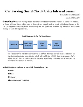
Block Diagram of Car Parking Guard:
The IR sensor will detect the obstacle with in 100cm, if there is any obstacle it will sense and
give information to the tone detector which will enable the LM555 timer to generate a PWM
for the buzzer. The LM555 will generate the pulse which helps to buzz the buzzer so driver can
understand that there is an obstacle.
Main Component used and to learn their functioning are as:
• LM567
• LM555
• IR Sensor
• Photo Darlington Transistor
2. Circuit Diagram of Car Parking Guard:
Brief Explanation:
• The reverse indicator light supply is given to the 7805 regulator to give 5v to the rest of
the circuit. The diode D6 is used to eliminate the reverse current and wrong supply
polarity.
• When the car is driving in reverse the car battery will provide DC supply the reverse
light indicator at the back of the car when this supply came to the reverse light indicator
the circuit will have the power supply.7805 will regulate the DC voltage to 5V and give
to the IR Sensors through the transistor with 20 KHz modulating frequency of the
LM567 (TONE DETECTOR) available at Pin5. The resistor R1 will resists the IR senor
current. At this point the pin8 of LM567 is high which will enable the LM555 timer
operating in astable multivibrator mode. The output of the timer is enabled which can be
assured by the LED (blinking) and also buzzer will beeps at determined rate given by the
resistors R6, R7 and capacitor C7. The timer output also is given to the lamp through a
transistor. The lamp will blink as a warning signal because of the PWM signal generated
by the timer, transistor will work as a switch and resistor R10 will limit the current. This
condition is maintained until the 20 KHz signal is received by the pin3 of the LM567.
• The above condition is when there is no obstacle in the path of the car while taking
reverse. If there is a obstacle the IR beam will radiate back to the IR sensor and the
20KHz modulated signal is given to the pin3 of LM567 through photo Darlington
transistor, at this point the pin8 of the LM567 is turned to low and also gets locked to
detect the 20Khz signal. By this the LM555 is turned low and disabled by this the led
will remain lighting and buzzer makes the continuous sound to alert the driver.
We will perform this on Hardware
• Excepted time taken for this around 2 months