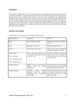
Filename: Floodline Groundhog - Mk2 - Rev 1
. . . . . . .
Floodline
LeakandFloodDetectionSystems
Groundhog MK 2
Instruction Manual
Tel: +44 (0)191 490 1547
Fax: +44 (0)191 477 5371
Email: northernsales@thorneandderrick.co.uk
Website: www.heattracing.co.uk
www.thorneanderrick.co.uk
Filename: Floodline Groundhog - Mk2 - Rev 1 2
Contents
Contents ....................................................................................................2
Introduction................................................................................................3
Indicators and Controls..............................................................................3
Operation...................................................................................................4
Leak Alarm ................................................................................................4
System Fault Alarm ...................................................................................4
Reset .........................................................................................................4
Sensitivity Setting ......................................................................................5
Connection Details ....................................................................................5
Installation .................................................................................................6
Power Supply ............................................................................................6
Dimensions................................................................................................6
Weight........................................................................................................6
Filename: Floodline Groundhog - Mk2 - Rev 1 3
Introduction
The Floodline Groundhog Mk II is a self-contained single zone leak detection system, which can be mounted
vertically or horizontally. It will generate a leak alarm when any conductive liquid is present between the two
detection probes (and or auxiliary sensor device). The unit can be connected to any control/building
management system that has the facility to accept volt-free contacts. The control/building management system
may also be able to supply power to the unit (see latter section on supply details). Connection to the unit is via
the site wire-able terminals, which are provided within the terminal compartment of the unit. Additional
Floodline point sensor/s (horizontal or vertical) or leak detection tape/cable can be slaved off the groundhog. The
groundhog unit is mounted onto a stainless steel guard plate which assists fixing, stability and provides
protection from physical abuse.
Indicators and Controls
The table below lists the indicators and control provided by the unit.
Indicator/Control Description Function
Power Green LED on top of unit. Illuminate when power is supplied to
the unit.
Leak Red LED on top of unit. Flashes when leak detected.
System Yellow LED on top of unit. Flashes when system fault detected
(sensor disconnected or shorted).
Alarm Outputs
(Com = Common)
(N/C = Normally Closed)
(N/0 = Normally Open)
24Vdc 1Amp relay provides volt-
free contact for the output terminals
(Com. N/C N/O)
The relay is normally active and the
power to the relay is switched off
when an alarm is active or if power
to the unit is lost.
M A Reset Switch Manual/ Auto reset select switch,
position within the terminal
compartment.
Set the unit reset to auto or manual
in auto mode the unit will reset when
the alarm event has been cleared.
Sensitivity Setting Sensitivity Setting Trimpot
positioned within the terminal
compartment. Can be set between
30k and 300k
Sets the leak threshold level. When
the resistance between the sensor
probes falls below this level a leak
alarm is generated.
Filename: Floodline Groundhog - Mk2 - Rev 1 4
Operation
When power is supplied to the unit the green “power on” LED will illuminate, and provided no conductive liquid
is present, or the detection probes are not shorted or disconnected, no further indicators will show. The Floodline
system works from the principle that water, or other conductive liquid must touch one or more of the sensors for
an alarm to be activated.
The system essentially detects differences in resistance between it sensor probes (or auxiliary sensor) . The leak
detection and system fault alarms are activated when the resistance falls between, below or above set limits as
detailed below.
• 0Ω to 1kΩ Short circuit causing SYSTEM FAULT alarm
• 1kΩ to 300kΩ * Water detection casing LEAK alarm
• 300kΩ* to 1.25MΩ:- SAFE - no alarm,
• above 1.25MΩ Open circuit causing SYSTEM FAULT alarm
*Or less according to sensitivity setting - see later
Leak Alarm
When a conductive liquid touches the probes (and/or other slaved leak detection device) a “leak alarm” will be
activated, the red LED will flash and the volt-free contact relay will deactivate. There is a time delay of 3
seconds between water touching the probes/sensor and the alarm being activated.
System Fault Alarm
When the sensor connected to the sensor terminals with in the terminal compartment becomes disconnected of
any of the sensors are shorted a “system alarm” will be activated, the yellow LED will flash and the volt-free
contact relay will deactivate. There is a time delay of 3 seconds between the sensor/s being disconnected or
shorted and the alarm being activated.
Reset
The unit is available with two reset options which are set via the M/A switch located within the cable
compartment and is positioned just above the auxiliary sensor connection terminals:
A (Automatic) - Once the leak has been dealt with the unit will reset.
M(Manual). - Has to be manually reset alarm once condition removed. To reset the unit either switch the
M/A switch from M to A then back to M or switch the power off and then back on.
Note: If using leak detection tape then the tape will take time to dry out. The time it takes the
tape to dry out will depend on the nature of the leak and the local conditions (Temperature, air
movement etc) and the sensitivity setting of the unit.
Filename: Floodline Groundhog - Mk2 - Rev 1 5
Sensitivity Setting
The sensitivity setting trimpot is used to set the leak alarm threshold of the unit. The range of the sensitivity is
30k to 300k and is set at 300k when leveling the factory. This setting should not be change if only the built in
probes of point sensors are used. The sensitivity only needs to be change if the cable or tape sensor is used as an
auxiliary sensor. Site conditions and the length of tape used then would determine the setting.
Connection Details
Remove the lid from the terminal compartment and you will see 2 sets of terminal. The set of 6 connections in 2
groups of 3 is for power input and alarm contact outputs. The set of 2 connections is for connecting any auxiliary
sensor. The function and identification of each is given in the table below.
TERMINAL ID FUNCTION
Alarm Relay
Com Relay Output (volt-free) Common
N/C Relay Output (volt-free)
Normally Closed
N/0 Relay Output (volt-free)
Normally Open
Power In
0V 0 Volt D.C./A.C.
24V 24 Volt D.C./A.C Positive
12V 12 Volt D.C./A.C Positive
Sensor
+ Auxiliary Sensor connection +
- Auxiliary Sensor connection +
Replace the cover to the plug and place the plug into the unit’s socket. The Floodline Groundhog is now ready
for use. Connect any additional sensors to the unit and check for correct operation by either placing the sensor
probes in water or shorting them together.
The connection wire can be standard PVC/PVC 7/0.2 alarm/comms. cable
provided the voltage and current rating of the cable is to the standard need,
for the voltage/current being switch by the volt-free contacts
Filename: Floodline Groundhog - Mk2 - Rev 1 6
Installation
The groundhog (s)(& associated devices if used) should be placed in a position where liquid is likely to escape or
gather. Site conditions, extent of area to be covered and the estimated degree of risk will determine the number
of units used.
Further design guidelines can be found in the standard Floodline brochure. Floodline 4/8/16 Zone Installation
manual or Andel’s web site WWW.ANDEL.CO.UK
Power Supply
SUPPLY VOLTAGE SUPPPLY CURRENT (STANDBY) SUPPLY CURRENT
(LEAK DETECTED)
12Vac 32mA 27mA
12Vdc 32mA 27mA
24Vac 32mA 27mA
24Vdc 32mA 27mA
Dimensions
Length = 130mm Width = 90mm, Height = 37mm.
Weight
230g

Andel Floodline - Instruction Manual

  • 1.
    Filename: Floodline Groundhog- Mk2 - Rev 1 . . . . . . . Floodline LeakandFloodDetectionSystems Groundhog MK 2 Instruction Manual Tel: +44 (0)191 490 1547 Fax: +44 (0)191 477 5371 Email: northernsales@thorneandderrick.co.uk Website: www.heattracing.co.uk www.thorneanderrick.co.uk
  • 2.
    Filename: Floodline Groundhog- Mk2 - Rev 1 2 Contents Contents ....................................................................................................2 Introduction................................................................................................3 Indicators and Controls..............................................................................3 Operation...................................................................................................4 Leak Alarm ................................................................................................4 System Fault Alarm ...................................................................................4 Reset .........................................................................................................4 Sensitivity Setting ......................................................................................5 Connection Details ....................................................................................5 Installation .................................................................................................6 Power Supply ............................................................................................6 Dimensions................................................................................................6 Weight........................................................................................................6
  • 3.
    Filename: Floodline Groundhog- Mk2 - Rev 1 3 Introduction The Floodline Groundhog Mk II is a self-contained single zone leak detection system, which can be mounted vertically or horizontally. It will generate a leak alarm when any conductive liquid is present between the two detection probes (and or auxiliary sensor device). The unit can be connected to any control/building management system that has the facility to accept volt-free contacts. The control/building management system may also be able to supply power to the unit (see latter section on supply details). Connection to the unit is via the site wire-able terminals, which are provided within the terminal compartment of the unit. Additional Floodline point sensor/s (horizontal or vertical) or leak detection tape/cable can be slaved off the groundhog. The groundhog unit is mounted onto a stainless steel guard plate which assists fixing, stability and provides protection from physical abuse. Indicators and Controls The table below lists the indicators and control provided by the unit. Indicator/Control Description Function Power Green LED on top of unit. Illuminate when power is supplied to the unit. Leak Red LED on top of unit. Flashes when leak detected. System Yellow LED on top of unit. Flashes when system fault detected (sensor disconnected or shorted). Alarm Outputs (Com = Common) (N/C = Normally Closed) (N/0 = Normally Open) 24Vdc 1Amp relay provides volt- free contact for the output terminals (Com. N/C N/O) The relay is normally active and the power to the relay is switched off when an alarm is active or if power to the unit is lost. M A Reset Switch Manual/ Auto reset select switch, position within the terminal compartment. Set the unit reset to auto or manual in auto mode the unit will reset when the alarm event has been cleared. Sensitivity Setting Sensitivity Setting Trimpot positioned within the terminal compartment. Can be set between 30k and 300k Sets the leak threshold level. When the resistance between the sensor probes falls below this level a leak alarm is generated.
  • 4.
    Filename: Floodline Groundhog- Mk2 - Rev 1 4 Operation When power is supplied to the unit the green “power on” LED will illuminate, and provided no conductive liquid is present, or the detection probes are not shorted or disconnected, no further indicators will show. The Floodline system works from the principle that water, or other conductive liquid must touch one or more of the sensors for an alarm to be activated. The system essentially detects differences in resistance between it sensor probes (or auxiliary sensor) . The leak detection and system fault alarms are activated when the resistance falls between, below or above set limits as detailed below. • 0Ω to 1kΩ Short circuit causing SYSTEM FAULT alarm • 1kΩ to 300kΩ * Water detection casing LEAK alarm • 300kΩ* to 1.25MΩ:- SAFE - no alarm, • above 1.25MΩ Open circuit causing SYSTEM FAULT alarm *Or less according to sensitivity setting - see later Leak Alarm When a conductive liquid touches the probes (and/or other slaved leak detection device) a “leak alarm” will be activated, the red LED will flash and the volt-free contact relay will deactivate. There is a time delay of 3 seconds between water touching the probes/sensor and the alarm being activated. System Fault Alarm When the sensor connected to the sensor terminals with in the terminal compartment becomes disconnected of any of the sensors are shorted a “system alarm” will be activated, the yellow LED will flash and the volt-free contact relay will deactivate. There is a time delay of 3 seconds between the sensor/s being disconnected or shorted and the alarm being activated. Reset The unit is available with two reset options which are set via the M/A switch located within the cable compartment and is positioned just above the auxiliary sensor connection terminals: A (Automatic) - Once the leak has been dealt with the unit will reset. M(Manual). - Has to be manually reset alarm once condition removed. To reset the unit either switch the M/A switch from M to A then back to M or switch the power off and then back on. Note: If using leak detection tape then the tape will take time to dry out. The time it takes the tape to dry out will depend on the nature of the leak and the local conditions (Temperature, air movement etc) and the sensitivity setting of the unit.
  • 5.
    Filename: Floodline Groundhog- Mk2 - Rev 1 5 Sensitivity Setting The sensitivity setting trimpot is used to set the leak alarm threshold of the unit. The range of the sensitivity is 30k to 300k and is set at 300k when leveling the factory. This setting should not be change if only the built in probes of point sensors are used. The sensitivity only needs to be change if the cable or tape sensor is used as an auxiliary sensor. Site conditions and the length of tape used then would determine the setting. Connection Details Remove the lid from the terminal compartment and you will see 2 sets of terminal. The set of 6 connections in 2 groups of 3 is for power input and alarm contact outputs. The set of 2 connections is for connecting any auxiliary sensor. The function and identification of each is given in the table below. TERMINAL ID FUNCTION Alarm Relay Com Relay Output (volt-free) Common N/C Relay Output (volt-free) Normally Closed N/0 Relay Output (volt-free) Normally Open Power In 0V 0 Volt D.C./A.C. 24V 24 Volt D.C./A.C Positive 12V 12 Volt D.C./A.C Positive Sensor + Auxiliary Sensor connection + - Auxiliary Sensor connection + Replace the cover to the plug and place the plug into the unit’s socket. The Floodline Groundhog is now ready for use. Connect any additional sensors to the unit and check for correct operation by either placing the sensor probes in water or shorting them together. The connection wire can be standard PVC/PVC 7/0.2 alarm/comms. cable provided the voltage and current rating of the cable is to the standard need, for the voltage/current being switch by the volt-free contacts
  • 6.
    Filename: Floodline Groundhog- Mk2 - Rev 1 6 Installation The groundhog (s)(& associated devices if used) should be placed in a position where liquid is likely to escape or gather. Site conditions, extent of area to be covered and the estimated degree of risk will determine the number of units used. Further design guidelines can be found in the standard Floodline brochure. Floodline 4/8/16 Zone Installation manual or Andel’s web site WWW.ANDEL.CO.UK Power Supply SUPPLY VOLTAGE SUPPPLY CURRENT (STANDBY) SUPPLY CURRENT (LEAK DETECTED) 12Vac 32mA 27mA 12Vdc 32mA 27mA 24Vac 32mA 27mA 24Vdc 32mA 27mA Dimensions Length = 130mm Width = 90mm, Height = 37mm. Weight 230g