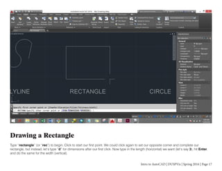
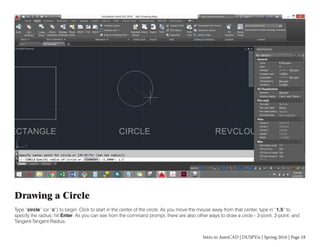
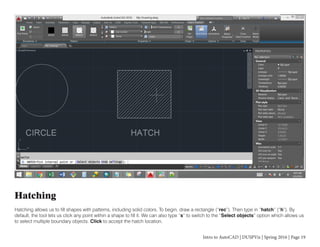
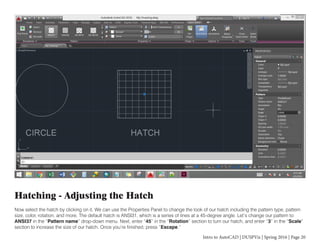
Download as PDF, PPTX


![Intro to AutoCAD | DUSPViz | Spring 2016 | Page 14
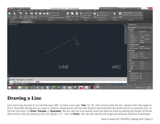
Drawing an Arc
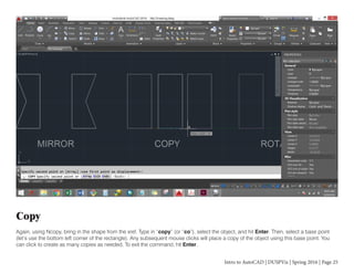
Pan over to the ARC section. To draw an arc, type “arc” (or “a”). Click once for the start point, click again for the second point, and click
one last time to end the arc. As is the case with most AutoCAD commands, the command prompt will offer different options as we draw.
After our first click, the prompt says “Specify second point of arc or [Center End]”. By typing in “center” or “end” (or their underlined
letters), we can change how we want to define our arc as we’re drawing it.](https://image.slidesharecdn.com/autocadtutorial-160424175018/85/Intro-to-AutoCAD-14-320.jpg)

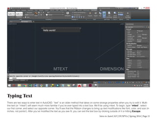


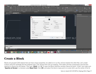
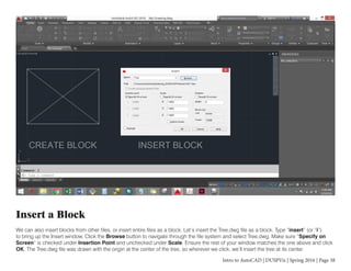
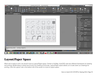


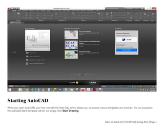
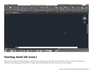
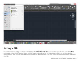
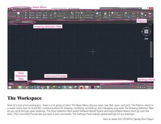
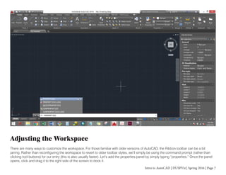
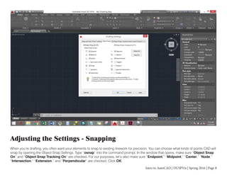
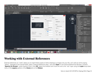
This document provides an introduction to basic functions in AutoCAD, including how to start a new drawing, save files, adjust the workspace, work with layers, insert external references, draw basic shapes like lines and circles, edit objects using grips, add hatches, and type text. It explains how to customize settings like snapping points and introduces fundamental concepts and tools in AutoCAD's interface.


![ceramic-art-and-pottery [Autosaved].pptx](https://cdn.slidesharecdn.com/ss_thumbnails/ceramic-art-and-potteryautosaved-260113113456-35c55ddb-thumbnail.jpg?width=640&height=640&fit=bounds)


