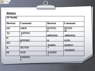
AutoCAD is a widely used CAD software developed by Autodesk, first released in 1982, for creating 2D and 3D designs across various engineering and design disciplines. The document details the functionalities of AutoCAD, including user interface elements like toolbars, command lines, and the different coordinate systems used in drawing. Additionally, it provides a comprehensive list of commands for drawing and editing, including lines, circles, dimensions, and layer management, essential for effective design work.


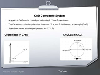
![Absolute Coordinates
All input points specify in your drawing using standard Cartesian coordinates x and y.
Using absolute coordinate, points entered by typing x,y [Enter]
Here comes your footer Page 13
Your Logo](https://image.slidesharecdn.com/autocad-131213021832-phpapp01/85/Autocad-13-320.jpg)
![Relative Coordinates
After first points entered, your next points can be entered by specifying the next
coordinate compare/relative from the first points. The relative coordinate started with
symbol "@" tell AutoCAD it was a relative coordinates. Using relative coordinate, points
entered by typing @x,y [Enter]
Here comes your footer Page 14
Your Logo](https://image.slidesharecdn.com/autocad-131213021832-phpapp01/85/Autocad-14-320.jpg)
![Polar Coordinates
Polar coordinates used when you need to draw the next points at specify angle. Polar
coordinates system in AutoCAD specifies distance length at which angle. Using polar
coordinate, points entered by typing @distance<angle [Enter]
Here comes your footer Page 15
Your Logo](https://image.slidesharecdn.com/autocad-131213021832-phpapp01/85/Autocad-15-320.jpg)
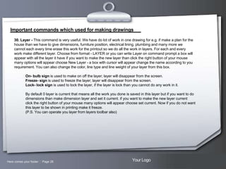
![Important commands which used for making drawings
31. There are some more commands which are not so important but you must know about them:
a) Distance - this command is used to measure the distance between the two points. Just write Di at
command prompt
Specify first point- click on the first point of line
Specify second point- click on the second point of line It will
display all the information at command prompt.
b) Revision cloud - This command is used to make the cloud like structure in which you can write your
remarks or can highlight the particular area select the command from toolbar or write revcloud at
command prompt.
Revcloud
Minimum arc length: 0.5000 Maximum arc lengths: 0.5000
Specify start point or [Arc length/Object/Style]: click to draw the revision cloud, when the start and end
lines meet, the following message is displayed on the command line. (Revision cloud finished.)
Here comes your footer Page 29
Your Logo](https://image.slidesharecdn.com/autocad-131213021832-phpapp01/85/Autocad-29-320.jpg)
![Important commands which used for making drawings
c) Spline - this command is used to measure draw the curve lines select the command from toolbar or write
spline at command prompt.
Spline
Specify first point- click on the first point of line
Specify second point- click on the second point of line It will
display all the information at command prompt.
Specify first point or [Object]: Specify a point
Specify next point: Specify a point Enter points until you have defined the spline curve. After you enter two
points, AutoCAD displays the following prompt:
Specify next point or [Close/Fit Tolerance] : Specify a point, line will complete
d) Point - This command is used to make mark the point select the command from toolbar or write Po at
command prompt.
Po
Specify a point: click where you want to locate the point, from point style menu you can select the type of point
you required, for this click on format than on point style a box will appear with all the points just click the
required one.
Here comes your footer Page 30
Your Logo](https://image.slidesharecdn.com/autocad-131213021832-phpapp01/85/Autocad-30-320.jpg)
![Important commands which used for making drawings
c) Spline - this command is used to measure draw the curve lines select the command from toolbar or write
spline at command prompt.
Spline
Specify first point- click on the first point of line
Specify second point- click on the second point of line It will
display all the information at command prompt.
Specify first point or [Object]: Specify a point
Specify next point: Specify a point Enter points until you have defined the spline curve. After you enter two
points, AutoCAD displays the following prompt:
Specify next point or [Close/Fit Tolerance] : Specify a point, line will complete
d) Point - This command is used to make mark the point select the command from toolbar or write Po at
command prompt.
Po
Specify a point: click where you want to locate the point, from point style menu you can select the type of point
you required, for this click on format than on point style a box will appear with all the points just click the
required one.
%%c
for diameter sign
%%d
for degree sign
edit command is used to edit our dimension
Here comes your footer Page 31
Your Logo](https://image.slidesharecdn.com/autocad-131213021832-phpapp01/85/Autocad-31-320.jpg)
![Important commands which used for making drawings
e) Ellipse - This command is used to draw the ellipse choose command from toolbar or write El at command
prompt.
EL
Specify axis endpoint of ellipse or [Arc/Center/Isocircle]: Specify a point or enter the value (@distance
Specify other endpoint of axis: Specify a point or enter the value (@distance
Specify distance to other axis or [Rotation]: Specify a distance by entering a value or locating a point
Specify rotation around major axis: Specify a point (3), or enter an angle value between 0 and 89.4
(P.S. you can also draw isocircle when click right button your mouse at Snap button setting box will open now
select the isometric option and you will be able to draw isocircle)
f) Divide - This command is used to divide the line in equal parts write Div at command prompt.
Div
Select object to divide: select he object you want to divide
Enter number of segments: Enter a value; object will divide if you not able to see than change the style of
point.
Here comes your footer Page 32
Your Logo](https://image.slidesharecdn.com/autocad-131213021832-phpapp01/85/Autocad-32-320.jpg)