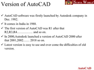
2. AutoCAD
2
Day 1 Getting started with AutoCAD: Introduction Installation Understanding the Auto CAD
Interface Screen layout Starting command from menus & icons. Understanding
Coordinate system Reading drawings
Day 2 Basic Drawing & Editing Commands: Drawing Lines Erasing Objects Drawing Lines
with Polar Tracking Drawing Rectangles Drawing Circles Viewing Your Drawing
Undoing and Redoing Actions 2. Making Your Drawings More Precise Drawing Precision in
AutoCAD Using Object Snap o Object Snap Overrides o Polar Tracking Settings o Object
Snap Tracking Drawing with SNAP and GRID
Day 3 Making Changes in Your Drawing: Selecting Objects for Editing Moving Objects
Copying Objects o Rotating Objects Scaling Objects Mirroring Objects Editing Objects
with Grips
Day 4 . Drawing Organization and Information Organizing Your Drawing with Layers Creating
New Drawings With Templates What are Layers? Layer State Changing an Object's
Layer Advanced Object Types: Drawing Arcs Drawing Polylines Editing Polylines
Drawing Polygons Drawing Ellipses
Day 5 Advanced Editing Commands Trimming and Extending Stretching Objects o Creating
Fillets and Chamfers Offsetting Objects o Creating Arrays of Objects
Auto Cad Training
Schedule
3. AutoCAD
3
Day 6 Text : Working with Annotations Adding Text in a Drawing Modifying Multiline Text
Formatting Multiline Text Hatching , Adding Dimensions Dimensioning Concepts
Adding Linear Dimensions Adding Radial and Angular Dimensions Editing
Dimensions Adding Notes to Your Drawing
Day 7 Practice and Problem session
DWF Printing and Publishing DWF Plotting and Viewing Publishing Drawing Sets
Day 8 Test Session DWF Printing and Publishing o DWF Plotting and Viewing o Publishing
Drawing Sets
Day 9 Modelling 3D Foundations: Why use 3D? Introduction to the 3D Modeling
Workspace Basic 3D Viewing Tools 3D Navigation Tools Introduction to the User
Coordinate System. Simple Solids : Working with Solid Primitives Solid Primitive
Types Working with Composite Solids Creating Solids & Surfaces from 2D Objects
Day 10 Creating Solids & Surfaces from 2D Objects: Complex 3D Geometry Extruded
Solids and Surfaces Swept Solids and Surfaces Revolved Solids and Surfaces
Lofted Solids and Surfaces
4. AutoCAD
What is AutoCAD?
• AutoCAD is a CAD (Computer Aided Design
or Computer Aided Drafting) software
application for 2D and 3D design and drafting.
5. AutoCAD
Introduction
The Word AutoCAD is made up of two words “Auto(logo
of company)”and CAD “(computer aided design)”.
It is developed by Autodesk company.
Autodesk is an U.S.A based company.
It is widely used in industry for 2D drawing and 3D modeling.
In another way we can say that AutoCAD is a designing course , which is
performed by the help of computer.
6. AutoCAD
Version of AutoCAD
AutoCAD software was firstly launched by Autodesk company in
Dec. 1982.
It comes in India in 1988.
The first version of AutoCAD was R1 after that
R2,R3,R4…………… and so on.
In 2000,Autodesk launched a version of AutoCAD 2000 after
that 2001,2002…… 2018 so on.
Latest version is easy to use and over come the difficulties of old
version.
15. AutoCAD
HOW AutoCAD WORKS
There is a co-ordinate system used in AutoCAD.
Every drawing shows its co-ordinate.
In above next slide the line shows its co-ordinate that is ( 9,6 ) and
(-10,-4).
There is so many commands like copy, move ,rotate ,mirror in 2D,
path array , rectangular array, polar array & more.
Different types of drawing can be made in the same time by using a
command that is LAYER.
Using line , arc , circle , rectangle , ellipse & polygon , so many
drawing of different type can be made.
16. AutoCAD
CO-Ordinate System
Every thing that we draw in AutoCAD is exact.
All object drawn on screen is based on simple X-Y co-ordinate
system.
In AutoCAD it is known as world co-ordinate system (WCS).
We are drawing a line, so we have two points A(-10,-4) and B(9,6).
As shown in figure.
17. AutoCAD
The UCS and WCS
The AutoCAD world is 3 dimensional. However, if we want to
draw a 2d object, such as a plan or a section, we will use only 2
dimensions (x and y).
WCS (world coordinate system) is the imaginary plane that is
parallel to the ground. It is the default coordinate system.
Modifications made to the World Coordinate System (WCS) result
in a User Coordinate System (UCS). It is the plane that you work
on. It enables the user to draw 3 dimensional objects.
To create a new UCS, type ucs on the command window, then say
New and specify 3 points on your new UCS plane.
18. AutoCAD
DRAW TOOLBAR AND MODIFY
TOOLBAR :
•Following image shows two very basic tool bars, these will be heavily
used as you progress towards the end of your drawing. You can access
these tool bars under Home tab.
As we move cursor over any tool in the tool bar a tooltip appears
stating the name of that tool. And if we further wait for about three
seconds, it turns into a brief description about that particular tool. As
shown by the following image.
For more details we can press F1 key. Now I am going to draw a
simple object. My purpose is to introduce you with the Line, Circle,
Offset, Erase, Move, Fillet and Chamfer commands. But first let us
decide about unit system, we are going to use.
19. AutoCAD
Dimension toolbar :
• AutoCAD provides a whole range of dimensioning tools which can be used to
quickly dimension any drawing without the need for measurement.
Dimensioning in AutoCAD is automatic; lines, arrows and text are all taken care
of by the dimension commands. AutoCAD dimensions are special blocks which
can easily be edited or erased as necessary.
• AutoCAD provides lots of control over the way dimensions look. Using a system
similar to text styles, dimension styles allow you to design dimensions so that
they look just the way you want them to.
We can use the following dimensional commands like
The Linear Dimension, The Continue Dimension Command, The Baseline
Dimension Command, The Aligned Dimension Command, Changing the Text, The
Radial Dimension Commands, Angular Dimensions, Annotation with Leaders,
Editing Dimensions, The Dimension Edit Command etc.
20. AutoCAD
HOW TO SET DRAWING UNITS:
To set the drawing units, go to the drop down window at the top let side of the
AutoCAD 2013 screen labeled as Format or just press Alt + o key to do so. And
from this menu select units. A pop up window will appear that will set our
drawing units as shown below.
22. AutoCAD
HATCHING IN AUTOCAD :
Hatching is used to add shaded patterns to objects and shapes within an Autocad
drawing. Hatch patterns can be used to indicate a material to be used, such as a
concrete hatch.
You will pick:
Pattern
Scale
Angle
points