This document discusses basic interrupt processing in microprocessors. It begins by explaining what interrupts are and how they allow a microprocessor to execute other tasks while waiting for external devices like keyboards. It then describes interrupt vectors, different interrupt types, and interrupt-related instructions like INT, INTO, and IRET. The document also covers interrupt processing in protected mode, including interrupt descriptors and the interrupt descriptor table. Finally, it discusses the interrupt flag bit and trap flag bit and how they are cleared during interrupt handling.
This method of checking the signal in the system for processing is called Polling Method. In this method, the problem is that the processor has to waste number of clock cycles just for checking the signal in the system, by this processor will become busy unnecessarily. If any signal came for the process, processor will take some time to process the signal due to the polling process in action. So system performance also will be degraded and response time of the system will also decrease.
This method of checking the signal in the system for processing is called Polling Method. In this method, the problem is that the processor has to waste number of clock cycles just for checking the signal in the system, by this processor will become busy unnecessarily. If any signal came for the process, processor will take some time to process the signal due to the polling process in action. So system performance also will be degraded and response time of the system will also decrease.
what is interrupts and its kinds
what is difference between interrupts and Exceptions
with diagrams and intro
compete knowledge of every thing
computer architecture lecture notes
In this chapter, the coverage of basic I/O and programmable peripheral interfaces is expanded by examining a technique called interrupt-processed I/O.
An interrupt is a hardware-initiated procedure that interrupts whatever program is currently executing.
This chapter provides examples and a detailed explanation of the interrupt structure of the entire Intel family of microprocessors.
Interrupt is a process that holds the microprocessor for a while and decide what will be next job that will done by the microprocesssor. Interrupt types ,SIM ,RIM ,DMA ,Maskable interrupt ,Non-Maskable interrupt,Trap,RST and many more has been discussed on this powerpoint . You will be able to know each of the interrupt and their functions from the slides ,some diagram that will help you to develop your knowledge about interrupt . Hardware interrupts are used by devices to communicate that they require attention from the operating system.Hardware interrupts are used by devices to communicate that they require attention from the operating system.Internally, hardware interrupts are implemented using electronic alerting signals that are sent to the processor from an external device, which is either a part of the computer itself, such as a disk controller, or an external peripheral. For example, pressing a key on the keyboard or moving the mouse triggers hardware interrupts that cause the processor to read the keystroke or mouse position.software interrupt is caused either by an exceptional condition in the processor itself, or a special instruction in the instruction set which causes an interrupt when it is executed. The former is often called a trap or exception and is used for errors or events occurring during program execution that are exceptional enough that they cannot be handled within the program itself. For example, a divide-by-zero exception will be thrown if the processor's arithmetic logic unit is commanded to divide a number by zero as this instruction is an error and impossible. The operating system will catch this exception, and can choose to abort the instruction. Software interrupt instructions can function similarly to subroutine calls and are used for a variety of purposes, such as to request services from device drivers, like interrupts sent to and from a disk controller to request reading or writing of data to and from the disk.
I hope You all like it. I hope It is very beneficial for you all. I really thought that you all get enough knowledge from this presentation. This presentation is about materials and their classifications. After you read this presentation you knowledge is not as before.
Terminal Services is a configurable service included in the Microsoft Windows 2003 Server operating system that gives it the capability to run Windows-based applications centrally from a server.
Watch this webinar to learn about the benefits of Thin Clients and Terminal Services including:
Centralised Deployment of Software,
High Scalability,
Simplified Installation Costs,
Remote Access,
and much more!
Webinar Content
Brief overview of Microsoft Terminal Services in the Manufacturing Environment
Wonderware's Answer to Thin Clients
Fault Tolerance
Availability Requirements
Licensing Structure
Summary
LF Energy Webinar: Electrical Grid Modelling and Simulation Through PowSyBl -...DanBrown980551
Do you want to learn how to model and simulate an electrical network from scratch in under an hour?
Then welcome to this PowSyBl workshop, hosted by Rte, the French Transmission System Operator (TSO)!
During the webinar, you will discover the PowSyBl ecosystem as well as handle and study an electrical network through an interactive Python notebook.
PowSyBl is an open source project hosted by LF Energy, which offers a comprehensive set of features for electrical grid modelling and simulation. Among other advanced features, PowSyBl provides:
- A fully editable and extendable library for grid component modelling;
- Visualization tools to display your network;
- Grid simulation tools, such as power flows, security analyses (with or without remedial actions) and sensitivity analyses;
The framework is mostly written in Java, with a Python binding so that Python developers can access PowSyBl functionalities as well.
What you will learn during the webinar:
- For beginners: discover PowSyBl's functionalities through a quick general presentation and the notebook, without needing any expert coding skills;
- For advanced developers: master the skills to efficiently apply PowSyBl functionalities to your real-world scenarios.
Accelerate your Kubernetes clusters with Varnish CachingThijs Feryn
A presentation about the usage and availability of Varnish on Kubernetes. This talk explores the capabilities of Varnish caching and shows how to use the Varnish Helm chart to deploy it to Kubernetes.
This presentation was delivered at K8SUG Singapore. See https://feryn.eu/presentations/accelerate-your-kubernetes-clusters-with-varnish-caching-k8sug-singapore-28-2024 for more details.
JMeter webinar - integration with InfluxDB and GrafanaRTTS
Watch this recorded webinar about real-time monitoring of application performance. See how to integrate Apache JMeter, the open-source leader in performance testing, with InfluxDB, the open-source time-series database, and Grafana, the open-source analytics and visualization application.
In this webinar, we will review the benefits of leveraging InfluxDB and Grafana when executing load tests and demonstrate how these tools are used to visualize performance metrics.
Length: 30 minutes
Session Overview
-------------------------------------------
During this webinar, we will cover the following topics while demonstrating the integrations of JMeter, InfluxDB and Grafana:
- What out-of-the-box solutions are available for real-time monitoring JMeter tests?
- What are the benefits of integrating InfluxDB and Grafana into the load testing stack?
- Which features are provided by Grafana?
- Demonstration of InfluxDB and Grafana using a practice web application
To view the webinar recording, go to:
https://www.rttsweb.com/jmeter-integration-webinar
DevOps and Testing slides at DASA ConnectKari Kakkonen
My and Rik Marselis slides at 30.5.2024 DASA Connect conference. We discuss about what is testing, then what is agile testing and finally what is Testing in DevOps. Finally we had lovely workshop with the participants trying to find out different ways to think about quality and testing in different parts of the DevOps infinity loop.
UiPath Test Automation using UiPath Test Suite series, part 3DianaGray10
Welcome to UiPath Test Automation using UiPath Test Suite series part 3. In this session, we will cover desktop automation along with UI automation.
Topics covered:
UI automation Introduction,
UI automation Sample
Desktop automation flow
Pradeep Chinnala, Senior Consultant Automation Developer @WonderBotz and UiPath MVP
Deepak Rai, Automation Practice Lead, Boundaryless Group and UiPath MVP
State of ICS and IoT Cyber Threat Landscape Report 2024 previewPrayukth K V
The IoT and OT threat landscape report has been prepared by the Threat Research Team at Sectrio using data from Sectrio, cyber threat intelligence farming facilities spread across over 85 cities around the world. In addition, Sectrio also runs AI-based advanced threat and payload engagement facilities that serve as sinks to attract and engage sophisticated threat actors, and newer malware including new variants and latent threats that are at an earlier stage of development.
The latest edition of the OT/ICS and IoT security Threat Landscape Report 2024 also covers:
State of global ICS asset and network exposure
Sectoral targets and attacks as well as the cost of ransom
Global APT activity, AI usage, actor and tactic profiles, and implications
Rise in volumes of AI-powered cyberattacks
Major cyber events in 2024
Malware and malicious payload trends
Cyberattack types and targets
Vulnerability exploit attempts on CVEs
Attacks on counties – USA
Expansion of bot farms – how, where, and why
In-depth analysis of the cyber threat landscape across North America, South America, Europe, APAC, and the Middle East
Why are attacks on smart factories rising?
Cyber risk predictions
Axis of attacks – Europe
Systemic attacks in the Middle East
Download the full report from here:
https://sectrio.com/resources/ot-threat-landscape-reports/sectrio-releases-ot-ics-and-iot-security-threat-landscape-report-2024/
Dev Dives: Train smarter, not harder – active learning and UiPath LLMs for do...UiPathCommunity
💥 Speed, accuracy, and scaling – discover the superpowers of GenAI in action with UiPath Document Understanding and Communications Mining™:
See how to accelerate model training and optimize model performance with active learning
Learn about the latest enhancements to out-of-the-box document processing – with little to no training required
Get an exclusive demo of the new family of UiPath LLMs – GenAI models specialized for processing different types of documents and messages
This is a hands-on session specifically designed for automation developers and AI enthusiasts seeking to enhance their knowledge in leveraging the latest intelligent document processing capabilities offered by UiPath.
Speakers:
👨🏫 Andras Palfi, Senior Product Manager, UiPath
👩🏫 Lenka Dulovicova, Product Program Manager, UiPath
Key Trends Shaping the Future of Infrastructure.pdfCheryl Hung
Keynote at DIGIT West Expo, Glasgow on 29 May 2024.
Cheryl Hung, ochery.com
Sr Director, Infrastructure Ecosystem, Arm.
The key trends across hardware, cloud and open-source; exploring how these areas are likely to mature and develop over the short and long-term, and then considering how organisations can position themselves to adapt and thrive.
Software Delivery At the Speed of AI: Inflectra Invests In AI-Powered QualityInflectra
In this insightful webinar, Inflectra explores how artificial intelligence (AI) is transforming software development and testing. Discover how AI-powered tools are revolutionizing every stage of the software development lifecycle (SDLC), from design and prototyping to testing, deployment, and monitoring.
Learn about:
• The Future of Testing: How AI is shifting testing towards verification, analysis, and higher-level skills, while reducing repetitive tasks.
• Test Automation: How AI-powered test case generation, optimization, and self-healing tests are making testing more efficient and effective.
• Visual Testing: Explore the emerging capabilities of AI in visual testing and how it's set to revolutionize UI verification.
• Inflectra's AI Solutions: See demonstrations of Inflectra's cutting-edge AI tools like the ChatGPT plugin and Azure Open AI platform, designed to streamline your testing process.
Whether you're a developer, tester, or QA professional, this webinar will give you valuable insights into how AI is shaping the future of software delivery.
Neuro-symbolic is not enough, we need neuro-*semantic*Frank van Harmelen
Neuro-symbolic (NeSy) AI is on the rise. However, simply machine learning on just any symbolic structure is not sufficient to really harvest the gains of NeSy. These will only be gained when the symbolic structures have an actual semantics. I give an operational definition of semantics as “predictable inference”.
All of this illustrated with link prediction over knowledge graphs, but the argument is general.
Neuro-symbolic is not enough, we need neuro-*semantic*
Interrupts
1. 12-1 BASIC INTERRUPT PROCESSING 459
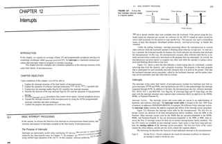
CHAPTER 12 FIGURE 12-1 A time line
that indicates interrupt usage
Keyboard interrupt Printer interrupt Keyboard interrupt
1I 1
in a typical system. 1 I 1
Interrupts 1 Main program
Printer interrupt
IBF bit to decide whether data were available from the keyboard. If the person using the key-
board typed one character per second, the software for the 82C55 waited an entire second be-
tween each keystroke for the person to type another key. This process was such a tremendous
waste of time that designers developed another process, interrupt processing, to handle this
situation.
Unlike the polling technique, interrupt processing allows the microprocessor to execute
other software while the keyboard operator is thinking about what key to type next. As soon as a
INTRODUCTION key is pressed, the keyboard encoder de-bounces the switch and puts out one pulse that interrupts
the microprocessor. In this way, the microprocessor executes other software until the key is ac-
In this chapter, we expand our coverage of basic I/O and programmable peripheral interfaces by tually pressed when it reads a key and returns to the program that was interrupted. As a result, the
examining a technique called interrupt-processed I/O. An interrupt is a hardware-initialed pro- microprocessor can print reports or complete any other task while the operator is typing a docu-
cedure that interrupts whatever program is currently executing. ment and thinking about what to type next.
This chapter provides examples and a detailed explanation of the interrupt structure of the Figure 12-1 shows a time line that indicates a typist typing data on a keyboard, a printer
entire Intel family of microprocessors. removing data from the memory, and a program executing. The program is the main program
that is interrupted for each keystroke and each character that is to print on the printer. Note that
the keyboard interrupt service procedure, called by the keyboard interrupt, and the printer inter-
rupt service procedure each take little time to execute.
CHAPTER OBJECTIVES
Upon completion of this chapter, you will be able to: Interrupts
1. Explain the interrupt structure of the Intel family of microprocessors. The interrupts of the entire Intel family of microprocessors include two hardware pins that re-
2. Explain the operation of software interrupt instructions INT, INTO, INT 3, and BOUND. quest interrupts (INTR and NMI), and one hardware pin (INTA) that acknowledges the interrupt
3. Explain how the interrupt enable flag bit (IF) modifies the interrupt structure. requested through INTR. In addition to the pins, the microprocessor also has software interrupts
4. Describe the function of the trap interrupt flag-bit (TF) and the operation of trap-generated INT, INTO, INT 3, and BOUND. Two flag bits, IF (interrupt flag) and TF (trap flag), are also
tracing. used with the interrupt structure and a special return instruction IRET (or IRETD in the 80386,
5. Develop interrupt-service procedures that control lower-speed, external peripheral devices. 80486, or Pentium-Pentium II).
6. Expand the interrupt structure of the microprocessor by using the 8259A programmable
Interrupt Vectors. The interrupt vectors and vector table are crucial to an understanding of
interrupt controller and other techniques. hardware and software interrupts. The interrupt vector table is located in the first 1024 bytes
7. Explain the purpose and operation of a real-time clock. of memory at addresses OOOOOOH-0003FFH. It contains 256 different 4-byte interrupt vectors.
An interrupt vector contains the address (segment and offset) of the interrupt service procedure.
Figure 12-2 illustrates the interrupt vector table for the microprocessor. The first five in-
terrupt vectors are identical in all Intel microprocessor family members, from the 8086 to the
Pentium. Other interrupt vectors exist for the 80286 that are upward-compatible to the 80386,
12-1 BASIC INTERRUPT PROCESSING 80486, and Pentium-Pentium II, but not downward-compatible to the 8086 or 8088. Intel re-
In this section, we discuss the function of an interrupt in a microprocessor-based system, and serves the first 32 interrupt vectors for their use in various microprocessor family members. The
structure and features of interrupts available to the Intel family of microprocessors. last 224 vectors are available as user interrupt vectors. Each vector is four bytes long and con-
tains the starting address of the interrupt service procedure. The first two bytes of the vector
contain the offset address, and the last two bytes contain the segment address.
The Purpose of Interrupts The following list describes the function of each dedicated interrupt in the microprocessor:
Interrupts are particularly useful when interfacing I/O devices tt
Type 0 Divide Error—Occurs whenever the result of a division overflows or whenever
relatively low data-transfer rates. In Chapter 11, for instance, we
an attempt is made to divide by zero.
using strobed input operation of the 82C55. In that example, software polled the 82<
458
2. 12-1 BASIC INTERRUPT PROCESSING 461
CHAPTER 12 INTERRUPTS
460 Type 2 Non-maskable Hardware Interrupt—A result of placing a logic 1 on the NMI
FIGURE 12-2 (a) The input pin to the microprocessor. This input is non-maskable, which means that it
interrupt vector table for the cannot be disabled.
microprocessor, and (b) the Type 3 One-Byte Interrupt—A special one-byte instruction (INT 3) that uses this vector
Type 32 — 255
contents of an interrupt vector. User interrupt vectors to access its interrupt-service procedure. The INT 3 instruction is often used to
store a breakpoint in a program for debugging.
080H
Type 14— 31 Type 4 Overflow—A special vector used with the INTO instruction. The INTO
Reserved instruction interrupts the program if an overflow condition exists, as reflected by
the overflow flag (OF).
Type 16
TypeS BOUND—An instruction that compares a register with boundaries stored in the
Coprocessor error memory. If the contents of the register are greater than or equal to the first word
04QH in memory and less than or equal to the second word, no interrupt occurs because
Type 15
Unassigned the contents of the register is within bounds. If the contents of the register are
03CH out-of-bounds, a type 5 interrupt ensues.
Type 14
Page fault Type 6 Invalid Opcode—Occurs whenever an undefined opcode is encountered in a
038H
Type 13 program.
General protection
034H Type? Coprocessor Not Available—Occurs when a coprocessor is not found in the
Type 12 system, as dictated by the machine status word (MSW) coprocessor control bits.
Stack segment overrun^
030H If an ESC or WAIT instruction executes and the coprocessor is not found, a type
Type 11 7 exception or interrupt occurs.
Segment not present
02CH TypeS Double Fault—Activated whenever two separate interrupts occur during the
Type 10
Invalid task state segment
same instruction.
028H Type 9 Coprocessor Segment Overrun—Occurs if the ESC instruction (coprocessor
Type 9
Coprocessor segment overrun opcode) memory operand extends beyond offset address FFFFH.
024H
Type8 Type 10 Invalid Task State Segment—Occurs if the TSS is invalid because the segment
Double fault limit field is not 002BH or higher. In most cases, this is caused because the TSS
020H
Type 7 is not initialized.
Coprocessor not available
01CH Type 11 Segment not Present—Occurs when the P bit (P = 0) in a descriptor indicates
Type 6 that the segment is not present or not valid.
Undefined opcode
018H Type 12 Stack Segment Overrun—Occurs if the stack segment is not present (P = 0) or if
Type 5
BOUND
the limit of the stack segment is exceeded.
014H Type 13 General Protection—Occurs for most protection violations in the 80286-Pentium
Type 4
Overflow (INTO) II protected mode system. (These errors occur in Windows as general
01 OH protection faults.) A list of these protection violations follows:
TypeS
1-byte breakpoint a. Descriptor table limit exceeded
OOCH Any interrupt vector^ b. Privilege rules violated
Type 2
NMI pin Segment (high) c. Invalid descriptor segment type loaded
008H d. Write to code segment that is protected
Type 1 Segment (low)
Single-step
Offset (high)
e. Read from execute-only code segment
004H f. Write to read-only data segment
TypeO Offset (low)
Divide error g. Segment limit exceeded
OOOH h. CPL = IOPL when executing CTS, HLT, LGDT, LIDT, LLDT, LMSW, or LTR
(b)
(a)
i. CPL > IOPL when executing CLI, IN, INS, LOCK, OUT, OUTS, and STI
Type 14 Page Fault—Occurs for any page fault memory or code access in the 80386,
or Trap-Occurs after 80486, and Pentium-Pentium II microprocessors.
Typel
Type 16 Coprocessor Error—Takes effect whenever a coprocessor error (ERROR = 0)
occurs for the ESCape or WAIT instructions for the 80386, 80486, and
this interrupt later in this section of the chapter.) Pentium-Pentium II microprocessors only.
3. 12-1 BASIC INTERRUPT PROCESSING
462 CHAPTER 12 INTERRUPTS 463
Type 17 Alignment Check—Indicates that word and doubleword data are addressed at an Whenever an interrupt is accepted, the microprocessor stacks the contents of the flag reg-
odd memory location (or an incorrect location, in the case of a doubleword). This ister, CS and IP; clears both IF and TF; and jumps to the procedure addressed by the interrupt
interrupt is active in the 80486 and Pentium-Pentium II microprocessors. vector. After the flags are pushed onto the stack, IF and TF are cleared. These flags are returned
to the state prior to the interrupt when the IRET instruction is encountered at the end of the in-
Type 18 Machine Check—Activates a system memory management mode interrupt in the
terrupt service procedure. Therefore, if interrupts were enabled prior to the interrupt service pro-
Pentium-Pentium II microprocessors. cedure, they are automatically re-enabled by the IRET instruction at the end of the procedure.
The return address (in CS and IP) is pushed onto the stack during the interrupt. Sometimes,
Interrupt Instructions: BOUND, INTO, I NT, INT3, and IRET the return address points to the next instruction in the program; sometimes it points to the in-
Of the five software interrupt instructions available to the microprocessor, INT and INT 3 are very struction or point in the program where the interrupt occurred. Interrupt type numbers 0, 5, 6, 7,
similar, BOUND and INTO are conditional, and IRET is a special interrupt return instruction. 8, 10, 11, 12, and 13 push a return address that points to the offending instruction, instead of to
The BOUND instruction, which has two operands, compares a register with two words of the next instruction in the program. This allows the interrupt service procedure to possibly retry
the instruction in certain error cases.
memory data. For example, if the instruction BOUND AX,DATA is executed, AX is compared
with the contents of DATA and DATA+1 and also with DATA+2 and DATA+3. If AX is less Some of the protected mode interrupts (types 8, 10, 11, 12, and 13) place an error code on
than the contents of DATA and DATA+1, a type 5 interrupt occurs. If AX is greater than the stack following the return address. The error code identifies the selector that caused the in-
terrupt. In cases where no selector is involved, the error code is a 0.
DATA+2 and DATA+3, a type 5 interrupt occurs. If AX is within the bounds of these two
memory words, no interrupt occurs. Operation of a Protected Mode Interrupt
The INTO instruction checks the overflow flag (OF). If OF = 1, the INTO instruction calls
the procedure whose address is stored in interrupt vector type number 4. If OF = 0, then the INTO In the protected mode, interrupts have exactly the same assignments as in the real mode, but the
instruction performs no operation and the next sequential instruction in the program executes. interrupt vector table is different. In place of interrupt vectors, protected mode uses a set of 256
The INT n instruction calls the interrupt service procedure that begins at the address repre- interrupt descriptors that are stored in an interrupt descriptor table (IDT). The interrupt de-
sented in vector number n. For example, an INT 80H or INT 128 calls the interrupt service pro- scriptor table is 256 x 8 (2K) bytes long, with each descriptor containing eight bytes. The inter-
cedure whose address is stored in vector type number 80H (000200H-00203H). To determine rupt descriptor table is located at any memory location in the system by the interrupt descriptor
the vector address, just multiply the vector type number (n) by 4, which gives the beginning ad- table address register (IDTR).
dress of the 4-byte long interrupt vector. For example, an INT 5 = 4 x 5 or 20 (14H). The vector Each entry in the IDT contains the address of the interrupt service procedure in the form of a
for INT 5 begins at address 000014H and continues to 000017H. Each INT instruction is stored segment selector and a 32-bit offset address. It also contains the P bit (present) and DPL bits to de-
in two bytes of memory: the first byte contains the opcode, and the second byte contains the in- scribe the privilege level of the interrupt. Figure 12-3 shows the contents of the interrupt descriptor.
terrupt type number. The only exception to this is the INT 3 instruction, a 1-byte instruction. The Real mode interrupt vectors can be converted into protected mode interrupts by copying
INT 3 instruction is often used as a breakpoint-interrupt because it is easy to insert a 1-byte in- the interrupt procedure addresses from the interrupt vector table and converting them to 32-bit
struction into a program. Breakpoints are often used to debug faulty software. offset addresses that are stored in the interrupt descriptors. A single selector and segment de-
The IRET instruction is a special return instruction used to return for both software and scriptor can be placed in the global descriptor table that identifies the first 1M byte of memory as
hardware interrupts. The IRET instruction is much like a far RET, because it retrieves the return the interrupt segment.
address from the stack. It is unlike the near return because it also retrieves a copy of the flag reg- Other than the IDT and interrupt descriptors, the protected mode interrupt functions like
ister from the stack. An IRET instruction removes six bytes from the stack: two for the IP, two the real mode interrupt. We return from both interrupts by using the IRET or IRETD instruction.
for the CS, and two for the flags. The only difference is that in protected mode the microprocessor accesses the IDT instead of the
In the 80386-Pentium II, there is also an IRETD instruction because these microprocessors interrupt vector table.
can push the EFEAG register (32 bits) on the stack, as well as the 32-bit EIP in the protected mode.
If operated in the real mode, we use the IRET instruction with the 80386-Pentium II micro-
Interrupt Flag Bits
processors. The interrupt flag (IF) and the trap flag (TF) are both cleared after the contents of the flag reg-
ister are stacked during an interrupt. Figure 12-4 illustrates the contents of the flag register and
The Operation of a Real Mode Interrupt
When the microprocessor completes executing the current instruction, it determines whether an FIGURE 12-3 The pro-
interrupt is active by checking (1) instruction executions, (2) single-step, (3) NMI, (4) co- tected mode interrupt
processor segment overrun, (5) INTR, and (6) INT instruction in the order presented. If one oi| descriptor. Offset (A31-A16)
more of these interrupt conditions are present, the following sequence of events occurs:
DPL 0 1 1 1 0 0 0 H
1. The contents of the flag register are pushed onto the stack.
2. Both the interrupt (IF) and trap (TF) flags are cleared. This disables the INTR pin and
trap or single-step feature. Segment selector
3. The contents of the code segment register (CS) are pushed onto the stack.
4. The contents of the instruction pointer (IP) are pushed onto the stack.
5. The interrupt vector contents are fetched, and then placed into both IP and CS so that Offset (A15-AO)
next instruction executes at the interrupt service procedure addressed by the vector.
4. 464 CHAPTER 12 INTERRUPTS 12-1 BASIC INTERRUPT PROCESSING
465
FIGURE 12-4 The flag
FLAGS 0 DM T S Z instruction executes following INT 40H-the TRACE procedure displays the contents of all the
register. (Courtesy of Intel
15 11 10 9 8 7 6 5 4 3 2 1 0 16-bit microprocessor registers on the CRT screen. This provides a register trace of all the in-
Corporation.)
structions between the INT 40H (TRON) and INT 41H (TROFF).
EXAMPLE 12-3
the location of IF and TF. When the IF bit is set, it allows the INTR pin to cause an interrupt;
when the IF bit is cleared, it prevents the INTR pin from causing an interrupt. When TF = 1, it .MODEL TINY
0000 .CODE
causes a trap interrupt (type number 1) to occur after each instruction executes. This is why we 0000 41 58 20 3D 20 42 RNAME DB 'AX = ','BX = ','CX = ','DX =
often call trap a single-step. When TF = 0, normal program execution occurs. This flag bit allows 58 20 3D 20 43 58
debugging, as explained in Chapters 17-19, which detail the 80386-Pentium II. 20 3D 20 44 58 20
3D 20
The interrupt flag is set and cleared by the STI and CLI instructions, respectively. There 0014 53 50 20 3D 20 42 DB 'SP = ','BP = ','SI = ','DI =
are no special instructions that set or clear the trap flag. Example 12-1 shows an interrupt service 50 20 3D 20 53 49
procedure that turns tracing on by setting the trap flag bit on the stack from inside the procedure. 0 3D 20 44 49 20
3D 20
Example 12-2 shows an interrupt service procedure that turns tracing off by clearing the trap 49 50 20 3D 20 46 DB 'IP =
flag on the stack from within the procedure. 4C 20 3D 20 43 53
20 3D 20 44 53 20
EXAM RLE 12-1 3D 20
003C 45 53 20 3D 20 53 DB 'ES =
;A procedure that sets TF to enable trap. 53 20 3D 20
0000 TRON PROC NEAR DISP MACRO PAR1
PUSH AX
0000 50 PUSH AX save registers PUSH DX
0001 55 PUSH BP MOV DL,PAR1
0002 8B EC MOV BP,SP get SP MOV AH, 6
0004 8B 46 08 MOV AX,[BP+8] get flags from stack INT 21H
0007 80 CC 01 OR AH,1 set TF POP DX
OOOA 89 46 08 MOV [BP+8],AX save flags POP AX
OOOD 5D POP BP restore registers ENDM
OOOE 58 POP AX
OOOF CF I RET CRLF MACRO
DISP 13
0010 TRON ENDP DISP 10
ENDM
EXAMPLE 12-2 0046 TRACE PROC FAR USES AX BP BX
;A procedure that clears TF to disable trap.
0049 BB 0000 R MOV BX, OFFSET RNAME ;address names
0000 TROFF PROC NEAR CRLF
0060 E8 004D CALL DREG
0063 58 ;display AX
0000 50 PUSH AX save registers POP AX ;get BX
0001 55 PUSH BP 0064 50 PUSH AX
0002 8B EC MOV BP,SP get SP 0065 E8 0048 CALL DREG
0068 8B Cl ;display BX
0004 8B 46 08 MOV AX,[BP+8] get TF MOV AX,CX
0007 80 E4 FE AND AH,OFEH clear TF 006A E8 0043 CALL DREG
006D SB C2 ;display CX
OOOA 89 46 08 MOV [BP+8],AX save flags MOV AX,DX
OOOD 5D POP BP restore registers 006F E8 003E CALL DREG ;display DX
OOOE 58 POP AX 0072 8B C4 MOV AX,SP
OOOF CF I RET 0074 83 CO OC ADD AX, 12
0077 E8 0036 CALL DREG
007A 8B C5 /display SP
0010 TROFF ENDP MOV AX,BP
007C E8 0031 CALL DREG
007F SB C6 ;display BP
MOV AX, SI
In both examples, the flag register is retrieved from the stack by using the BP 0081 E8 002C CALL DREG
0084 /display SI
which, by default, addresses the stack segment. After the flags are retrieved, the TF bit is SB C7 MOV AX,DI
0086 E8 0027 CALL DREG
set (TRON) or clears (TROFF) before returning from the interrupt service procedure. The 0089 8B EC /display DI
MOV BP,SP
instruction restores the flag register with the new state of the trap flag. -«*«** 008B 8B 46 06 MOV AX, [BP+ 6]
008E E8 001F CALL DREG
Trace Procedure. Assuming that TRON is accessed by an INT 40H instruction and 0091 SB 46 OA ;display IP
MOV AX, [BP+ 10]
accessed by an INT 41H instruction, Example 12-3 traces through a program immediately 0094 E8 0019 CALL DREG
0097 SB 46 08 /display Flags
lowing the INT 40H instruction. The interrupt service procedure illustrated in Example MOV AX, [BP+ 8]
009A E8 0013 CALL DREG
responds to interrupt type number 1 or a trap interrupt. Each time that a trap occurs—after 009D 8C D8 /display CX
MOV AX,DS
5. 12-2 HARDWARE INTERRUPTS 467
466 CHAPTER 12 INTERRUPTS
CALL DREG ;display DS 010B B4 35 MOV AH,35H ; get old interrupt vector
009F E8 OOOE
MOV AX,ES 010D BO 40 MOV AL,40H
OOA2 8C CO
CALL DREG ;display ES 010F CD 21 INT 21H
OOA4 E8 0009
MOV AX,SS 0111 89 IE 0102 R MOV WORD PTR OLD,BX
OOA7 8C DO
E8 0004 CALL DREG /display SS 0115 8C 06 0104 R MOV WORD PTR OLD+2,ES
OOA9
IRET
; install new interrupt vector 40H
OOBO TRACE ENDP
0119 BA 0106 R MOV DX, OFFSET NEW40
OOBO DREG PROC NEAR USES CX one B4 25 MOV AH,25H
GOBI MOV CX,5 ; load count 011E BO 40 MOV AL,40H
OOB4 0120 CD 21 INT 21H
DISP CS: [BX] ; display character
OOBF 43 INC BX ; address next ; leave NEW40 in memory
OOCO E2 F2 LOOP DREG1 ; repeat 5 times
OOC2 B9 0004 MOV CX , 4 ; load count 0122 BA 0107 R MOV DX, OFFSET START
OOC5 0125 Dl EA SHR DX,1
OOC5 D3 C8 ROL AX,1 /position digit 0127 Dl EA SHR DX,1
OOC7 D3 C8 ROL AX,1 0129 Dl EA SHR DX, 1
OOC9 D3 C8 ROL AX,1 012B Dl EA SHR DX,1
OOCB D3 C8 ROL AX,1 012D 42 INC DX
OOCD 50 PUSH AX 012E B8 3100 MOV AX,3100H
OOCE 24 OF AND AL,OFH ; convert to ASCII 0131 CD 21 INT 21H
. IF AL > 9 END
OOD4 04 07 ADD AL,7
. ENDIF
OOD6 04 30 ADD AL , 3 OH
DISP AL
OOE2 58 POP AX
OOE3 E2 EO LOOP DREG2 ; repeat 4 times 12-2 HARDWARE INTERRUPTS
DISP ' '
RET
The microprocessor has two hardware interrupt inputs: non-maskable interrupt (NMI) and inter-
DREG ENDP rupt request (INTR). Whenever the NMI input is activated, a type 2 interrupt occurs because
END NMI is internally decoded. The INTR input must be externally decoded to select a vector. Any
interrupt vector can be chosen for the INTR pin, but we usually use an interrupt type number be-
Storing an Interrupt Vector in the Vector Table tween 20H and FFH. Intel has reserved interrupts OOH through IFH for internal and future ex-
In order to install an interrupt vector—sometimes called a hook—the assembler must address pansion. The INTA signal is also an interrupt pin on the microprocessor, but it is an output that
absolute memory. Example 12-4 shows how a new vector is added to the interrupt vector table is used in response to the INTR input to apply a vector type number to the data bus connections
by using the assembler and a DOS function call. Here, INT 21H function call number 25H ini- D7-DO. Figure 12-5 shows the three user interrupt connections on the microprocessor.
tializes the interrupt vector. Notice that the first thing done in this procedure is to save the old in- The non-maskable interrupt (NMI) is an edge-triggered input that requests an interrupt
terrupt vector number by using DOS INT 21H function call number 35H to read the current on the positive edge (0-to-l transition). After a positive edge, the NMI pin must remain a logic 1
vector. See Appendix A for more detail on DOS INT 21H function calls. until it is recognized by the microprocessor. Note that before the positive edge is recognized, the
NMI pin must be a logic 0 for at least two clocking periods.
EXAMPLE 12-4 The NMI input is often used for parity errors and other major system faults, such as power
failures. Power failures are easily detected by monitoring the AC power line and causing an NMI
.MODEL TINY
.CODE
;A program that installs NEW40 at INT 4OH.
FIGURE 12-5 The interrupt
.STARTUP pins on al! versions of the
0100 05 JMP START Intel microprocessor.
OLD DD NMI
Interrupt inp
;new interrupt procedure INTR
0106 NEW4 0 PROC FAR INTA Interrupt out
0106 CF IRET
0107 NEW40 ENDP
0107
0107 8C C8 MOV AX,CS ;get data segment
0109 8E D8 MOV DS,AX
6. 468 CHAPTER 12 INTERRUPTS 12-2 HARDWARE INTERRUPTS
469
1.1 When DC power fails, the battery provides a reduced voltage to the Vcc connection on the
CEXT
memory device. Most memory devices will retain data with Vcc voltages as low as 1.5 V, so the
CJ
battery voltage does not need to be +5.0 V. The WR pin is pulled to Vcc during a power outage,
vcc o-v^x —1_13_
R
I REXT/CEXT
so no data will be written to the memory.
vcc -SL RIN
INTR and INTO
Al
<1K U1A ^ A2 The interrupt request input (INTR) is level-sensitive, which means that it must be held at a logic
47K 4
Bl
B2
Q
_
^ 1 level until it is recognized. The INTR pin is set by an external event and cleared inside the in-
~$C CLR Q NMI
74ALS14 terrupt service procedure. This input is automatically disabled once it is accepted by the micro-
VAC
1 -
J
=-
6
> IK
vcc
74LS122 processor and re-enabled by the IRET instruction at the end of the interrupt service procedure.
The 80386-Pentium II use the IRETD instruction in the protected mode of operation.
The microprocessor responds to the INTR input by pulsing the INTA output in anticipa-
tion of receiving an interrupt vector type number on data bus connection D7-DO. Figure 12-8
FIGURE 12-6 A power failure detection circuit. shows the timing diagram for the INTR and INTA pins of the microprocessor. There are two
INTA pulses generated by the system that are used to insert the vector type number on the data
bus.
interrupt whenever AC power drops out. In response to this type of interrupt, the microprocessor Figure 12-9 illustrates a simple circuit that applies interrupt vector type number FFH to
stores all of the internal register in a battery backed-up-memory or an EEPROM. Figure 12-6 the data bus in response to an INTR. Notice that the INTA pin is not connected in this circuit.
shows a power failure detection circuit that provides a logic 1 to the NMI input whenever AC Because resistors are used to pull the data bus connections (DO-D7) high, the microprocessor au-
power is interrupted. tomatically sees vector type number FFH in response to the INTR input. This is possibly the
In this circuit, an optical isolator provides isolation from the AC power line. The output of least expensive way to implement the INTR pin on the microprocessor.
the isolator is shaped by a Schmitt-trigger inverter that provides a 60 Hz pulse to the trigger input
Using a Three-State Buffer for INTA. Figure 12-10 shows how interrupt vector type number
of the 74LS122 retriggerable monostable multivibrator. The values of R and C are chosen so that
80H is applied to the data bus (DO-D7) in response to an INTR. In response to the INTR, the
the 74LS122 has an active pulse width of 33 ms or 2 AC input periods. Because the 74LS122 is
microprocessor outputs the INTA that is used to enable a 74ALS244 three-state octal buffer.
retriggerable, as long as AC power is applied, the Q output remains triggered at a logic 1 and Q
The octal buffer applies the interrupt vector type number to the data bus in response to the
remains a logic 0. INTA pulse. The vector type number is easily changed with the DIP switches that are shown in
If the AC power fails, the 74LS122 no longer receives trigger pulses from the 74ALS14, this illustration.
which means that Q returns to a logic 0 and Q returns to a logic 1, interrupting the micro-
processor through the NMI pin. The interrupt service procedure, not shown here, stores the con- Making the INTR Input Edge-triggered. Often, we need an edge-triggered input instead of a
tents of all internal registers and other data into a battery-backed-up memory. This system level-sensitive input. The INTR input can be converted to an edge-triggered input by using a D-
assumes that the system power supply has a large enough filter capacitor to provide energy for at type flip-flop, as illustrated in Figure 12-11. Here, the clock input becomes an edge-triggered
least 75 ms after the AC power ceases. interrupt request input, and the clear input is used to clear the request when the INTA signal is
Figure 12-7 shows a circuit that supplies power to a memory after the DC power fails. output by the microprocessor. The RESET signal initially clears the flip-flop so that no inter-
Here, diodes are used to switch supply voltages from the DC power supply to the battery. The rupt is requested when the system is first powered.
diodes used are standard silicon diodes because the power supply to this memory circuit is ele-
vated above +5.0 V to +5.7 V. The resistor is used to trickle-charge the battery, which is either
NiCAD, Lithium, or a gel cell. INTR
FIGURE 12-7 A battery- INTA
backed-up memory system + 9.0V—— vi G vo r
using a NiCad, lithium, or gel N
D J5 00 LOCK
cell. 4.7K
t 2^
10K
Vcc
WR
INTA
-0----0---
D7-DO
—
Memory
Vector number
FIGURE 12-8 The timing of the INTR input and INTA output. *Note: This portion of the data
bus is ignored and usually contains the vector number.
7. 470 CHAPTER 12 INTERRUPTS 12-2 HARDWARE INTERRUPTS
471
FIGURE 12-9 A simple vcc FIGURE 12-11 Converting
Q INTR into an edge-triggered
method for generating inter-
rupt vector type number FFH interrupt request input.
in response to INTR. i1 1 1111
6 5 A 32 109
man ™
1 2 :5 45 6 7 8
Edge-triggered
interrupt request
DO
Dl
D2
D3 Low data bus
D4
D5
D6
D7
INTA No connection RESET
74ALS04
The 82C55 Keyboard Interrupt
FIGURE 12-10 A circuit
The keyboard example presented in Chapter 11 provides a simple example of the operation of
that applies any interrupt
vector type number in re- the INTR input and an interrupt. Figure 12-12 illustrates the interconnection of the 82C55 with
sponse to TNTA. Here the DO the microprocessor and the keyboard. It also shows how a 74ALS244 octal buffer is used to pro-
Dl
circuit is applying type D2 vide the microprocessor with interrupt vector type number 40H in response to the keyboard in-
number 80H. D3 Low data bus terrupt during the INTA pulse.
D4
D5 The 82C55 is decoded at 80386SX I/O port address 0500H, 0502H, 0504H, and 0506H by
D6 a PAL16L8 (the program is not illustrated). The 82C55 is operated in mode 1 (strobed input
D7
mode), so whenever a key is typed, the INTR output (PC3) becomes a logic 1 and requests an in-
1 1 1 1
864 2 9 7 5 3 terrupt through the INTR pin on the microprocessor. The INTR pin remains high until the ASCII
1 1 1 / V Y " Y /T'/VUoZ^r-T data are read from port A. In other words, every time a key is typed, the 82C55 requests a type
Y YY1
1 2341234 40H interrupt through the INTR pin. The DAV signal from the keyboard causes data to be
11112222 latched into port A and causes INTR to become a logic 1.
A AA A A A A A 1 2 Example 12-5 illustrates the interrupt service procedure for the keyboard. It is very impor-
1 2 34 1 2 3 4 GG
m i YiYi vcc tant that all registers affected by an interrupt are saved before they are used. In the software re-
246 81357 9 V quired to initialize the 82C55 (not shown here), the FIFO is initialized so that both pointers are
INTA ---- ——— ^ 1 [ —— 1 16
2 " """ 15 equal, the INTR request pin is enabled through the INTE bit inside the 82C55, and the mode of
3 ;.;.; 14
4 J 13
operation is programmed.
5 :.;.: 12
6 V.~ 11 EXAMPLE 12-5
7 v-: 10
8^ 9 ;An interrupt service procedure that reads a key
;from the keyboard in Figure 12-12.
1 00 ooooo 10K
1 1 1 1111
= 0500 PORTA EQU 50OH
654 32109 = 0506 CNTR EQU 506H
FIFO DB 256 DUP (?)
...M M , 00
;queue
1 2 2 45678 0100 0000 INP DW ;input pointer
0102 0000 OUTP DW ;output pointer
0104 PROC FAR USES AX BX DI DX
8. CHARTER 12 INTERRUPTS 12-3 EXPANDING THE INTERRUPT STRUCTURE 473
472
U3
DO
The procedure is short because the 80386SX already knows that keyboard data are avail-
34 DO PAO 4
DO 3 DI able when the procedure is called. Data are input from the keyboard and then stored in the FIFO
DI
33 DI PA1
32 2 D2
D2
31
D2 PA2
1 D3 (first-in, first-out) buffer. Most keyboard interfaces contain a FIFO that is at least 16 bytes in
D3 D3 PA3
D4 30 D4 PA4
D4 depth. The FIFO in this example is 256 bytes, which is more than adequate for a keyboard inter-
29 39 D5
D5
28
D5 PA5
38 D6 face. Take note at how the INC BYTE PTR INP is used to add one to the input pointer and also
D6 D6 PA6
27 37 D7 make sure that it always addressed data in the queue.
D7 D7 PA7
5 RD PBO _18_
This procedure first checks to see whether the FIFO is full. A full condition is indicated
IORC
36 WR PB1 _19_ when the input pointer (INP) is one byte below the output pointer (OUTP). If the FIFO is full, the
Al
9 AO PB2 _2Q_
A2 8 Al PB3 h_2L
interrupt is disabled with a bit set/reset command to the 82C55, and a return from the interrupt
RESET 35 RESET PB4 ^2_ DAY occurs. If the FIFO is not full, the data are input from port A, and the input pointer is incremented
^ CS PB5 ^3_
A/ AIT") PB6 _2! before a return occurs.
PB7 _25_ Example 12-6 shows the procedure that removes data from the FIFO. This procedure
PCO 14_ first determines whether the FIFO is empty by comparing the two pointers. If the pointers are
U2 _L5_
iowc i 11 Ol
1O PCI
_L6_ equal, the FIFO is empty, and the software waits at the EMPTY loop where it continuously
2 PC2
AO 12 02 PC3 17 STB tests the pointers. The EMPTY loop is interrupted by the keyboard interrupt, which stores
3 13 03 13
A3 PC4
A4 4 14 O4 &- PCS I2_ data into the FIFO so that it is no longer empty. This procedure returns with the character in
5
A5 15 05 U_
IE register AH.
6 PC6
A6 16 06 PC7 iO_
A7 7 17 O7 f t
A8 8 18 08 8255A-5
A9 9 19 EXAMPLE 12-6
A10 11 no ;A procedure that reads data from the queue of
16L8 ;Example 12-5 and returns with it in AH.
All
A12 0134 READ PROC FAR USES BX DI DX
A13
0137 EMPTY:
A15
0137 2E: 8B IE 0100 R MOV BX,CS:INP ; load input pointer
INTR 013D 2E: 8B 3E 0102 R MOV DI,CS:OUTP ; load output pointer
1 1 1 1 0142 3B DF CMP BX,DI
864 2 9 7 5 3
Ul 0144 74 F2 JE EMPTY ;if queue is empty
1 1 1 12222
YYYYYYYY 74ALS244
1 2 34 1 2 3 4 0146 2E: 8A 25 MOV AH,CS:[DI] ;get data
1 1 1 12222 0149 BO 09 MOV AL, 9 ;enable 82C55 interrupt
A A A AA A A A 1 2
014B BA 0506
1 2 34 1 2 3 4 GG MOV DX,CNTR
014E EE OUT DX,AL
1111 TTl
246 81357 |l|9 014F 2E: FE 06 0102 R INC BYTE PTR CS:OUTP
INTA RET
————————————— ^^_0 VCC
10K 0157 READ ENDP
FIGURE 12-12 An 82C55 interfaced to a keyboard from the microprocessor system using interrupt vector 40H.
0108 2E: 8B IE 0100 R MOV BX,CS:INP ;load input pointer
010D 2E: 8B 3E 0102 R MOV DI,CS:OUTP ;load output pointer EXPANDING THE INTERRUPT STRUCTURE
INC BL ;test for queue = full
0112 FE C3
0114 3B DF CMP BX,DI This text covers three of the more common methods of expanding the interrupt structure of the
JE FULL ;if queue is full
0116 74 11 microprocessor. In this section, we explain how, with software and some hardware modification
0118 FE CB DEC BL of the circuit shown in Figure 12-10, it is possible to expand the INTR input so that it accepts
011A BA 0500 MOV DX,PORTA seven interrupt inputs. We also explain how to "daisy-chain" interrupts by software polling. In
IN AL,DX ;get data from 82C55
011D EC
CS: [BX] ,AL ; save data in queue. the next section, we describe a third technique, in which up to 63 interrupting inputs can be
011E 2E: 88 07 MOV
0121 2E: FE 06 0100 R INC BYTE PTR INP added by means of the 8259A programmable interrupt controller.
0126 EB 07 90 JMP DONE
0129
0129 BO 08 MOV AL,8 ;disable 82C55 interrupt Using the 74ALS244 to Expand
012B BA 0506 MOV DX,CNTR
012E EE OUT DX,AL The modification shown in Figure 12-13 allows the circuit of Figure 12-10 to accommodate up
012F to seven additional interrupt inputs. The only hardware change is the addition of an 8-input
IRET
012F NAND gate, which provides the INTR signal to the microprocessor when any of the IR inputs
ENDP becomes active.
0134