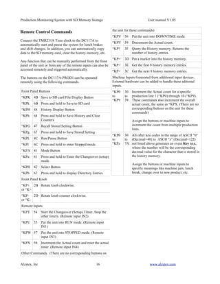
The document is a user manual for a Production TimeKeeper system that monitors production data and stores it in an SD memory card. It monitors up to 10 production lines simultaneously, tracking production counts, downtime, TAKT times and more. All monitored data is stored in an accessible history memory. It has buttons and remote inputs to control running, pausing and stopping production monitoring. The stored data includes production goals, actual counts, warnings and more.
Alarm Grid Home Security http://www.alarmgrid.com/ has provided this pdf with the permission and courtesy of Honeywell.
Alarm Grid is a home security product and alarm monitoring company that loves its customers. We have a strong appreciation of the DIY community, and want to make sure that we not only provide the best products and services out there but we also want to make sure that resources like these Honeywell product pdfs are easily accessible so that or curious customers can find what they need when they need it.
In This PPT we are discussed about complete details of that product (Use,Operation, Technical details, Dimensions, Wiring, and etc..)
Please Support us and Follow our other Sites
https://automationtechplc2.blogspot.com
https://humidificationcontrol.blogspot.com
https://controlsandsystems.business.site
If you enjoyed this article, share it with your friends and colleagues
Presentation of a paper at ISC 2008. Modification of a virtual TPM design to support more flexible key management and migration support for virtual machines.
Discover how to benefit from all the features on BeAnywhere’s inSight add-on. Prevent problems and downtimes from happening in your clients’ critical servers and workstations through Remote Monitoring and Managing tools.
An introduction to the product portfolio of temperature and process controllers, process indicators and transmitters from PMA (part of West Control Solutions)
사토프린터 SATO LT408 열전사감열 바코드프린터엔진 오토라벨러엔진 매뉴얼HION IT
SATO LT408 바코드 프린터 엔진은 “초급 수준”의 인쇄 적용 시장의 필요에 맞도록 디자인 및 제조되었습니다.
애플리케이터 시스템과 통합된 바코드 프린터 인쇄 엔진은 노동 집약적인 수동 라벨링이나 값비싼 사전 인쇄 상자 재고를 대체할 수 있는 저렴한 자동화 인쇄/적용 라벨링 솔루션으로, 낮은 처리량의 부하가 적은 애플리케이션을 제공합니다.
사토 LT408 오토라벨러 엔진은 통합 애플리케이터 인터페이스 포트와 서비스가 쉬운 구성 요소를 갖춘 진정한 OEM-스타일 프린터 입니다.
Large LCD Display Provides Greater Visibility.
Icon-Driven Interface Drives User-Friendly Operations
Right and Left Hand models
Fast and Easy to Change Printhead
Bi-Directional Ribbon Drive
Utilizes SATO Programming Language, The Industry Leader in Print & Apply Applications
Plug-in Interface Design for Communication Flexibility and SATO Multi-Platform Compatibility
Modular Design Allows Easy Integration with Several Applicators and Assures Fuss-Free Maintenance
PRINTING SPECIFICATIONS
Print Method : Direct Thermal/Thermal Transfer
Print Resolution : 8 dots/mm (203dpi)
Max Print Speed : 150mm/sec (6ips)
Max Print Area (W x P) : 104 x 1249mm (5” x 49.21”)
MEDIA SPECIFICATIONS
Sensor Type : Transmissive sensor for gap. Reflective sensor for I-mark.
Media Size :
Width: 10 to 112mm (0.39” to 4.41”), inclusive backing paper size 13 to 115 mm (0.51” to 4.53“)
Pitch: 15 to 1252mm (0.59” to 49.33”), inclusive backing paper size 18 to 1255 mm (0.71” to 49.45“)
Media (Thickness) : 0.08 to 0.26mm (0.003” x 0.01”)
Ribbon Size :
Width Max: 111mm (4.37”), Min: 25mm (0.99”)
Length Max: 450M, The max core diameter should be less than 78mm (3.07”)
Winding Direction Face-in and Face-out
Internal Diamater 25.6mm (1”)
COMMUNICATION INTERFACES
Selectable Plug-in Interface Cards RS-232C (25pin)
IEEE1284
USB
LAN
Wireless LAN (802.11g)
RS 422/485
Centronics
External Port Interface : 14 pins, 25 pins connector
FONTS/BARCODE SYMBOLOGIES
Internal Fonts : XU (5x9 dots), XS (17x17 dots), XM (24x24 dots), XB (48x48 dots),XL (48x48 dots), Outline Font, OCR-A (15x22 dots), OCR-B (20x24 dots)
Internal Raster Fonts : CG Times, CG Triumvirate
Barcodes :
1D Barcode : UPC-A/E, JAN8/13, NW-7, CODE 39, CODE 93, CODE 128, UCC/EAN 128, RSS-14, Inter-leaved 2 of 5, Industrial 2 of 5, Matrix 2 of 5, MSI, Postnet, Bookland
2D Barcode : QRCode, PDF 417, MaxiCode, Data Matrix, Synthetic Symbol
Character Rotation : 0º, 90º, 180º, 270º rotation
>하이온아이티
주소 : 서울 금천구 가산디지털2로 165, 1304호 (백상스타타워2차)
대표번호 : 02-2038-0018 / 이메일 : hion@hionit.com
홈페이지 : http://hionsmart.com
Information Server is much more than a web based portal, find out what else it can do for you.
Webinar Content:
Introduction to Information Server
Information Server's key capabilities
How to create reports
Licensing Structure
Short Demo
Reasons To Love The Web.
Wie Marken auf Basis eines starken Consumer Insight den Pain des Konsumenten lösen.
Mit einem adäquaten Einsatz von Technologie und einer sinnvollen, intelligenten Aufbereitung von Daten.
Hi friends
This PPT consist of automation information ,what is PLC,need of PLC applications,components of PLC ,PLC operations,Timers , Some Program, etc
instead of this it consists SCADA ,what is SCADA,need of SCADA,brands of SCADA, tags ,features of SCADA, Dynamic process graphic , script security etc.......
The Art of the Pitch: WordPress Relationships and SalesLaura Byrne
Clients don’t know what they don’t know. What web solutions are right for them? How does WordPress come into the picture? How do you make sure you understand scope and timeline? What do you do if sometime changes?
All these questions and more will be explored as we talk about matching clients’ needs with what your agency offers without pulling teeth or pulling your hair out. Practical tips, and strategies for successful relationship building that leads to closing the deal.
Key Trends Shaping the Future of Infrastructure.pdfCheryl Hung
Keynote at DIGIT West Expo, Glasgow on 29 May 2024.
Cheryl Hung, ochery.com
Sr Director, Infrastructure Ecosystem, Arm.
The key trends across hardware, cloud and open-source; exploring how these areas are likely to mature and develop over the short and long-term, and then considering how organisations can position themselves to adapt and thrive.
Let's dive deeper into the world of ODC! Ricardo Alves (OutSystems) will join us to tell all about the new Data Fabric. After that, Sezen de Bruijn (OutSystems) will get into the details on how to best design a sturdy architecture within ODC.
GraphRAG is All You need? LLM & Knowledge GraphGuy Korland
Guy Korland, CEO and Co-founder of FalkorDB, will review two articles on the integration of language models with knowledge graphs.
1. Unifying Large Language Models and Knowledge Graphs: A Roadmap.
https://arxiv.org/abs/2306.08302
2. Microsoft Research's GraphRAG paper and a review paper on various uses of knowledge graphs:
https://www.microsoft.com/en-us/research/blog/graphrag-unlocking-llm-discovery-on-narrative-private-data/
Builder.ai Founder Sachin Dev Duggal's Strategic Approach to Create an Innova...Ramesh Iyer
In today's fast-changing business world, Companies that adapt and embrace new ideas often need help to keep up with the competition. However, fostering a culture of innovation takes much work. It takes vision, leadership and willingness to take risks in the right proportion. Sachin Dev Duggal, co-founder of Builder.ai, has perfected the art of this balance, creating a company culture where creativity and growth are nurtured at each stage.
Epistemic Interaction - tuning interfaces to provide information for AI supportAlan Dix
Paper presented at SYNERGY workshop at AVI 2024, Genoa, Italy. 3rd June 2024
https://alandix.com/academic/papers/synergy2024-epistemic/
As machine learning integrates deeper into human-computer interactions, the concept of epistemic interaction emerges, aiming to refine these interactions to enhance system adaptability. This approach encourages minor, intentional adjustments in user behaviour to enrich the data available for system learning. This paper introduces epistemic interaction within the context of human-system communication, illustrating how deliberate interaction design can improve system understanding and adaptation. Through concrete examples, we demonstrate the potential of epistemic interaction to significantly advance human-computer interaction by leveraging intuitive human communication strategies to inform system design and functionality, offering a novel pathway for enriching user-system engagements.
Connector Corner: Automate dynamic content and events by pushing a buttonDianaGray10
Here is something new! In our next Connector Corner webinar, we will demonstrate how you can use a single workflow to:
Create a campaign using Mailchimp with merge tags/fields
Send an interactive Slack channel message (using buttons)
Have the message received by managers and peers along with a test email for review
But there’s more:
In a second workflow supporting the same use case, you’ll see:
Your campaign sent to target colleagues for approval
If the “Approve” button is clicked, a Jira/Zendesk ticket is created for the marketing design team
But—if the “Reject” button is pushed, colleagues will be alerted via Slack message
Join us to learn more about this new, human-in-the-loop capability, brought to you by Integration Service connectors.
And...
Speakers:
Akshay Agnihotri, Product Manager
Charlie Greenberg, Host
Neuro-symbolic is not enough, we need neuro-*semantic*Frank van Harmelen
Neuro-symbolic (NeSy) AI is on the rise. However, simply machine learning on just any symbolic structure is not sufficient to really harvest the gains of NeSy. These will only be gained when the symbolic structures have an actual semantics. I give an operational definition of semantics as “predictable inference”.
All of this illustrated with link prediction over knowledge graphs, but the argument is general.
Smart TV Buyer Insights Survey 2024 by 91mobiles.pdf91mobiles
91mobiles recently conducted a Smart TV Buyer Insights Survey in which we asked over 3,000 respondents about the TV they own, aspects they look at on a new TV, and their TV buying preferences.
UiPath Test Automation using UiPath Test Suite series, part 3DianaGray10
Welcome to UiPath Test Automation using UiPath Test Suite series part 3. In this session, we will cover desktop automation along with UI automation.
Topics covered:
UI automation Introduction,
UI automation Sample
Desktop automation flow
Pradeep Chinnala, Senior Consultant Automation Developer @WonderBotz and UiPath MVP
Deepak Rai, Automation Practice Lead, Boundaryless Group and UiPath MVP
UiPath Test Automation using UiPath Test Suite series, part 4DianaGray10
Welcome to UiPath Test Automation using UiPath Test Suite series part 4. In this session, we will cover Test Manager overview along with SAP heatmap.
The UiPath Test Manager overview with SAP heatmap webinar offers a concise yet comprehensive exploration of the role of a Test Manager within SAP environments, coupled with the utilization of heatmaps for effective testing strategies.
Participants will gain insights into the responsibilities, challenges, and best practices associated with test management in SAP projects. Additionally, the webinar delves into the significance of heatmaps as a visual aid for identifying testing priorities, areas of risk, and resource allocation within SAP landscapes. Through this session, attendees can expect to enhance their understanding of test management principles while learning practical approaches to optimize testing processes in SAP environments using heatmap visualization techniques
What will you get from this session?
1. Insights into SAP testing best practices
2. Heatmap utilization for testing
3. Optimization of testing processes
4. Demo
Topics covered:
Execution from the test manager
Orchestrator execution result
Defect reporting
SAP heatmap example with demo
Speaker:
Deepak Rai, Automation Practice Lead, Boundaryless Group and UiPath MVP
Accelerate your Kubernetes clusters with Varnish CachingThijs Feryn
A presentation about the usage and availability of Varnish on Kubernetes. This talk explores the capabilities of Varnish caching and shows how to use the Varnish Helm chart to deploy it to Kubernetes.
This presentation was delivered at K8SUG Singapore. See https://feryn.eu/presentations/accelerate-your-kubernetes-clusters-with-varnish-caching-k8sug-singapore-28-2024 for more details.
Slack (or Teams) Automation for Bonterra Impact Management (fka Social Soluti...Jeffrey Haguewood
Sidekick Solutions uses Bonterra Impact Management (fka Social Solutions Apricot) and automation solutions to integrate data for business workflows.
We believe integration and automation are essential to user experience and the promise of efficient work through technology. Automation is the critical ingredient to realizing that full vision. We develop integration products and services for Bonterra Case Management software to support the deployment of automations for a variety of use cases.
This video focuses on the notifications, alerts, and approval requests using Slack for Bonterra Impact Management. The solutions covered in this webinar can also be deployed for Microsoft Teams.
Interested in deploying notification automations for Bonterra Impact Management? Contact us at sales@sidekicksolutionsllc.com to discuss next steps.
Slack (or Teams) Automation for Bonterra Impact Management (fka Social Soluti...
Dc117 A Production Timer
1. Production Monitoring System with SD Memory Storage User manual V1.05
Monitor and Save Production Data
Production Monitoring With SD The Production TimeKeeperTM monitors production and
Memory Card Storage conveniently displays the results as a deviation, and
percentage between the production goal and the amount
actually produced. In addition to monitoring production the
The Production TimeKeeper TM Production TimeKeeperTM also tracks down-time, and other
critical time events like the number of times the TAKT time
TAKT timer with production counter and production expired. All of this data is stored in a conveniently accessible
statistic history storage that will monitor up to 10 history memory.
production lines simultaneously.
Recording User Events or Reason Codes
This reference guide covers the DC117A-PROD1 Firmware
Sometimes specific events occur that need to be recorded
Version V1.06 production monitoring system.
that are in addition to the standard events. This system
includes an external port to permit special events to be
recorded. For example: Machine jammed, out of material,
lunch break, fire drill, service door opened, or any other
event. The events can be entered manually or directly from a
machine output.
Buttons and Controls
The DC117A-PROD1 has the following buttons and
controls:
The main unit has 6 buttons and one knob.
The RJ11 jack on the side of the unit connects to
remote buttons or machine inputs for Run, Pause,
Stop and Next.
In addition, optional remote buttons or machine
inputs can be added for special events.
Front Panel Buttons
Programmable TAKT Timer and Scale Count
Traditionally, TAKT time is the time it takes to fabricate and Button Momentary Press and Press and Hold for 2
ship one product, and is established by dividing the number Name Release seconds
of orders in hand by the number of working hours in a day. Save Display SD Card File Save History Memory to
In addition to the programmable TAKT timer, the Name. SD Card.
Production TimeKeeperTM also contains a user-settable History Display history. Store history and reset
production counter to zero.
scale counter which allows the user to set the TAKT time to Recall Recall stored setting. Save stored setting.
the time it takes to fabricate product lots. Run/Pause/ Run/pause production Stop the Production Timer.
Stop counter
Processing lots. TAKT times of less than one second do not Mode Toggle display modes. Select various setup
choices.
work well with this system. When it takes less than one Select Cycle knob function. Display the directory entries
second to process one production unit, it is advisable to setup on the SD Memory card.
the system to process in lots. In this case, set the scale factor
to a standard lot size and set the TAKT time to the correct Table 2. DC117A-PROD1 button reference
time to process one lot.
Running or Static/Shift Goals
The Production TimeKeeperTM allows production
monitoring using running, or static/shift goals. The running
goal is calculated from the TAKT time and scale count while
the static, or shift goal is easily entered by the user.
Alzatex, Inc 1 www.alzatex.com
2. Production Monitoring System with SD Memory Storage User manual V1.05
- Momentary Pressing start puts system into RUNNING
Remote Inputs mode. Same as remote input two.
- Press and hold start puts system into STOPPED mode.
Remote inputs on the RJ-11 connector on the side of the unit
While in changeover mode:
Remote Operation Effect on Effect on Effect on Actual - Momentary Pressing start puts system into RUNNING
Input TAKT Setup Count
Timer Timer mode. Same as remote input two.
- Press and hold start puts system into STOPPED mode.
Input 1 Run runs pauses None Same as remote input three.
Input 2 Changeover pauses runs None
Input 3 Stop pauses pauses None
Input 4 Increment None None Increments the While in stopped mode:
(Next) count by the scale - Momentary Pressing start puts system into RUNNING
factor mode. Same as remote input two.
- Press and hold start puts system into STOPPED mode.
Table 3. Remote input function reference Same as remote input three.
Serial data Input
RS-422 Serial data input for input from additional devices of
input from a PLC or computer. A detailed list of commands
is described in the programming manual.
Serial data Output
RS-422 Serial data output for operating displays, and on
indicators, alarms, PLC or computer.
The remote inputs are ground closure type. The Run, Pause
and Stop inputs are typically connected to operator buttons.
The Increment (Next) button may be a button for the
operator or may be connected directly to a machine trigger.
Operating Modes
The system will be in one of the following operating modes:
Running. The TAKT timer is running.
Stopped. All timers are stopped.
Downtime. The TAKT timer is running and the
Down timer is running.
Changeover. The Setup timer is running.
While in stopped, downtime or changeover mode:
- Pressing start puts system into RUNNING mode. Same as
remote input one.
While in running mode:
- Momentary Pressing start puts system into DOWNTIME
mode. (PAUSE)
- Press and hold start puts system into CHANGEOVER
mode.
While in downtime mode:
Alzatex, Inc 2 www.alzatex.com
3. Production Monitoring System with SD Memory Storage User manual V1.05
Monitoring Production Statistics 4. Momentarily press the Mode button again. This display
serves one of two purposes depending on the system
The Production Timekeeper™ can display the current
configuration. By default, when using IN4 on the remote
production Data which is available on various screens.
port to increment the production count, these counters
Momentarily pressing the Mode button toggles between
show the production count for every hour of the day
the screens. The screen in step one is normally displayed
over a 24 hour period where 1=1AM, 2=2AM, etc
during production monitoring.
throughout the entire day. Alternatively, with additional
equipment to increment the production count, these
To display the current production data:
counters can keep track of the production counts from
multiple production lines. When counting production
1. Momentarily press the Mode button. A four-line
from multiple lines simultaneously, the actual count for
display similar to the following display will appear:
individual lines will be recorded. Another four-line
display similar to the following display will appear:
Goal nnnnnn HH:MM:SS
Act nnnnnn HH:MM:SS
Line Actual 4 98453
Dev nnnnnn Run Grn
1 2345 5 56232
Eff nnnn HH:MM:SS
2 2433 6 12987
3 9432 7 29845
Description
Line 1 – goal count; TAKT time (count down)
Description
Line 2 – actual count; actual time (count up)
Line 1 – Production Hour Actual or Line Actual
Line 3 – deviation; status (run/pause/stop)
Line 2 – Line number, Actual count
Line 4 – efficiency; time of day
Line 3 – Line number, Actual count
Line 4 – Line number, Actual count
2. Momentarily press the Mode button again. Another
four-line display similar to the following display will The individual production line counting feature requires
appear: either additional external hardware or connection to a PLC.
Setup Time HH:MM:SS
5. Momentarily press the Mode button again. This display
Accum Setup HH:MM:SS
DownTime HH:MM:SS shows the Grand totals for up to 24 production lines.
AccumDnTime HH:MM:SS Each time the actual counters are reset, the actual count
is added to the grand total. Another four-line display
similar to the following display will appear:
Description
Line 1 – Changeover (Setup) time for this event.
Totals: Goal Actual
Line 2 – Accumulated Changeover (Setup) time. 1 33241 151203
Line 3 – Down time for this event. 2 23447 12527
Line 4 – Accumulated Down time. 3 7922 61845
3. Momentarily press the Mode button again. Another Description
four-line display similar to the following display will Line 1 – Totals: Goal Actual
appear: Line 2 – Line number, Goal Count, Actual count
Line 3 – Line number, Goal Count, Actual count
Act nnnnnn HH:MM:SS Line 4 – Line number, Goal Count, Actual count
Blnk nnnnnn Downtime
Yel nnnnnn Pause The individual production line counting feature requires
Red nnnnnn SetClock either additional external hardware or connection to a PLC.
Analyzing and Improving productivity
Description
Line 1 – actual count; down time (count up)
There are three warning counts called Yellow Blink (Blnk),
Line 2 – Yellow blink count
Yellow Warning (Yel) and Red Warning (Red).
Line 3 – Yellow warning count
Line 4 – Red warning count (TAKT time expired)
Alzatex, Inc 3 www.alzatex.com
4. Production Monitoring System with SD Memory Storage User manual V1.05
SetClock Indicating that the time of day clock
needs to be set.
ClkError Indicating that there is a problem with
the TIME of day clock.
LowBatt Indicating that the battery needs to be
replaced. The battery can be replaced by
removing the rear cover and replacing the
battery with a new CR2032 coin cell type
battery.
These warnings can be used to indicate whether the actual
time is longer or shorter than the TAKT time and determine
whether there is a problem with production or whether a
particular operator is slower or faster or whether the TAKT
time is too long or too short.
Ideally, the TAKT time should be set such that the yellow
blink count and the yellow warning count increments the
same as the actual count, but that the Red warning count
always remains at zero.
The production workers can observe the Green-Yellow-Red
Andon indicators to determine whether they are ahead or
behind the expected TAKT time. These indicators are great
for Slide-Lines where several production workers need to
synchronize together.
The Yellow Blink (Blnk) warning indicates the
number of times the Yellow Blink time was reached
before the TAKT time expired to complete a
production unit. If the TAKT time is 100 seconds
and the Yellow Blink time is 20 seconds, then this
count will be incremented if it takes 80 or more
seconds to complete a production unit.
The Yellow (Yel) warning indicates the number of
times the Yellow Warning time was reached before
the TAKT time expired to complete a production
unit. If the TAKT time is 100 seconds and the
Yellow Warning time is 10 seconds, then this count
will be incremented if it takes 90 or more seconds
to complete a production unit.
The Red (Red) warning indicates the number of
times it took longer than the TAKT time to
complete a production unit.
The status field indicates the operational mode of the unit.
Pause
Stopped
Run Grn
Run Yel
Run Red
One of several error messages may appear on the lower right
corner of the display.
Alzatex, Inc 4 www.alzatex.com
5. Production Monitoring System with SD Memory Storage User manual V1.05
Save to History and Clear Counters command is
Storing and Resetting Production Data
executed.
The Production Timekeeper™ will save production data Event Description
each time the Production Timekeeper™ is reset. The events
0 Goal Production goal count. This can be either a
0 to 11 shown in table 1 are saved, and then the counters are
running, or static goal.
reset to zero and the timers are set to their preset values.
1 Act Actual production count. This can be
1. Press and Hold the History button. The following incremented manually, or by machine.
display will appear:
2 Dev Deviation count. (Goal – Actual).
Save to History 3 Eff Efficiency percent. (Goal/Deviation*100)
and Clear Counters
4 Down Accumulated Machine Down Time in
seconds.
5 Takt TAKT time in seconds.
2. Press and Hold the History button again. The 6 Time Actual Time since the most recent wigit
following display will appear: was started. This value is in seconds.
Goal nnnnnn HH:MM:SS 7 Red Red warning indicator count. This
Act 0 00:00:00 indicator occurs after the TAKT time has
Dev 0 Pause expired.
Eff 0 HH:MM:SS
8 Yel Yellow warning indicator count. This
indicator occurs during the TAKT time
prior to the red warning indicator. When
The Goal, Actual, Yellow Blink, Yellow Warning and Red this occurs is user-programmable.
Warning counters are set to zero. The Actual time and Down
time is reset to zero. The TAKT time is set to the preset 9 Blnk Yellow blink indicator count. This
value. indicator occurs during the TAKT time
prior to the red warning indicator. When
this occurs is user-programmable.
10 Time Actual count for the current hour
11 Tset Total accumulated changeover (Setup)
time in seconds.
12 ---- Reserved for future use.
13 Cgoa Goal Changeover (Setup) Time.
14 Cact Actual Changeover (Setup) time for the
current event.
15 Cdev Deviation between the goal and actual
changeover (Setup) time in seconds.
16 Ceff Efficiency of the current changeover
(Setup) time represented as a percentage.
17 ---- Reserved for future use.
Table 1. Production data reference 18 ---- Reserved for future use.
19 ---- Reserved for future use.
Stored Data 20 Gpre Current static/shift goal.
The following data can be stored. The time and date is saved 21 Scal Current scale factor.
along with each history entry.
The following events are recorded whenever one of the
The following events and/or data are stored whenever the
Alzatex, Inc 5 www.alzatex.com
6. Production Monitoring System with SD Memory Storage User manual V1.05
remote inputs Run, Pause, Stop or Next is activated. The
recording of these events can be individually enabled or
disabled using the Setup Event Save menu.
Event Description
22 Run The RUN mode was started. The value
field will be the downtime in seconds.
23 Paus The RUN mode was paused. The value
field will be the actual time in seconds.
24 Stop The RUN mode was stopped. The value
field will be the actual time in seconds.
25 Wigi A new unit is completed. The value field
will be the actual time in seconds to
complete this wigit.
Other Events.
Event Description
27 Save The history memory was saved to the SD
card. The value field contains the number
of entries stored.
28 Clr The history memory was cleared. The
value field contains the number entries in
the history memory at the time it was
cleared.
29 Key A remote “KPn command was received.
The 'n' is the value portion of the event.
30 Reserved for future use.
31 Rcll Recall a stored setting.
32 Sser Save data to external device connected to
the serial port.
33 Tgoa Grand total Goal Count
34 Tact Grand total Actual Count
35 --- Reserved for future use.
The following events and/or data are stored whenever the
Save to History and Clear Counters command is
executed.
The following values are recorded when storing the actual
counter values for production lines 1 through production
line 24. These actual counters are incremented when one of
the external “KP0 through “KP9 commands are received.
40-53 AC00 Actual count values for production line 1
to (40) through production line 10 (53).
AC23
54- --- Reserved for future use.
255
Alzatex, Inc 6 www.alzatex.com
7. Production Monitoring System with SD Memory Storage User manual V1.05
Clearing the History memory
To reset the production timers and counters:
3. Press and Hold the History button. The following
display will appear:
Save to History
and Clear Counters
4. Turn the Knob a number of clicks until the “Clear
History Memory” message appears in the
display.
5. Press and Hold the History button again. The
following display will appear:
Clear History Memory
Empty
The entire history memory is cleared. A single message is
added “Clr 341” where the number is the number of history
entries that was in the history memory before it was cleared.
Clearing the Grand Totals
To reset the production timers and counters:
6. Press and Hold the History button. The following
display will appear:
Save to History
and Clear Counters
7. Turn the Knob a number of clicks until the “Clear
Grand Totals” message appears in the display.
8. Press and Hold the History button again. The
following display will appear:
Clear Grand Totals
Empty
The grand totals are cleared. Two messages for each
production line that had an actual count greater than zero are
added to the history memory. The “Tgoa 12661” which is
the goal grand total count and .the “Tact 12962” which is the
actual grand total count .
Alzatex, Inc 7 www.alzatex.com
8. Production Monitoring System with SD Memory Storage User manual V1.05
Selecting the Static/Shift or Running Goal
Recalling Stored Production Data
Modes
The Production Timekeeper™ can recall stored production
data. The values shown in table 1 are monitored, and then The Production Timekeeper™ provides two different
stored each time the Production Timekeeper™ is reset: methods for management of Goal values:
Note: The Production Timekeeper™ has a history memory • In the running goal mode, the Production
of 4095 entries. This means that the Production Timekeeper™ calculates the running goal. It does
Timekeeper™ can often times store many days of this by adding the scale count to the goal count each
production data. time the takt time expires.
• In the static/shift goal mode, the user enters the desired
To recall production data: goal count as a preset value. In this mode, that value
does not change until the user reconfigures it.
1. Momentarily press the History button. A four-line
display similar to the following display will appear: In either mode, the DC117A-PROD1 will display the goal
count, the actual count, the calculated deviation between the
2008/01/12 14:03:45 goal and actual counts, and the calculated efficiency (the
0 Goal nnnnnn 9 percentage of actual production versus the production goal).
1 Act nnnnnn 12 The reader board displays the goal count, the actual count,
History 12 Of 156 and the efficiency.
NOTE: To select a running goal, the preset goal count must
Note: The first line is the date and time. The second and be set to 0. Any non-zero preset goal count will remain the
third lines are 2 lines of historical data. The fourth static goal value.. Only a preset goal count of zero changes
line is the number of history entries and the total the goal calculation mode of the Production Timekeeper™
number of history entries. from static/shift mode to running mode.
Turn the knob to scroll through the production history. As 1. When starting a new shift or new production run,
you scroll, the window will show 4 entries in sequence. It Press and hold the History button to clear the
helps to think of the 4-line display as a sliding window over counters and reset the timers.
the history memory that rolls over to the beginning when it 2. Momentarily press the Run/Pause/Stop button on
gets to the end. the DC117A-PROD1 unit or press the remote Run
button (remote input IN1) to start the TAKT, and
LOC Event Display Value Description.
actual timers. The TAKT timer will auto-restart
00 0 Save 76 when it expires.
01 4 Down 4398 3. Increment the production actual count by pressing
02 5 TAKT 122 the Next button (remote input IN4). See the
03 2007/10/22 08:22:54 line 1
04 1 Act 9 line 2
following Remote Inputs section for details.
03 4. For unscheduled production stoppages, machine
05 9 Grn 18 line 3 repairs or whenever you want downtime to
--
accumulate, pause the TAKT and actual timers by
06 History 4 of 156 line 4 momentarily pressing the Run/Pause/Stop button
07 0 Goal 44
08 6 Time 4567
on the DC117A-PROD1.
09 4 Down 4422 5. For Changeovers or other setups, press the remote
10 5 TAKT 288 Pause button (remote input IN2) .
. 6. Resume the timers by momentarily pressing the
.
.
Run/Pause/Stop button on the DC117A-PROD1,
31 or press the remote Run button (remote input IN1).
See the following Remote Inputs section for details.
NOTE: the Run/Pause/Stop button is labeled as
Run/Stop on the unit.
Alzatex, Inc 8 www.alzatex.com
9. Production Monitoring System with SD Memory Storage User manual V1.05
Note: Whenever the Production Timekeeper™ is in the 1. Momentarily press the Recall Setting button. The
changeover mode the TAKT and actual timers are following display will appear:
paused and the setup time timer starts running.
Setup Recall
Note: Whenever the Production Timekeeper™ is in the 3
downtime mode the downtime timer starts running. In --
addition, the TAKT timer continues to run.
When the unit is resumed the downtime and/or setup
timer is paused and the TAKT timer and actual timer is 2. Turn the knob to select the desired 0 to 7 setup.
resumed. 3. Momentarily press the Recall Setting button again to
recall the Production Timekeeper™ setup from the
7. For scheduled breaks or shift changes, Stop the selected storage location.
TAKT and actual timers without starting the
downtime timer pressing the press and holding the
Run/Stop button or press the remote Stop button Setting Up the Production Timekeeper™
(remote input, IN3).
The Production Timekeeper™ contains user programmable
timers and counters. Each programmable setting is selected
using the Mode button, and modified using the Select button
and the knob.
To setup the Production Timekeeper™:
User Programmable Presets Press and hold the Mode button. The following display
will appear:
The Production Timekeeper™ can save and recall 8 user
programmable setups. Each stored setup is labeled from 0 to Setup TAKT Time
7, and contains the following items: 0:00:14
--
1. TAKT time.
2. Goal value.
3. Scale factor.
Instructions
4. Yellow blink time.
Sets the TAKT timer.
5. Yellow warning time.
Turn knob to set seconds
6. Beeper mode.
Momentarily press the Select button
Turn knob to set minutes
To store a setup:
Momentarily press the Select button
Turn knob to set hours
1. Press and hold the Recall Setting button. The
following display will appear:
Momentarily press the Mode button. The following
Setup Store
3 display will appear:
--
Setup Goal
0
--
2. Turn the knob to select the desired 0 to 7 location.
3. Press and hold the Recall Setting button again to
store the current Production Timekeeper™ setup into
the selected storage location.
To recall a setup:
Alzatex, Inc 9 www.alzatex.com
10. Production Monitoring System with SD Memory Storage User manual V1.05
Instructions Instructions
Keep at 0 if a running goal is desired. If a static goal is The actual count increments by the scale count. The
desired, set this value to the desired goal. running goal calculation also uses the scale count. You
Turn knob to set goal in steps of 1 can select whether the actual count, the goal count or
Momentarily press the Select button both are affected by the scale factor. For instance, if
Turn knob to set goal in steps of 100 you have toe goal count, but not the actual count
Momentarily press the Select button selected, the goal will increment in steps of the scale
Turn knob to set goal in steps of 10000 factor, while the actual count increments in steps of
one.
Turn knob to set goal in steps of 1
Momentarily press the Select button
Turn knob to set goal in steps of 100
Momentarily press the Mode button. The following Momentarily press the Select button
display will appear: Turn knob to set goal in steps of 10000
Momentarily press the Select button
Setup Line Goal Turn knob to select whether the scale factor
0 affects the actual count, goal count, both or
-- neither.
Line 1 Momentarily press the Mode button. The following
display will appear:
Instructions
Keep at 0 if a running goal is desired. If a static goal is Setup Yel Warning
desired, set this value to the desired goal. 0:00:04
Turn knob to set goal in steps of 1
--
Momentarily press the Select button
Turn knob to set goal in steps of 100
Momentarily press the Select button Instructions
Turn knob to set goal in steps of 10000 Sets when the solid yellow occurs during TAKT time.
Momentarily press the Select button Turn knob to set seconds
Turn knob to select production line 2 Momentarily press the Select button
Repeat the above five steps for this line. Turn knob to set minutes
Repeat for subsequent lines until all lines are Momentarily press the Select button
setup. Turn knob to set hours
Momentarily press the Mode button. The following
display will appear: The yellow warning (solid yellow) occurs the set time
before the TAKT time expires. This is measured from
Setup Scale the start of the Actual timer, which is reset each time
1 the Actual count is incremented. For example: If the
-- TAKT time is set to 14 seconds, and the yellow
Goal Actual warning time is set to 4 seconds, the solid yellow
warning will occur 4 seconds before the TAKT time
NOTE: Do not set the scale to 0. If you set the Scale to 0, the expires which is 14-4, or 10 seconds into the Actual
Next button will never increment the actual count. time.
Momentarily press the Mode button. The following
display will appear:
Setup Yellow Blink
0:00:07
--
Alzatex, Inc 10 www.alzatex.com
11. Production Monitoring System with SD Memory Storage User manual V1.05
Instructions Instructions
Sets when the blinking yellow occurs during TAKT Sets up the date.
time. Turn knob to select the desired Day.
1. Turn knob to set seconds Turn knob to set year
2. Momentarily press the Select button Momentarily press the Select button
3. Turn knob to set minutes Turn knob to set Month
4. Momentarily press the Select button Momentarily press the Select button
5. Turn knob to set hours Turn knob to set Day
The Blinking Yellow warning occurs the set time
before the TAKT time expires. This is measured from Momentarily press the Mode button. The following
the start of the Actual timer, which is reset each time display will appear:
the Actual count is incremented. For example: If the
TAKT time is set to 14 seconds, and the Yellow Blink Setup Beep
time is set to 8 seconds, the Blinking Yellow warning Timer Zero
will occur 8 seconds before the TAKT time expires --
which is 14-8, or 6 seconds into the Actual time.
Instructions
Momentarily press the Mode button. The following Sets up the beeper mode.
display will appear: 1. Turn knob to select the desired mode
The choices are: Off
Setup Clock Timer Zero
0:00:00 On Warnings
-- Actual < Goal
DD117A0-V1.06 An optional external beeper must be installed for this
function to produce an audible sound.
Instructions
Sets up the time of day clock. If the Actual<Goal option is selected, the Red and Green
Turn knob to set hours Andon indicators operate differently. When the actual count
Momentarily press the Select button is greater than the goal count, the Green andon comes
Turn knob to set seconds on.When the actual count is less than the goal count, the Red
Momentarily press the Select button andon comes on.
Turn knob to set minutes
Momentarily press the Mode button. The following
NOTE: If the clock is running slow or fast, it can be display will appear:
calibrated to be within 2.5PPM in most cases. Contact
the factory for calibration information. Setup Event Save
Run Pause Stopped Wigit
NOTE: The product version number also appears on the --
bottom line of this menu. And Clear Counters Every Hr
Momentarily press the Mode button. The following
display will appear:
Setup YYYY/MM/DD
2008/01/01
--
Alzatex, Inc 11 www.alzatex.com
12. Production Monitoring System with SD Memory Storage User manual V1.05
Instructions Types of Data Output
Turn the knob until the desired selections appear. Turn the knob until the desired value 0 to 63 appears.
Save Run event. Each time the Run button 00 = Running or static goal.
(remote IN1) is pressed, an event is stored. 01 = Actual Count.
02 = Deviation (Goal – Actual).
Save Pause event. Each time the Pause 03 = Efficiency Percent (Goal/Deviation*100).
button (remote IN2) is pressed, an event is 04 = Accumulated Machine Down Time (Pause State).
stored. 05 = TAKT Time.
Save Stopped Event. Each time the Stop 06 = Actual Time to build one wigit (Running state).
button (remote IN3) is pressed, an event is 07 = Red Warning Count.
stored. 08 = Yellow Warning Count.
09 = Yellow Blink Count.
Save Wigit count event. Each time the Next 10 = Actual Count for the current hour.
button (remote IN4) is pressed, an event is 11 = Accumulated Setup/Changeover time.
stored. 12 = Not used.
“And Clear Counters” is a special feature that 13 = Goal Setup/Changeover Time for current event.
causes the counter values to be stored to 14 = Actual Setup/Changeover Time for current event.
internal memory at midnight. In addition, all 15 = Deviation Setup/Changeover Time (Goal –
the 24 individual production count counters Actual) for current event.
will be automatically reset at midnight. 16 = Efficiency Setup/Changeover Percentage.
“Every Hr” is a special feature that clears the 22 = Machine down time for current event.
individual hour counter that keeps track of the 17-63 = Spares for additional results.
hourly production count. If you are using the
multiple production line feature, the “Every The second entry is the display address. You can use any
Hr” feature should not be enabled. address here so long as it matches the address that is
configured into the display. See the display documentation
Momentarily press the Mode button. The following for configuring display addresses. The Addresses are in
display will appear: ASCII characters starting at '0' and going up to and including
'O'.
Setup Remote Display
00 Addr 1 Mode 0 Digits include 0-9.
-- Characters include A-O
Special characters include: :;<=>?@
Various types of information can be displayed on a large
display or reader board. This configuration menu selects Note: For example, the DSP1016A display default addresses
which data is transmitted on the serial port. are A, B, C, D for lines 1-4 respectively.
The first entry is the type of data to be displayed. The value
ranges from 00 to 63 as listed in the instructions below. The third entry is the number of digits displayed.
0 = Display data output disabled. Set all unused
data outputs to 0.
1 = 6 digit display. Displaying counter values 0
to 999,999 or time values in hours, minutes and
seconds.
2 = 4 digit display, right justified. Displaying
counter values 0 to 9,999 or time values in
minutes and seconds.
3 = 4 digit display left justified. Displaying
counter values in steps of 100 from 0 to
999,900 or time values in hours and minutes.
4 = Display short four character text string
representing the data value. For example goal
count will display “Goal”; actual count will
display “Act “; etc.
5 = Same as mode 1 except prefixed with a
displayed text string.
Alzatex, Inc 12 www.alzatex.com
13. Production Monitoring System with SD Memory Storage User manual V1.05
6 = Same as mode 2 except prefixed with a
displayed text string.
7 = Same as mode 3 except prefixed with a
displayed text string.
Momentarily press the Mode button. The following
display will appear:
Setup File Name
HISTA000.TXT
-
The file format is always A-Z for the first 5 characters and
000 to 999 for the last three characters. The numbers will
auto-increment each time data is stored. To change an
individual character in the File Name use a momentary
press of the Select button to move to the character position
then use the Knob to select the character value. To change
the file type between CSV and TXT, press the Select button
until cursor is under the file extension. Turn the Knob to
select the desired file type.
Instructions
- Turn the knob to select the desired character.
- Press the Select button to advance to the next
character
- Repeat until the desired file name is entered.
- The data may be stored in one of 2 formats plain text
(TXT) or Comma separated values (CSV).
Momentarily press the Mode button. The following
display will appear:
Setup Clear All
0:00:00
--
Instructions
Sets when the counters are cleared. The “And Clear
Counters” option must be enabled for this to work. The
default value is 00:00:00 which is midnight each day.
Turn knob to set hour
Momentarily press the Select button
Turn knob to set minute
The seconds cannot be changed.
.
Alzatex, Inc 13 www.alzatex.com
14. Production Monitoring System with SD Memory Storage User manual V1.05
Saving History to an SD Memory Card
HISTA023.TXT
The history memory can be stored on an SD (Secure Digital) 2007-10-10 06:29:57 Time 255
card. 2007-10-10 06:29:49 Down 714
2007-10-10 06:28:49 Save 77
2007-10-10 06:28:42 Scal 1
2007-10-10 06:28:42 Gpre 0
2007-10-10 06:28:42 Eff 55
2007-10-10 06:28:42 Dev -17
2007-10-10 06:28:42 Act 21
2007-10-10 06:28:42 Goal 38
2007-10-10 06:28:42 Grn 6
2007-10-10 06:28:42 Yel 6
2007-10-10 06:28:42 Red 5
HISTA024.CSV
“2007-10-10 06:28:27”,”Paus”,”241”
“2007-10-10 06:28:26”,”Run”,”539”
“2007-10-10 06:28:26”,”Paus”,”240”
Save to SD Card File “2007-10-10 06:27:49”,”Save”,”54”
HISTA000
“2007-10-10 06:27:10”,”Time”,”240”
Saved
Make sure that the SD card is inserted into the unit. Press the Displaying files on an SD Memory Card
Save button to see the name of the file to be saved to the SD
card. Press and hold the Save button to store the contents of The directory listing on an SD (Secure Digital) card.
the history memory on to the SD card. The history file name
will auto increment. The name in the display after the save is Files 1
completed is the name of the next file to be saved. You may HISTA000.CSV
remove the SD card from the unit and put it into any Size: 34232
computer that supports FAT12 or FAT16 type files. The
message “Saved” will appear once the save is completed.
Make sure that the SD card is inserted into the unit. Press
A single message is added to the history memory “Save 227” and hold the Select button to see the name of the file on the
where the number is the number of history entries that was in SD card. Turn the Knob to scroll through the list of files on
the history memory at the time the save was executed. the SD card.
See the example below for a sample of the saved data. When done, press any other button to exit this menu.
NOTE: If the SD card is not inserted, or if the card is not
formatted properly an error message “SD Card Error” will
appear on the display.
NOTE: Because all files are stored in the root directory of
the SD card only about 500 files can be stored (this is an SD
card limitation when used formatted for use with MS
Windows).
Typical data stored on the SD memory card.
Alzatex, Inc 14 www.alzatex.com
15. Production Monitoring System with SD Memory Storage User manual V1.05
door open, out of material, roller not turning, etc.
Remote Inputs Connect to a character generator device having a
video display monitor output.
To connect remote inputs to the Production Timekeeper™: Connect the input and output to a Web server that
generates web pages for displaying the production
1. Connect an RJ-11 wall plate jack to the Production data on the world wide web on on the plant intranet.
Timekeeper™ remote input jack using either a six The production data may be monitored by any
conductor modular crossover, or a six conductor authorized user that has a computer with a standard
modular standard telephone cord. web browser.
2. Connect a momentary (or push button) switch, or
switches between the desired remote input and ground
using the diagram (see installation instructions) as a
guide.
The remote inputs are used as follows:
IN-1 Put the timer into RUN mode. This is the
same as pressing the RUN/PAUSE/STOP
button.
IN-2 Put the timer into PAUSE mode. This is
the same as pressing the RUN/PAUSE/STOP
button.
IN-3 Put the timer into STOPPED mode. This
is the same as pressing and holding the
RUN/PAUSE/STOP button.
IN-4 Increment the Actual Count. It also resets
the actual count timer. This is labeled the Next
button on the remote button module.
Note: As the diagram (in the installation instructions)
portrays, the individual colored wires on the RJ-11 wall
plate jack will function differently depending which six
conductor modular telephone cord is chosen.
Remote Serial Input
Remote serial devices may be connected to the serial input
on the Production Timekeeper™.
This unit has an RS422 connector for serial data input.
The RJ-45 connectors can be used for RS-422 serial
data.
This unit can be connected to an Alzatex input device, PLC,
Computer or any device having a serial port. The data OUT
is typically the display data. The data IN may be used to
generate events or to control the unit remotely. Some of the
options include:
Connect a remote button module to the RS422 input
for generating special events. Assign the buttons to
specific meanings like machine jam, lunch break,
change over to new product, etc.
Connect to a TMR231A Time clock to
automatically start and pause the system for lunch
brakes and shift changes.
Connect the output of a PLC that has a serial output
or other machine outputs to a ground closure to
serial adapter to record specific machine events like
Alzatex, Inc 15 www.alzatex.com
16. Production Monitoring System with SD Memory Storage User manual V1.05
the unit for these commands)
Remote Control Commands
“KPV 56 Put the unit into DOWNTIME mode.
Connect the TMR231A Time clock to the DC117A to
“KPY 59 Decrement the Actual count.
automatically start and pause the system for lunch brakes
and shift changes. In addition, you can automatically copy “KP? 3F Query the History memory. Returns the
data to the SD memory card, clear the history memory, etc. number of history entries.
“KP= 3D Put a marker into the history memory.
Any function that can be manually performed from the front
panel of the unit or from any of the remote inputs can also be “KP> 3E Get the first 8 history memory entries.
accessed remotely and triggered automatically. “KP< 3C Get the next 8 history memory entries.
The buttons on the DC117A-PROD1 can be operated Machine Inputs Generated from additional input devices.
remotely using the following commands. External hardware can be added to handle these aditional
inputs.
Front Panel Buttons “KP0 30 Increment the Actual count for a specific
“KPK 4B Save to SD card File Display Button to to production line 1 (“KP0) through 10 (“KP9).
“KP9 39 These commands also increment the overall
“KPk 6B Press and hold to Save to SD card actual count, the same as “KPX. (There are no
“KPH 48 History Display Button corresponding buttons on the unit for these
commands)
“KPh 68 Press and hold to Save History and Clear
Counters Assign the buttons or machine inputs to
“KPG 47 Recall Stored Setting Button increment the count from multiple production
lines.
“KPg 67 Press and hold to Save Stored Setting
“KP0 30 All other key codes in the range of ASCII “0”
“KPL 4C Run/Pause Button to to (Decimal=48) to ASCII “z” (Decimal=122)
“KPl 6C Press and hold to enter Stopped mode. “KPz 7A not listed above generates an event Key xxx,
where the number will be the corresponding
“KPA 41 Mode Button decimal value for the character that is stored in
“KPa 61 Press and hold to Enter the Changeover (setup) the history memory.
mode.
Assign the buttons or machine inputs to
“KPB 42 Select Button specific meanings like machine jam, lunch
“KPb 62 Press and hold to display Directory Entries break, change over to new product, etc.
Front Panel Knob
“KP+ 2B Rotate knob clockwise.
or “K+
“KP- 2D Rotate knob counter clockwise.
or “K-
Remote Inputs
“KPT 54 Start the Changeover (Setup) Timer, Stop the
other timers. (Remote input IN2)
“KPU 55 Put the unit into RUN mode. (Remote input
IN1)
“KPW 57 Put the unit into STOPPED mode. (Remote
input IN3)
“KPX 58 Increment the Actual count and reset the actual
timer. (Remote input IN4)
Other Commands. (There are no corresponding buttons on
Alzatex, Inc 16 www.alzatex.com
17. Production Monitoring System with SD Memory Storage User manual V1.05
Wiring
To connect remote inputs to the Production Timekeeper™:
Connect a RJ-11 wall plate jack to the Production
Timekeeper™ remote input jack using either a six
conductor modular crossover, or a six conductor
modular standard telephone cord.
Connect a momentary (or push button) switch, or
switches between the desired remote input and ground
using the following diagram as a guide.
Note: As the diagram portrays, the individual colored
wires on the RJ-11 wall plate jack will function
differently dependent on the six conductor
modular telephone cord chosen.
Red 6 conductor 6 conductor
White modular Xover modular Std
Yellow
3-RD 1-WH 5-YL
(6) Blue (6) Increment (6) Run
(5) Yellow (5) Stop (5) +V
(4) Green (4) Ground (4) Pause
(3) Red (3) Pause (3) Ground
(2) Black (2) +V (2) Stop
(1) White (1) Run (1) Increment
4-GN 6-BL 2-BK
Black
Blue
Green
Alzatex, Inc 17 www.alzatex.com