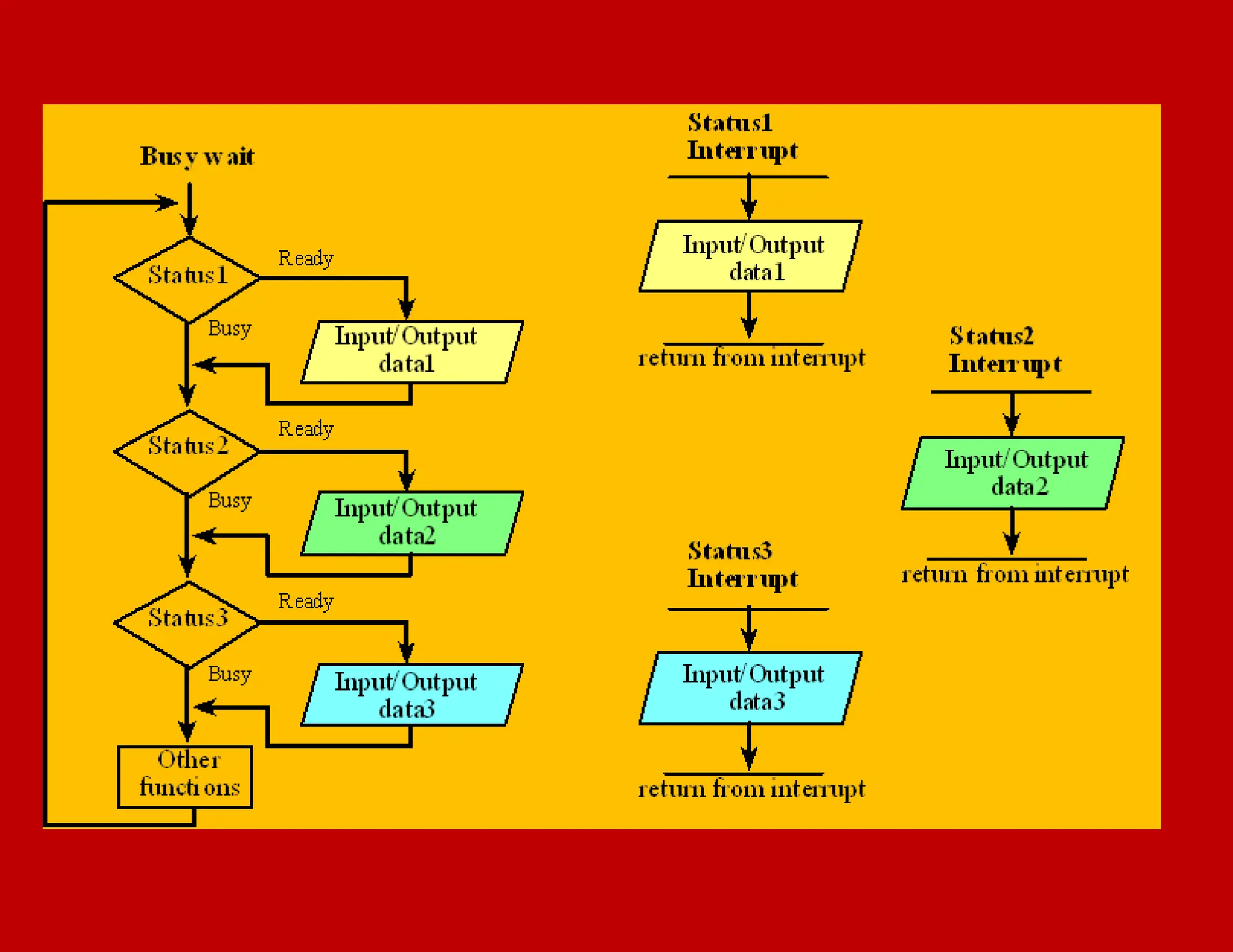
DEVICE DRIVERS AND INTERRUPTS SERVICE MECHANISM.pdf
1. DEVICE DRIVERS AND INTERRUPTS SERVICE
MECHANISM
Programmed I/O (busy and wait) method for ports
and devices, and the need for interrupt driven IOs
1
2. An embedded system uses its input/output devices to interact
with the external world. Input devices allow the computer to
gather information, and output devices can display
information. Output devices also allow the computer to
manipulate its environment. The tight-coupling between the
computer and external world distinguishes an embedded
system from a regular computer system. The challenge is under
most situations the software executes much faster than the
hardware. E.g., it might take the software only 1 us to ask the
hardware to clear the LCD, but the hardware might take 1 ms
to complete the command. During this time, the software could
execute tens of thousands of instructions. Therefore, the
synchronization between the executing software and its
external environment is critical for the success of an embedded
system.
3.
4. Interrupt Concepts
An interrupt is the automatic transfer of software
execution in response to a hardware event that is
asynchronous with the current software execution. This
hardware event is called a trigger. The hardware event
can either be a busy to ready transition in an external I/O
device (like the UART input/output) or an internal event
(like bus fault, memory fault, or a periodic timer). When
the hardware needs service, signified by a busy to ready
state transition, it will request an interrupt by setting its
trigger flag.
5. A thread is defined as the path of action of software as it
executes. The execution of the interrupt service routine is
called a background thread. This thread is created by the
hardware interrupt request and is killed when the interrupt
service routine returns from interrupt (e.g., by executing a BX
LR). A new thread is created for each interrupt request. It is
important to consider each individual request as a separate
thread because local variables and registers used in the
interrupt service routine are unique and separate from one
interrupt event to the next interrupt.
6. In a multi-threaded system, we consider the threads as
cooperating to perform an overall task. Consequently, we
will develop ways for the threads to communicate (e.g.,
FIFO) and to synchronize with each other. Most embedded
systems have a single common overall goal. On the other
hand, general-purpose computers can have multiple
unrelated functions to perform.
7. A process is also defined as the action of software
as it executes. Processes do not necessarily
cooperate towards a common shared goal. Threads
share access to I/O devices, system resources, and
global variables, while processes have separate
global variables and system resources. Processes do
not share I/O devices.
8. Programmed IOs approach from ports and devices
⢠Processor is continuously busy in
executing the program related to input
or output from the port and waits for
the input ready or output completion
⢠Processor is continuously busy in
executing the program related to device
functions and waits for the device status
ready or function completions
8
9. Exampleâ A 64-kbps UART Input
â˘When a UART transmits in format of 11-bit per character
format, the network transmits at most 64 kbps ď¸ 11 = 5818
characters per second, which means every 171.9 ďs a
character is expected.
â˘Before 171.9 ďs, the receiver port must be checked to find
and read another character assuming that all the received
characters are in succession without any in-between time-
gap
9
11. Ports A and B with no interrupt generation and interrupt
service (handling) mechanism
â˘Port A be in a PC, and port B be its modem input which
puts the characters on the telephone line.
â˘Let In_A_Out_B be a routine that receives an input-
character from Port A and re-transmits the character to Port
B output.
11
12. In_A_Out_B routine
12
⢠Has to cyclically call the following steps a to e and
executes the cycles of functions i to v, thus ensuring the
modem port A does not miss reading the character
13. In_A_Out_B routine
â˘Call function i
â˘Call function ii
â˘Call function iii
â˘Call function iv
â˘Call function v
â˘Loop back to step 1
13
14. Steps a, b and c
14
⢠Step a: Function iâ Check for a character at port A, if
not available, then wait
⢠Step b: Function iiâ Read Port A byte (character for
message) and return to step a instruction, which will
call function iii
⢠Step c: Function iiiâ Decrypt the Message and return
to step a instruction, which will call function iv
15. Steps d and e
15
⢠Step d: Function ivâ Encode the Message and return to
step a instruction, which will call function v.
⢠Step e: Function v â Transmit the encoded message to
Port B and return to step a last instruction, which will
start step a from beginning
16.
17. Step a
17
⢠Does Pollingâ Polling a port means to find the status
of the portâ whether ready with a character (byte) at
input or not.
⢠Polling must start before 171.9 ďs because characters
are expected at 64 kbps/11 bit format.
18. Condition in which no character misses
18
⢠If the program instructions in four steps b, c, d and e
(functions ii to v) take total running time of
less than 171.9 ďs then the above programmed IO
method works.
19. Problems with Programmed IOs approach from ports
and devices
1. (a) The program must switch to execute the
In_A_Out_B cycle of steps a to e within a
period less than 171.9 ďs. (b) Programmer
must ensure that steps of In_A_Out_B and any
other device program steps never exceed this
time.
19
20. Problems with Programmed IOs approach from port as
and devices
2. When the characters are not received at Port A
in regular succession, the waiting period during
step a for polling the port can be very
significant.
3. Wastage of processor times for the waiting
periods is the most significant disadvantage
of the present approach
20
21. Problem with Programmed IOs approach from ports and
devices
21
4. When the other ports and devices are also present, then
programming problem is to poll each port and device, and
ensure that program switches to execute the In_A_Out_B step
a as well as switches to poll each port or device on time and
then execute each service routines related to the functions of
other ports and devices within specific time intervals such that
each one is polled on time.
22. Problems with Programmed IOs approach from ports and
devices
5. The program and functions are processor and
device specific in the above busy-wait approach,
and all system functions must execute in
synchronization and timings are completely
dependent on periods of software execution
22
23. IO based on an interrupt from Port A
23
⢠Instead of continuously checking for characters at the port A by
executing function (i) we can first call step a when a modem
receives an input character, sets a status bit in its status register and
interrupts Port A. The interrupt should be generated by port
hardware.
⢠In response to the interrupt, an interrupt service routine ISR_ PortA
_Character executesâ an efficient solution in place the wait at step a
(poll for input character)
24. Application of programmed IOs
24
⢠In case of single purpose processor and dedicated IOs or
device functions with continuous device status polling
26. ⢠Interrupt means event, which invites attention of the
processor on occurrence of some action at hardware or
software interruptinstruction event.
26
Interrupt Concept
27. Action on Interrupt
27
⢠In response to the interrupt, the routine or program,
which is running presently interrupts and an interrupt
service routine (ISR) executes.
28. Interrupt Service Routine
28
⢠ISR is also called device driver in case of the devices
and called exception or signal or trap handler in case of
software interrupts
29. Interrupt approach for the port or device functions
⢠Processor executes the program, called
interrupt service routine or signal
handler or trap handler or exception
handler or device driver, related to input
or output from the port or device or
related to a device function on an
interrupt and does not wait and look for
the input ready or output completion or
device-status ready or set
29
30. Hardware interrupt
30
⢠Examplesâ When a device or port is ready, a device or
port generates an interrupt, or when it completes the
assigned action or when a timer overflows or when a
time at the timer equals a preset time in a compare
register or on setting a status flag (for example, on timer
overflow or compare or capture of time) or on click of
mice in a computer
⢠Hardware interrupt generates call to an ISR
31. Software Interrupt
31
Examples
â˘When software run-time exception condition (for examples,
division by 0 or overflow or illegal opcode detected) the processor-
hardware generates an interrupt, called trap, which calls an ISR
⢠When software run-time exception condition defined in a
program occurs, then a software instruction (SWI) is executedâ
called software interrupt or exception or signal, which calls an
ISR .
32. Software Interrupt
32
⢠When a device function is to be invoked, for example,
open (initialize/configure) or read or write or close ,
then a software instruction (SWI) is executedâ called
software interrupt to execute the required device driver
function for open or read or write or close operations.
33. Interrupt
33
⢠Software can execute the software instruction (SWI) or Interrupt n
(INT n) to signal execution of ISR (interrupt service routine). The n
is as per the handler address.
⢠Signal interrupt [The signal differs from the function in the sense
that execution of signal handler (ISR) can be masked and till mask
is reset, the handler will not execute on interrupt. Function on the
other hand always executes on the call after a call-instruction.]
34. Interrupt Driven Actions
On Interrupt Interrupt Service
Routine (ISR)
Running
Program Return
No continuous checks of device status
34
35. How does call to ISR differ from a function
(routine) call?
35
36. Routine (function) and ISR call features
36
⢠On a function call, the instructions are executed from a
new address
⢠Execute like in as function in the âCâ or in a method in
Java.
⢠ISR also the instructions are executed from a new
address like in as function in the âCâ or in a method in
Java
37. Routine (function) call and ISR call features
37
⢠A function call is after executing present instruction in any
program and is a planned (user programmed) diversion from the
present instruction in sequence of instructions to another
sequence of instructions; this sequence of instructions executes
till the return from that.
⢠An ISR call is after executing present instruction in any program
and is interrupt related diversion from the current sequence of
instructions to another sequence of instructions; this sequence of
instructions executes till the return from that or till another
interrupt of higher priority
38. Nesting of function calls and ISRs
38
⢠Nesting the function-calls â When a function 1 calls
another function 2 and that call another function 3,
on return from 3, the return is to function 2 and
return from 2 is to function. Functions are said to be
nested
⢠The ISR calls in case of multiple interrupt occurrences
can be nested or can be as per priority of the
interrupts
39. Using the Interrupt(s) and ISR(s) for each device
function (for example, read, write)
- Use of ISRs (Interrupt Service Routine) by SWIs
is the main mechanism used for the device accesses
and actions
39
40. Interrupt driven IO and device accesses feature
1. There is no continuous monitoring of
the status bits or polling for status by
the application.
2. Between two interrupt calls the program
task(s) continue. There are many
device- functions, and each of which
executes on a device interrupt.
40
41. Exampleâ A 64-kbps UART Input
â˘When a UART transmits in format of 11-bit per
character format, the network transmits at most 64
kbps ď¸ 11 = 5818 characters per second, which
means every 171.9 ďs a character is expected.
â˘Before 171.9 ďs, the receiver port is not checked.
Only on interrupt from the port the character is read
â˘There is no in-between time-gap for polling
41
42. Ports A and B with interrupt generation and interrupt
service (handling) mechanism
⢠Port A be at in a PC, and port B be its modem input
which puts the characters on the telephone line.
⢠Let ISR_ PortA_Character be a routine that receives an
input character from Port A on interrupt and Out_B
routine re-transmits an output character to Port B.
42
43. ISR_ PortA _Character
43
⢠Step f function (vi): Read Port A character. Reset the
status bit so that modem is ready for next character input
(generally resetting of status bit is automatic without need
of specific instruction for it). Put it in memory buffer.
Memory buffer is a set of memory addresses where the
bytes (characters) are queued for processing later.
⢠Return from the interrupt service routine.
44. 2008
Chapter-4 L02: "Embedded Systems - " , Raj Kamal,
Publs.: McGraw-Hill Education
20
ISR_ PortA _Character
On interrupt call ISR_ PortA _Character
Save PC, status word and registers (current
program context) on stack
Step f
Execute function vi codes (read character,
reset port status bit, character save in
memory buffer)
Return (retrieve the saved context)
Current program
45. Out_B routine
45
⢠Step g: Call function (vii) to decrypt the message
characters at the memory buffer and return for next
instruction step h.
⢠Step h: Call function (viii) to encode the message
character and return for next instruction step k
⢠Step k: Call function (ix) to transmit the encoded
character to Port B
⢠Return from the function.
46. Out_B Routine
Out_B Routine
Step g
Step h
Step k
Each step has three parts, save context, execute
codes, and retrieve the context for return 46
47. Application of Interrupt based IOs and device functions
⢠In case of multiple processes and
device functions with no device
status polling or wait
47
48. Use of ISR in the mobile phone reset key interrupt
example
Mobile
Keypad
events
input
processor
at mobile
Event: Reset
Key pressed
to reset the
mobile
ISR_ResetKey Read
key state at Port bits
P0-P7 Reset key state
status bit
Sent message for
tasks
Signal timer start for
enabling display off
after 15 s (preset
time)
P0-P7
Reset event
1 2
Call
4
Signal timer Tasks
4
Data bus
5
R
et
ur
n
Interrupt
3
Sent
messag
e for
Tasks
48
50. Software Interrupt (Throw an Exception) Concept
⢠A program needs to detect error condition
or run time exceptional condition
encountered during the running.
⢠In a program either the hardware detects
this condition or in a program detects this
condition, then an instruction SWI
(software interrupt) is used
5
0
51. Detection of exceptional run-time condition
â˘Called throwing an exception by the program.
â˘An interrupt service routine (exceptional handler
routine) executes, which is called catch function as it
executes on catching the exception thrown.
5
1
52. SWI
â˘Executes on detecting the exceptional run- time condition
during computations or communication.
â˘For example, on detecting that the square root of a
negative number is being calculated or detecting illegal
argument in the function or detecting that connection to
network not found.
5
2
53. Example: SWI a1 and SWI a2
5
3
⢠The SWI (software interrupt) instructions,
SWI a1 and SWI a2 will be inserted for
trapping (A- B) as âve number and trapping
y > 100 or less than 0
54. Software instruction SWI a1
5
4
⢠Causes processor interrupt.
⢠In response, the software ISR function
âcatch (Exception_1 a1) { }â executes
on throwing of the exception a1 during
try block execution.
⢠SWI a1 is used after catching the exception
a1 whenever it is thrown
55. Software instruction SWI a2
5
5
⢠Causes processor interrupt.
⢠In response, the software ISR function
âcatch (Exception_2 a2) { }â executes
on throwing of the exception a1 during
try block execution.
⢠SWI a2 is used after catching the exception
a2 whenever it is thrown
56. 2008 Chapter-4 L03: "Embedded Systems - " , Raj
8
Use of SWI software interrupt-instruction for calling an ISR
in the software on throwing and catching the exceptional run-
time conditions a1 and a2 encountered during computations
Exceptional handler
Find exception source a1
Run codes for actions to
be taken on event a1 in
catch (Exception_1 a1) {
}
Find exception source a2
Run codes for actions to
be taken on event a2 in
catch (Exception_1 a2{ }
Call function to execute at
end
Call function to
execute
end
on detecting
an
exception
condition or
error
condition in
try block
End of
Function
Run Codes at
finally { âŚ}
codes, which
should
execute when
the
exceptions or
try
bl
ock
instructions
finished
Status Flags for the Exception sources in the memory
throw
event a1
Software
interrupt
throw
event a2
Software
interrupt
on detecting
another
exception
condition or
error condition
in try block
1
2
57. SWI a3
57
⢠Software ISR function âfinally { }â
executes either at the end of the try or at the
end of catch function codes.
⢠SWI a3 is used after the try and catch
functions finish, then finally function will
perform final task, for example, exit from
the program or call another function
58. Signal from a thread for Signal handler Interrupt Service
Routine
⢠ISR is also called signal handler in case of a
routine or program thread, or task sends a signal
using an SWI
⢠Signals are used to notify error conditions or
notifying end of an action to enable signal
handler thread or task to initiate action on that.
58
59. Action on Signal generated by SWI and signal handling
A program or task or
routine 1
Run Codes
Signal (event e1) for run
routine 2
Status Flags for the Signal sources
in the memory
interrupt
A program or task or
routine 2
Run Codes
Signal (event e2) for
run routine 3
Software
interrupt 1
Software
2
Signal handler Find signal
a1
Run codes for actions to be
taken on signal a1 from
program
Find signal a2
Run codes for actions to be
taken on signal a2 from program to
execute at end
59
60. Device driver
60
⢠Does the interrupt service for any event related to the
device and use the system and IO buses required for the
device service.
⢠Device driver can be considered software layer
between an application program and the device
61. Interrupt service routines
61
⢠An Interrupt service routine (ISR) accesses a device for
service (configuring, initializing, activating, opening,
attaching, reading, writing, resetting, deactivating or
closing).
⢠Interrupt service routines thus implements the device
functions of the device driver
62. First level ISR and second level IST approach to
handle the device hardware interrupts followed by
software interrupt
Command
c1
Device driver
command 1 Run
short code Signal
ISR 1
Device driver
command 2 Run
short code Signal
ISR 2
Command
c2
Interrupt
Interrupt (signal)
Interrupt (signal)
ISR 1
Run codes of
device function 1
ISR 2
Run codes of
device function 2
device
event e3
Interrupt
Interrupt
62