This document discusses hard disk interfaces, specifically the Enhanced Small Device Interface (ESDI) and the AT Attachment (ATA) interface, commonly known as IDE.
ESDI was developed in 1983 as an intelligent successor to the ST412/506 interface. It integrated the data separator onto the drive itself rather than a separate controller. An ESDI controller could pass complete commands to the drive for decoding and execution.
The ATA/IDE interface was developed in the mid-1980s as a lower-cost alternative that integrated the controller directly onto the drive. It uses a simple 40-pin interface and cable to connect up to two drives to the system. The interface presents the drives to the operating system like conventional
![r
Chapter 3] . Hard Disk Drives
883
wires between the plug in the middle and the end of the cable (s
drives) do exist. But, "~1:1-~ n bDUl Is designed for a transfer rate of up to 24 Mbits/s between drive and controller; typically
select 3 and drive select 4 are not used, so you may 10-15 Mbits/s are achieved. ESDI hard disks use the RLL method for data encoding. Further-
more, an ESDI controller is Intended for connecting up to seven ESDI drives, and may access
Of all hard disk interfaces used on the PC, the ST412/506 Is the least «intelligent». It is a pure ^ard disks with a maximum of 64 heads In four groups of 16 heads each, as well as a maximum
signal Interface, thus the controller Is unable to pass any command to the drive. The drive Itself of 4096 cylinders. The controller of Its predecessor Interface (ST412/506), on the other hand,
accommodates only the control circuitry for stabilizing the disk rotation and the head position- allowed a maximum of only 16 heads and 1024 cylinders.
ing. All other control functions are carried out by the controller Itself, for example, Interpretation
of the commands from the PC system, the encoding and decoding of the read and write data, An ESDI controller may also pass complete commands which are decoded and executed by the
the generation of address marks, etc. drive. On the other hand, the generation of address marks, synchronization pattern and the
decoding of the NRZ into parallel bit data for the PC system bus are carried out by the control-
ST412/506 controllers and drives were used first in the XT, and later also in the AT. Because the ler. Thus an ESDI controller Is neither a pure controller which takes over all control functions,
XT BIOS was not designed as standard for the support of hard disks, all XT controllers must nor a host adapter which solely establishes a connection to the system bus; instead, it Is some-
have their own BIOS with the hard disk functions of INT 13h. The start address of this BIOS thing like an intermediate product between controller and host adapter. ESDI signals and ESDI
extension Is usually c8000h. The AT, on the other hand, supported hard disks from the first day, commands will not be discussed here because the interface Is already outdated.
and the required routines are already Implemented In the system BIOS at address fOOOOh. But For the connection of ESDI hard disks, in principle the same rules as for an ST412/506 drive
there are other differences between XT and AT controllers with an ST412/506 Interface: apply. First you must configure the drives, that Is, adjust their ESDI address. Because of the
different uses of the cable wires and the binary encoding of the drive address on the control
- The XT controller uses DMA channel 3 for transferring data between sector buffer and main
cable, no cables with twisted wires are available for ESDI to free you from this drive configu-
memory; In the AT, on the other hand, the BIOS carries out a programmed I/O by means
of the port instructions IN and OUT without using any DMA channel ration. With ESDI you always need to assign every drive an ESDI address. However, It Is not
significant here which plug of the control cable you connect with which ESDI drive.
- The XT controller employs IRQ5 for Issuing a hardware interrupt; the AT controller IRQ14.
- The XT controller is accessed via the XT task file, the AT controller via the AT task file; the
register assignment and addresses of these +™m t-^v &~~ _..«vucx via me AI tasK tile;
_ ----
icgwiei assignment and addresses of these two task files are Incompatible; drivers for XT 31.6 Drives with IDE, AT Bus or ATA Interface
hard disk controllers with an ST412/506 interface cannot be used for an AT controller.
The commands for an XT controller always consist of a 6-byte command block to a single Recently, a new hard disk interface standard was established for PCs which is overtaking the
register; several -—^^^x, on the other is programmed by means of single command
bytes to the AT controller, registers. hand, k r»rr»n-^~™-j *-
individual ST412/506 standard more and more: the so-called IDE or AT bus interface. IDE Is the abbrevia-
tion for intelligent drive electronics ~ an Indication that the connected drives are intelligent on
their own. With the conventional controller-hard disk combination, the drive itself has only
Connecting and Confii those electronic elements required to drive the motors and gates of the drive. The more exten-
luring ST412/506 Hard Disk Drives
sive control for executing commands (for reading a sector, for example, a head seek, the reading
The of the encoded signals, the separation of data and clock signal, the transfer into main memory,
etc. must be carried out) Is taken over by the electronic equipment on a separate adapter, that
the control cable, an eventual second h d di kto h ^ ** ^ ** t0 *" ™ d ° f is, the hard disk controller. Thus the drive itself is rather «stupid». A further disadvantage of
a control cable without twisted w^ Aen on T"**" " ** ^ ff >™ a r e u s i n § this solution Is that the still encoded signals must run from the drive via the data cable to the
drive select 1 by m e a n s o f t h e ^ s o ^ d l ^ * G M *** 8ekct ° a n d * * * D : a s controller to be decoded there. The transfer path worsens the signals; a high data transfer rate
cable with twisted wires then y o u Z c o t f ' T ^ * * ^3S " y ° U a r e U s i n § a «>"** between drive and controller falls because of the relatively long signal paths. Further, the ex-
for floppy drive, B e c a u s e ^ Sof^l l eT e ^c t^ ^
t s Ie
*** "** h as JL the case ploding market for hard disk drives gave rise to a nearly infinite variety of drive geometries and
enabled. exchange signals, the intended disk is always storage capacities, so that a separate controller (which possibly comes from a third-party manu-
facturer) Is simply overtaxed to serve all hard disk formats.
3 1 ! 3 The ESDI int@ The falling prices for electronic equipment during the past few years, in parallel with a remark-
able performance enhancement, gave a simple solution: modern and powerful hard disk drives
already integrate the controller, and It Is no longer formed by a separate adapter card. The
ESDI was conceived by Maxtor In 1983 as a powerful and intelligent successor to the ST412/506
signal paths from disk to controller are thus very short, and the controller can be adapted In an
interface. The main problem of the long transfer distances between hard disk and data separ-
optimized way to the hard disk It actually controls. The IDE and SCSI Interfaces follow this
ator was solved, In that ESDI already Integrates the data separator on the drive.
I of integrating drive and controller into a single unit. But SCSI has another philosophy](https://image.slidesharecdn.com/ide-100104082519-phpapp01/85/Ide-1-320.jpg)
![887
Chapter] Hard Disk Drives
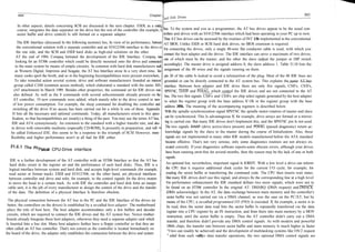
IDE signal pjn
Signal meaning implemented in the new IDE standard. Some AT bus hard disks can be instructed by a software
AT signal Signal
direction
command or a jumper to use a DMA channel instead of PIO for exchanging data between sector
RESET 1 reset drives buffer and main memory. But as the programmer, you must then take into account the prepar-
GND 2 ground RESET DRV1) host~»drive
DD7 3 ations for carrying out such a DMA transfer.
data bus bit 7
DD8 4 SD7
data bus bit 8 bidirectional The integration of the controllers on the drives makes it possible to integrate more intelligence
DD6 5 SD8
data bus bit 6 bidirectional
DD9 6 SD6 into the hard disk control To this belongs, for example, intelligent retries if an access has failed.
data bus bit 9 bidirectional
DD5 7 SD9 It is especially important that many IDE drives carry out an automatic bad-sector remapping.
data bus bit 5 bidirectional
DD10 SD5 Usually, you can mask defective sectors and cylinders during the course of a low-level format-
data bus bit 10 bidirectional
DD4
data bus bit 4 SD10
bidirectional ting process via the defect list, and use error-free alternative sectors and tracks instead. But if,
DD11 10 data bus bit 11 SD4
bidirectional after such a low-level formatting, a sector or track is damaged, the mapping is no longer pos-
DD3 11 data bus bit 3 SD11
bidirectional
DD12 12 data bus bit 12 SD3
bidirectional
sible and the sector is lost for data recording. This becomes fiendish, especially in the case of
DD2 13 data bus bit 2 SD12 sneaking damage. The controller then always needs more retries to access the sector concerned
bidirectional
DD13 14 data bus bit 13 SD2 correctly. Using the in-built retry routine, the operating system seldom recognizes anything
bidirectional
DD1 l
* 15 data bus bit 1 SD13
bidirectional about this as the data is read or written correctly after several retries. But at some time the point
DD14 16 data bus bit 14 SD1
bidirectional is reached where even the retry routine is overtaxed, the sector is completely inaccessible, and
DDO 17 SD14
data bus bit 0 bidirectional
DD15 18 data bus bit 15 SDO bidirectional
all data is lost. Many IDE drives are much more clever: the controller reserves several sectors
GND2) 19 SD15 and tracks of the hard disk for later use during the course of bad-sector remapping. If the
ground bidirectional
20 pin 20 mark controller detects several failed accesses to a sector, but finally leads to a correct data access,
DMAQ 3) 21 DMA request then the data of the sector concerned is written into one of the reserved spare sectors and the
GND_ 22 ground DRQx drive->host
DiOW 23 bad sector is marked. Afterwards, the controller updates an internal table so that all future
write data via I/O channel
GND 24 ground
IOW host—>drive accesses to the damaged sector are diverted to the reserved one. The system, or you as its user,
DIOR 25 doesn't recognize this procedure. The IDE drive carries out this remapping without any inter-
read data via I/O channel
GND 26 IOR
IORDY3)
ground host-»d rive vention, in the background.
27
I/O access complete (ready)
28 IOCHRDY drive-^host The emergence of battery-powered laptops and notebooks gave rise to the need for power-
spindle synchronization
DMACK 3) 29
DMA acknowledge drive-»drive saving drives. In a computer, powerful hard disks are one of the most power-consuming com-
GND 30 DACKx
ground host-^drive ponents, as they require strong current pulses for fast head seeks, and unlike floppy drives the
!NTRQ_ 31
IOCS16
interrupt request [RQx_ hard disks are continuously running. Most specialist drives for portable computers can be
32 cfrive-»host
DA1_ 33 16 bit transfer via I/O channel I/OCS16 switched off or disabled by software commands to minimize power consumption. Also, for the
address bus 1 drive-»host
PDIAG 34 SA1 IDE hard disks according to the ATA standard such commands are optionally implemented. In
passed diagnostic from slave host-^d rive
DAO 35
address bus 0 drive-»drive the order of decreasing power consumption such hard disks can be operated in the active, idle,
DA2__ 36 SAO
address bus 2 host—xdrive standby and sleep modes. Of course, it takes the longest time to «awaken» a drive from sleep
CS|Fx 37 SA2
chip select for base addr. 1fOh host-»drive
CS3Fx 38 into the active state. For this purpose the disk has to be accelerated from rest to the operation
chip select for base addr. 3f0h host-^drive
DASP 39
host-xirive rpm, the head must be positioned, and the controller needs to be enabled.
GND
drive active/slave present
40
ground drive-»host
1)
inverted signal of AT bus signal 3162 Features of IDE Hard Disk Drives
2)
pin locked to prevent incorrect insertion of plug
3)
optional
Intelligent drives with an embedded controller, the most powerful among all IDE hard disks,
carry out a translation from logical to physical geometry. The high recording density allows
drives with up to 50 sectors per track in the outer zone with a large radius. IDE hard disks run
virtually exclusively with an interleave of 1:1. To reduce the average access time of the drives,
some hard disks are equipped with a cache memory which accommodates at least two tracks,
*rt most cases. Even If your PC is unable to stand an interleave value of 1:1 as the transfer via
the slowly clocked AT bus Is not fast enough, this is not a disaster. Because of the 1:1 interleave,](https://image.slidesharecdn.com/ide-100104082519-phpapp01/85/Ide-3-320.jpg)
![889
the data is read very quickly Into the controller cache which Is acting as a buffer. The Q
fetches the data from the cache with the maximum transfer speed of the AT bus. An Interim Address Width Reac
value which is adjusted too low, therefore, has no unfavourable consequences as It would d Register
Write(W)
without the cache. [bit]
1fOh 16 R/W
data register
1f1h 8 R
For high-capacity IDE hard disks, the RLL encoding method Is mainly used; simpler ones % error register
1f1h 8 W
precompensation
also use the MFM method. High performance IDE drives enable data transfer rates betwee 1f2h 8 R/W
sector count
drive and main memory of up to 5 Mbytes/s; a value which comes near the top of the practice 1f3h 8 R/W
sector number
1f4h 8 R/W
values of SCSI On average, transfer rates of more than 3 Mbytes/s are realistic for usual IQ- finder LSB
1f5h 8 R/W
drlves. Thus they are located between the older ST412/506 controllers and the high-end S S" C; cylinder MSB
R/W
drive/head 1f6h 8
solutions. The simpler Interface electronics of the IDE host adapter and the support of the A] 1f7h 8 R
status register
bus drives by the AT's en-board BIOS make It appear that the IDE hard disks are a rather good' command register 1f7h 8 W
solution for personal computers in the region of medium performance. alternate status register 3f6h 8 R
An IDE Interface manages a maximum of two drives. As long as the connected drive meets the digital output register 3f6h 8 W
drive address 3f7h 8 R
IDE Interface specification, the internal structure of the drive Is insignificant. For example, it is
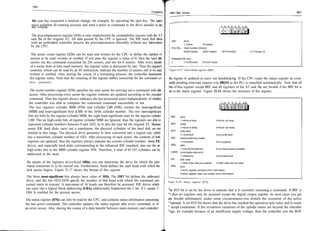
possible to connect a powerful optical drive by means of an IDE interface. Usually, one would Table 31.11: The AT task file
select an SCSI solution as this is more flexible In a number of ways than the AT bus.
One restriction of IDE Is the maximum cable length of 187/ (46 cm); some manufacturers also
allow up to 247/ (61 cm). For larger systems which occupy several cabinets, this Is too little, but 7 6 5 4 3 2 1 0
JABT
|NTO
O Q
BBK
for a personal computer even In a large tower case It is sufficient. These values are part of the Z
IDE standard. Thus, it is not Impossible that the cables may be longer; but the IDE standard
does not guarantee this. BBK: 1 =sector marked as bad by host 0=no error
UNC: 1 =uncorrectable data error 0=no or correctable data error
NID: 1=ID mark not found 0=no error
The AT File ABT: command abort
1 =command aborted 0=command executed
NTO: 1 =track 0 not found 0=no error
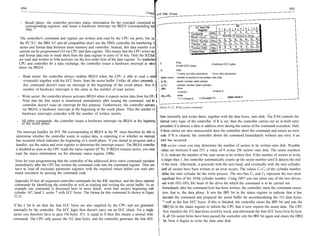
The CPU accesses the controller of the IDE hard disk by means of several data and control HUM: 1 =data address mark not found 0=no error
registers, commonly called the AT task file. The address and assignment of these registers is x: unused
identical to that of the hard disk controller with an ST506 interface In the IBM AT, but note that
the registers are not compatible with the XT task file, or other Interfaces such as ESDI or SCSI. Enhanced IDE only:
0=medium not changed
The AT task file is divided into two register groups with port base addresses ifOh and 3f0h. The MC: 1=medium changed
MCR: 1 =medium change required 0=no medium change required
following sections describe the registers of the AT task file and their meaning in more detail
Table 81.11 lists all the registers concerned.
Figure 31.16: Error register (Iflh).
The data register, which Is the only 16-bit register of the AT task file, can be read or written by
the CPU to transfer data between main memory and the controller. The original AT interface A set NDM bit indicates that the controller hasn't found a data address mark on the data carrier.
supported only programmed Input/output via registers and ports, but no data transfer by If NTO is set this means that after a corresponding command the drive was unable to position
means of DMA. The reading and writing Is carried out In units of 16 bits; only the ECC bytes the read/write head above track 0. If the controller had to abort execution of the active com-
during the course of a read-long command are passed byte by byte. In this case, you must use mand because of an error, the ABT bit is set. If the MD bit is equal to 1 the c o n t r o l wa
the low-order byte of the register. Note that the data in the data register is only valid if the DRQ unable to detect the ID address mark concerned on the data carrier. A set UNC bit shows that
bit In the status register Is set.
an uncorrectable data error has occurred; the data is invalid even after applying the ECC code^
If BBK is equal to 1 then the CPU has earlier marked the sector concerned as bad; it can no
The CPU can only read the error register; It contains error information concerning the last active longer be accessed.
command If the ERR bit In the status register Is set and the BSY bit In the status register Is
cleared; otherwise, the entries In the error register are not defined. Note that the meaning of this For supporting drives with removable volumes, enhanced IDE implements the (formerly
register differs for the diagnostics command. Figure 31.16 shows the structure of the error register. reserved) MC and MCR bits. A set MC bit indicates that the volume in the, dnve has been
changed, thus it corresponds to the disk change bit of the floppies. A set MCR bit shows that](https://image.slidesharecdn.com/ide-100104082519-phpapp01/85/Ide-4-320.jpg)
![896
897
Chapter. Hard Disk Drives
If the first sector has been written then the controller Issues an interrupt 76h via IRQ14. int_count++;
handler concerned now transfers the 516 bytes of the following sector data via the data registerJ
if (int_CQunt<4) { /* ignore interrupt at the beginning of result phase*/
to the controller in the same manner as described above. This process is repeated four timej
for (word__count = 0; word_count < 256; word_count++, word_pointer++) {
until all four sectors, together with their ECC bytes, have been written. | outpw(0xlf0# *word_pointer); /* transfer 256 words = 512 data bytes */
Example: Write four sectors starting with, cylinder 167^ head 3^ sector 7 together with E C I
C }
bytes onto master drive (languages Microsoft C 5.10). | for (byte_count = 0; byte_count < 4; byte_count++, byte_pointer++) {
outp(0xlf0# *byte__pointer); /* transfer 4 ECC bytes */
i
unsigned int word_buffer [1024]; |
unsigned char byte_buffer [16]; § return;
unsigned int *word_pointer; | }
unsigned char *byte_pointer; !
int int_count; |
In the example,
the handler for IRQ14 serves only for transferring the data; a more extensive
main () j function, for example for determining the interrupt source, is not implemented. The 2048 data
l;
{ int word_count^ byte_count; bytes in 1024 data words as well as the 16 ECC bytes must be suitably initialized. This is not
void far ^old_irql4;
word_pointer = &word_buf f er; /* initialize */ carried out here because of the lack of space. Furthermore, the procedure status_check() for
byte_pointer = &byte_bu£fer; /* pointer */ checking the status information is not listed in detail
init_buffers();
/* initialize buffer */
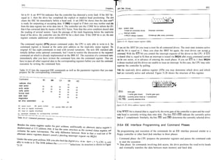
old_irql4 = _dos_getvect(0x76); Upon the last interrupt the result phase is entered. Figure 31.22 shows the task file registers that
/* set new interrupt */ contain valid status information after the command has been completed. The entries in the error
_dos_setvect (0x7 6, new_irgl4());
/* for IRQ14 */
while((inp(0xlf7) & 0x80) == 0x80);
register are only valid if the ERR bit in the status register is set and the BSY bit is cleared.
outp(0xlf2, 0x04); /* wait until BSY in status register is cleared */
©utp(0xl£3, 0x07); /* register sector counti 4 sectors */
outp(0x1f4, 0xa7); /* register sector number: 7 */ AT Task File Bit I
Registe 7 | 6 I 5 4 | 3 2 1 u
outp(0xl£5, 0x00); /* register cylinder LSBs 167 */
NDM NTO ABT x NID x UNCBBK 1
outp(Qxl£6^ 0xa3);
outp(0xlf7, 0x33);
/* register cylinder MSB? 0 */
/* register drive/head: DRV=0y head-3 */
/* register commands opcodesOOHOO^ Lsl, R=l */
Error (ifih)
Sector Count (1f2h)
Sector Number (1f3h)
Number of Sectors Written
S7 S6 S5 S4 S3 S 2 Si So
1
1
Cylinder LSB (1f4h) C7 C6 C5 C4 C3 C 2 C1 Co
/* write first sector (512 data bytes
+ 4 ECC bytes */
Cylinder MSB (1f5h) 0 0 0 0 0 0 C 9 c8 1
while ((inp(0xlf7) & 0x80) == 0x80 II
(inp(0xlf7) & 0x08) I =0x08); /* wait until BSY in Drive/Head (1f6h) 1 0 1 DRV HD3 HD2 HD1 HDo 1
status register is cleared and DRQ is set */ (1f7h) 1
BSY RDY WFT SKC DRQ COR IDX ERR
word_pointer = word_buf f er;
for (word_count = 0; word_count < 256; /* initialize pointer */
Status
1
outpw(0xlf0^ *word_pointer); word_count++, word_pointer+ +) {
} /* transfer 256 words = 512 data bytes */ NDM: 1 =data address mark not found 0=no error
NTO: 1=trackO not found 0=no error
byte_pointer = byte_buf f er; ABT: instruction abort
/* initialize pointer */ O=instruction executed
for (byte_count = 0; byte_count < 4; 1 instruction aborted
byte_count+ + ^ byte_pointer-f + ) {
outp(0xlf0, *byte_pointer); NID: 1=ID mark not found 0=no error
} /* transfer 4 ECC bytes */ 0=no or correctable data error
UNC: 1 =not-correctable data error
BBK: 1 =sector marked bad by host 0=no error
int_count=0;
/* initialize interrupt count */ DRV: drive
while (int__count < 4 ) ; 1 =slave 0=master
/* wait until all four sectors are transferred */ C9-C0, S 7 -S 0 , HD 3 -HD 0 : sector identification of last written sector
_dos_setvect(0x7 6, old_irql4());
/* set old IRQ14 #/
status_check();
/* check status information and determine error %wre 32.22: Result phase of «Write Sector» instruction.
code */
exit(0);
} According to the sector Identification, you can determine the last written sector or the sector
w
Mch gave rise to the command abortion. The sector count register specifies the number of
void interrupt far new_irql4()
{ int word_count# byte_count;
sectors still to be written, that is, a value of 0 If the command has been terminated without any
error.](https://image.slidesharecdn.com/ide-100104082519-phpapp01/85/Ide-8-320.jpg)