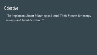
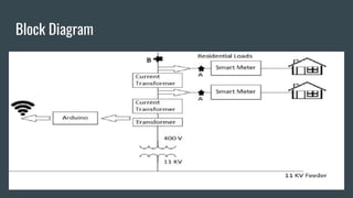
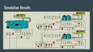
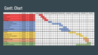
IoT based Smart Grid
Group 10
Ayesha Nishwa 2017091
Minahill Jamshaid 2017202
M. Rohan Saeed 2017307
M. Saim Siddiqui 2017311
Advisor: Dr. Ammar Arshad
Co-Advisor: Dr. Shahid Alam
Objective
“To implement Smart Metering and Anti-Theft System for energy
savings and fraud detection.”
Block Diagram
B
Analysis And Design
Software Design and Simulation
Circuit Diagram:
Software Design and Simulation(Cont.)
● Proteus is used for the software designing of the smart grid
● Circuit diagram divided into two parts: Smart energy meter and theft detection
● A smart meter is divided into two modules transmission unit and receiver unit
● There are two smart meters that displays units consumed and calculates bill.
● For theft detection data was used and compared to check any unit difference.
● The Arduino UNO and Arduino Mega was coded in order to interface smart
metering and theft detection
Coding Flowchart(s)
Coding Flowchart(s) (cont.)
Simulation Results
Communication
The communication is divided into four parts:
 Communication between two Bluetooth modules:
○ Master and Slave concept in AT mode
○ Programmed to connect to the same module every time
○ Smooth transfer of values from Arduino UNO to Arduino Mega
 Communication between Bluetooth module and Arduino:
○ HC-05 Bluetooth module is connected with Arduino in Full Duple Scheme.
○ The data is received, forwarded to Arduino and stored for later use.
Communication (contd.)
 Communication between Arduino and NodeMCU:
○ Arduino and NodeMCU connected in Full Duplex Connection Scheme.
○ All data values were sent to NodeMCU serially.
 Communication between NodeMCU and Mobile Application:
o Developing a mobile application that is compatible with Android operating system.
o Displaying of data
Displaying Results
● Displaying Meter reading of two smart
meters at houses and at service main on
mobile App.
● Displaying theft detection of meter 2 and at
service main on mobile App.
Hardware Design (PCB)
● Easy-PC Software.
● Single sided PCB was designed.
● Dimensions of smart meter are 7” wide and 9.7” long.
● Total PCBs designed were three.
● Vero board was used.
Hardware Design (PCB) (cont.)
Hardware Implementation
Individual Contribution
➢ Ayesha Nishwa and Minahill Jamshaid
1. PCB Design.
➢ Muhammad Rohan Saeed and Muhammad Saim Siddiqui
1. Assembling and Soldering of Components on PCB.
➢ Collaborative Efforts
1. Serial Communication between Meter(s) and Grid.
2. Interfacing Smart Meter with Anti-Theft System.
3. Writing Parts of Code.
4. App development.
5. Troubleshooting.
Progress in H/W and S/W
● Software:
➢ Completed:
1. Smart Meter Simulation
2. Stabilization of current and voltage values.
3. Calculation and Billing of units.
4. Theft Detection using Comparison between two values.
Progress in H/W and S/W (cont.)
● Hardware:
➢ Completed:
1. PCB Design.
2. Assembling and Implementation of Components. :
3. Communication.
Gantt. Chart
Thank You!

IoT based smart grid FYP for students

  • 1.
    IoT based SmartGrid Group 10 Ayesha Nishwa 2017091 Minahill Jamshaid 2017202 M. Rohan Saeed 2017307 M. Saim Siddiqui 2017311 Advisor: Dr. Ammar Arshad Co-Advisor: Dr. Shahid Alam
  • 2.
    Objective “To implement SmartMetering and Anti-Theft System for energy savings and fraud detection.”
  • 3.
  • 4.
  • 5.
    Software Design andSimulation Circuit Diagram:
  • 6.
    Software Design andSimulation(Cont.) ● Proteus is used for the software designing of the smart grid ● Circuit diagram divided into two parts: Smart energy meter and theft detection ● A smart meter is divided into two modules transmission unit and receiver unit ● There are two smart meters that displays units consumed and calculates bill. ● For theft detection data was used and compared to check any unit difference. ● The Arduino UNO and Arduino Mega was coded in order to interface smart metering and theft detection
  • 7.
  • 8.
  • 9.
  • 10.
    Communication The communication isdivided into four parts:  Communication between two Bluetooth modules: ○ Master and Slave concept in AT mode ○ Programmed to connect to the same module every time ○ Smooth transfer of values from Arduino UNO to Arduino Mega  Communication between Bluetooth module and Arduino: ○ HC-05 Bluetooth module is connected with Arduino in Full Duple Scheme. ○ The data is received, forwarded to Arduino and stored for later use.
  • 11.
    Communication (contd.)  Communicationbetween Arduino and NodeMCU: ○ Arduino and NodeMCU connected in Full Duplex Connection Scheme. ○ All data values were sent to NodeMCU serially.  Communication between NodeMCU and Mobile Application: o Developing a mobile application that is compatible with Android operating system. o Displaying of data
  • 12.
    Displaying Results ● DisplayingMeter reading of two smart meters at houses and at service main on mobile App. ● Displaying theft detection of meter 2 and at service main on mobile App.
  • 13.
    Hardware Design (PCB) ●Easy-PC Software. ● Single sided PCB was designed. ● Dimensions of smart meter are 7” wide and 9.7” long. ● Total PCBs designed were three. ● Vero board was used.
  • 14.
  • 15.
  • 16.
    Individual Contribution ➢ AyeshaNishwa and Minahill Jamshaid 1. PCB Design. ➢ Muhammad Rohan Saeed and Muhammad Saim Siddiqui 1. Assembling and Soldering of Components on PCB. ➢ Collaborative Efforts 1. Serial Communication between Meter(s) and Grid. 2. Interfacing Smart Meter with Anti-Theft System. 3. Writing Parts of Code. 4. App development. 5. Troubleshooting.
  • 17.
    Progress in H/Wand S/W ● Software: ➢ Completed: 1. Smart Meter Simulation 2. Stabilization of current and voltage values. 3. Calculation and Billing of units. 4. Theft Detection using Comparison between two values.
  • 18.
    Progress in H/Wand S/W (cont.) ● Hardware: ➢ Completed: 1. PCB Design. 2. Assembling and Implementation of Components. : 3. Communication.
  • 19.
  • 20.