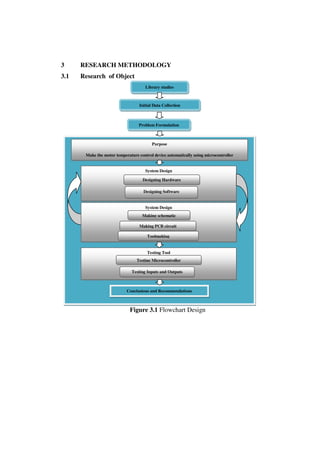
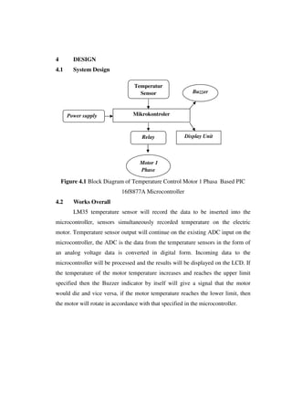
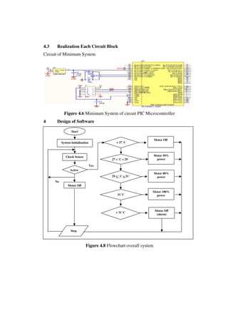
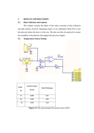
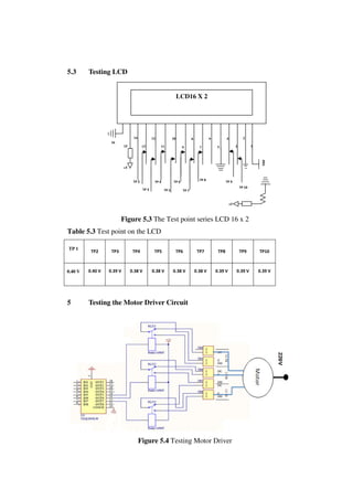
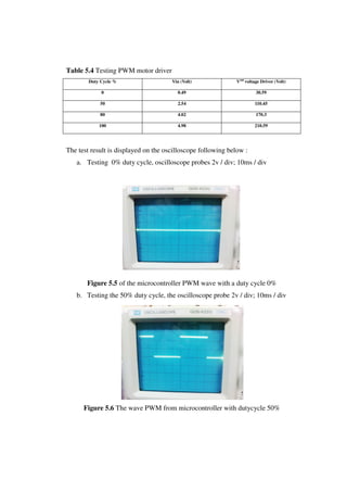
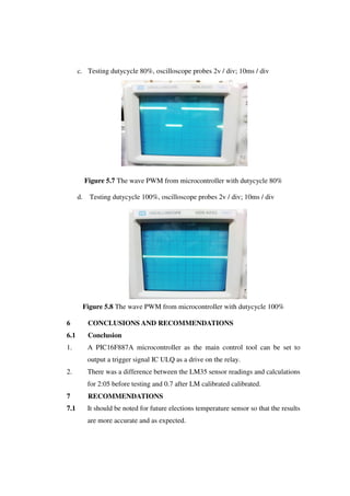
This document describes the design of a temperature control system for a single-phase motor using a PIC16f887A microcontroller. The system uses an LM35 temperature sensor to monitor the motor temperature and sends the data to the microcontroller. If the temperature reaches the upper limit, a buzzer will sound as a warning. The microcontroller can control the motor speed based on the temperature. Experimental results show the microcontroller can accurately adjust the motor speed according to temperature changes.
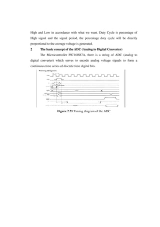
DESIGN AND DEVELOPMENT OF A LOW-COST MICROCONTROLLER BASED SINGLE PHASE WATER...ijistjournal
This document describes the design and development of a low-cost microcontroller based single phase water-pump controller. The system uses a PIC12F675 microcontroller to monitor current from a current sensor and control a relay based on the sensed current level. It was developed as an improved alternative to previous transistor-based designs. The system provides over-current and over-voltage protection for water pumps. Testing showed the microcontroller-based design has higher accuracy, faster operation speed, and simpler circuitry compared to previous approaches. It provides effective and low-cost protection of water pumps from power fluctuations.
Temperature Based Fan Controller can be used for reducing the power consumption & also to assist people who are disabled and are unable to control the speed of fan.It may also be used for monitoring changes in environment.
This paper presents an innovative prototype design of electric fan with smart characteristics. This electric fan uses a microcontroller to produce an automation function. It also has a unique double feature designs, such as using 2 fans, 2 Light Emitting Diodes (LED) and 2 sensors. This is to ensure the cooling process operates more efficiently and effectively, especially for a large space application and in hot weather due to global warming. By applying the circuit, it offers a better life for human. It is really practical for senior citizens to make their life simpler. The circuit is also suitable for disabled people who have difficulty to switch on the fan manually. Lastly, the circuit can be manipulated by diversifying its function as a detector, where it can produce an alarm signal when emergency case occurs such as the house or premise is on fire.
temperature dependent dc fan speed controller withou using micrcontrollerDeepak Yadav
This document describes the development of an automatic fan system that controls fan speed based on room temperature. It uses a LM35 temperature sensor to detect temperature changes and an LM3914 integrated circuit to automatically adjust the fan speed through relays. The system aims to enable automatic fan speed control, develop an automatic fan system that changes speed according to temperature, and allow users to view the temperature and speed status on an LCD display. It works by sensing temperature with the LM35 sensor and sending the output to the LM3914 IC, which activates relays to change the fan speed as the temperature rises or falls.
This document presents a mini project on an automatic temperature controlled fan. It includes an introduction, block diagram, components used, power supply details, and an introduction to the microcontroller used - PIC16F72. The system uses an LM35 temperature sensor, PIC microcontroller, DC fan driver circuit, resistors, diodes, capacitors, and voltage regulator. It regulates fan speed automatically based on temperature readings from the LM35 sensor through PWM control of the fan's driver circuit.
This document describes an RF-based transformer temperature monitoring system. The system uses a temperature sensor interfaced with a microcontroller to monitor and display the temperature on an LCD. The temperature is also transmitted via RF to a remote receiver connected to a PC. Key components include a temperature sensor, microcontroller, LCD, RF transmitter and receiver modules. The system is designed and programmed to continuously monitor and log transformer temperature remotely.
This document describes a temperature controlled fan project. It contains a block diagram showing the main components: an 8051 microcontroller, temperature sensor, ADC, motor driver, fan motor, and 7-segment displays. It also provides details on the working, which involves measuring temperature, displaying it on the 7-segment displays, and varying the fan speed based on the temperature using PWM. Simulation results and hardware implementation snapshots are included. The project aims to automatically control fan speed based on sensed temperature.
This project proposes automatic detection of human and energy saving room architecture to reduce standby power consumption and to make the temperature of the room easily controllable with an IR sensor and Lm35 temperature sensor using air conditioner . The proposed auto-detection of human done using the IR sensor to indicate the entering or exit ofthe persons. Microcontroller continuously monitors the infrared receiver. When any object pass throughthe IR receiver then the IR rays falling on the receiver are obstructed, this obstruction is sensed by the microcontroller ATMEGA16.When the temperature of the room is varied then the lm35 temperature sensor converts this temperature change into voltage which is then sensed by the microcontroller ATMEGA16 .
In such cases our project is aimed at starting one ac among both depending upon the temperature value at a particular room .If the temperature on the particular room is above certain range then the AC in that room will start up and during this time the AC in the other room will remain switched off. When the temperature goes below 25 degree in the room where AC is already on will be switched off automatically. Then if the temperature on the other room during the time is above 30degree then the AC in that room will start up and vice versa .The second feature of our project is aimed at switching of the AC automatically when there is absence of human beings in a particular room .The entire scheme is designed using number of ATMEGA16 microcontrollers , temperature sensors , digital counter ,IR sensors , relay etc.
This project will solve the day-to-day problem where AC’s do not start up due to low voltage generally in rural areas .This will start the AC depending upon the temperature label in a room by sharing the load .Also this project can be extended for controlling the temperature in more rooms in an apartment.
This document describes two devices for measuring water levels in dug wells: a mechanical device and an ultrasonic (SONAR) device.
The mechanical device uses a float attached to the device by a wire to measure depth. As the float sinks and the wire plays out, a sensor counts rotations of a pulley to calculate depth. When the float touches water, a circuit is completed to signal the reading.
The SONAR device uses an ultrasonic sensor to measure distance to the water surface by emitting a pulse and measuring the echo return time. The sensor's range is increased using a parabolic reflector to concentrate the acoustic beam. Both devices aim to be low-cost, portable, and battery-powered for
The document outlines the design, construction, and testing of an automatic speed controller for a fan based on temperature readings from a sensor. Key points:
- The controller automatically adjusts the fan speed based on the temperature detected by a sensor to conserve energy and provide user convenience.
- It uses an Arduino board to control the speed of a DC motor connected to the fan via pulse width modulation based on temperature readings from a DHT11 sensor.
- The controller was tested over a temperature range of 30-34°C and showed that it successfully increased or decreased the fan speed from 2550-4910 rpm as the temperature increased or decreased respectively, with errors within 4%.
Automatic room temperature controlled fan using arduino uno microcontrollerMohammod Al Emran
This paper presents the designs and the simulation of a DC fan control system based on room temperature using pulse width modulation technique, humidity and temperature sensor namely DHT11 with Arduino Uno Microcontroller. The fan will be used to reduce temperature of a room at certain level. To build the fan, we will use DTH11 Humidity Sensor. The sensor will measure the temperature continuously. When the temperature gets higher from a specific temperature, the fan will be on “On” mode. The speed of the fan will be determined by pwm using pulse-width modulation. The temperature along with the speed of the fan will be displayed through LCD monitor.
Here is a circuit through which the
speed of a fan can be linearly controlled
automatically, depending
on the room temperature. The circuit is
highly efficient as it uses thyristors for
power control. Alternatively, the same
circuit can be used for automatic temperature
controlled AC power control.
In this circuit, the temperature sensor
used is an NTC thermistor, i.e. one having
a negative temperature coefficient. The
value of thermistor resistance at 25°C is
about 1 kilo-ohm.
Op-amp A1 essentially works as
I to V (current-to-voltage) converter
and converts temperature variations
into voltage variations. To amplify
the change in voltage due to change in
temperature, instrumentation amplifier
formed by op-amps A2, A3 and A4
is used. Resistor R2 and zener diode
D1 combination is used for generating
reference voltage as we want to amplify
only change in voltage due to the
change in temperature.
Op-amp μA741 (IC2) works as a
comparator. One input to the comparator
is the output from the instrumentation
amplifier while the other input
is the stepped down, rectified and
suitably attenuated sample of AC voltage.
This is a negative going pulsating
DC voltage. It will be observed that
with increase in temperature, pin 2 of
IC2 goes more and more negative and
hence the width of the positive going
output pulses (at pin 6) increases linearly
with the temperature. Thus IC2
functions as a pulse width modulator
in this circuit. The output from the
comparator is coupled to an optocoupler,
which in turn controls the AC
power delivered to fan (load).
The circuit has a high sensitivity and
the output RMS voltage (across load) can
be varied from 120V to 230V (for a temp.
range of 22°C to 36°C), and hence wide
variations in speed are available. Also
note that speed varies linearly and not
in steps. Besides, since an optocoupler is
used, the control circuit is fully isolated
from power circuit, thus providing added
safety. Note that for any given temperature
the speed of fan (i.e. voltage across
load) can be adjusted to a desired value
by adjusting potmeters VR1 and VR2
appropriately.
Potmeter VR1 should he initially kept
in its mid position to realise a gain of approximately
40 from the instrumentation
amplifier. It may be subsequently trimmed
slightly to obtain linear variation of the
fan speed.
A project report on Remote Monitoring of a Power Station using GSM and ArduinoJawwad Sadiq Ayon
This document describes a project to remotely monitor the voltage of a power station/substation using GSM. An Arduino board measures the voltage using a potential divider circuit and sends the readings via a SIM908 GSM module in SMS messages. The project prototype monitors voltage, displays it on an LCD, and sends updates every 10 minutes. Future work could expand monitoring to other parameters and use GPRS for remote access from anywhere via the internet.
Temperature based fan speed control & monitoring usingJagannath Dutta
Our object of making this project is for reducing the power consumption. And also to assist people who are disabled and are unable to control the speed of fan.
Final Year Project Report on Dual Channel Home Appliance ControlEkram Bin Mamun
In the current revolution of digital world, people like convenience in using technology to make their life more easy and comfortable. People feels to control their home appliances like light, fan etc. in more convenient way rather than by switch board as they need walking across the room to either on or off such appliances. The varying line voltages due to use of backup power like IPS or generator and sudden change of weather at night during our sleep results cold related diseases like coughing and fever from high speed of fan. These cold related diseases due to these situations are very common for babies and old people. This project will remove these problems by giving constant fan speed even if the line voltage varies and by changing the fan speed with the change of ambient temperature. This system also has additional features like two different set of remote control system (IR and Bluetooth) embedded together and a 16x2 LCD display which shows various information like output voltage and room temperature.
International Journal of Engineering Research and Applications (IJERA) is an open access online peer reviewed international journal that publishes research and review articles in the fields of Computer Science, Neural Networks, Electrical Engineering, Software Engineering, Information Technology, Mechanical Engineering, Chemical Engineering, Plastic Engineering, Food Technology, Textile Engineering, Nano Technology & science, Power Electronics, Electronics & Communication Engineering, Computational mathematics, Image processing, Civil Engineering, Structural Engineering, Environmental Engineering, VLSI Testing & Low Power VLSI Design etc.
This document describes an automatic temperature-controlled fan project using an Arduino Uno microcontroller. The fan will automatically turn on when the temperature reaches 35°C as measured by a temperature sensor, and will turn off again when the temperature drops below 35°C, in order to regulate the environment and reduce energy consumption. The system includes an Arduino, temperature sensor, LCD display, DC motor fan, battery power source, and connecting wires. Potential applications include use in homes and industries to assist people and save electricity by automating fan control based on temperature changes.
This 3-page lab report describes a temperature controlled automatic switch circuit project. The circuit uses an LM35 temperature sensor and LM358 op-amp to monitor temperature. When temperature exceeds 30 degrees Celsius, the op-amp triggers a transistor to power a relay, switching on a connected appliance like a light bulb or fan. The threshold can be adjusted using a variable resistor. The circuit provides automatic temperature-based control of home appliances without manual intervention.
speed control of three phase induction motor using IOTswaroop009
This project controls and monitors the speed of a three-phase induction motor using an Arduino and Node MCU controller. The Arduino implements PWM to control the motor speed using a three-phase driver circuit. Node MCU is used to increase and decrease the speed and establishes feedback of the speed to the Node MCU, which transmits the signal over Wi-Fi. This allows remote control of the motor speed through an IP address. The hardware components include a power supply, transformer, rectifier, inverter, driver circuit, Node MCU, Arduino and connecting wires. MATLAB is used to simulate the three-phase inverter and hardware results are obtained.
final Year Projects, Final Year Projects in Chennai, Software Projects, Embedded Projects, Microcontrollers Projects, DSP Projects, VLSI Projects, Matlab Projects, Java Projects, .NET Projects, IEEE Projects, IEEE 2009 Projects, IEEE 2009 Projects, Software, IEEE 2009 Projects, Embedded, Software IEEE 2009 Projects, Embedded IEEE 2009 Projects, Final Year Project Titles, Final Year Project Reports, Final Year Project Review, Robotics Projects, Mechanical Projects, Electrical Projects, Power Electronics Projects, Power System Projects, Model Projects, Java Projects, J2EE Projects, Engineering Projects, Student Projects, Engineering College Projects, MCA Projects, BE Projects, BTech Projects, ME Projects, MTech Projects, Wireless Networks Projects, Network Security Projects, Networking Projects, final year projects, ieee projects, student projects, college projects, ieee projects in chennai, java projects, software ieee projects, embedded ieee projects, "ieee2009projects", "final year projects", "ieee projects", "Engineering Projects", "Final Year Projects in Chennai", "Final year Projects at Chennai", Java Projects, ASP.NET Projects, VB.NET Projects, C# Projects, Visual C++ Projects, Matlab Projects, NS2 Projects, C Projects, Microcontroller Projects, ATMEL Projects, PIC Projects, ARM Projects, DSP Projects, VLSI Projects, FPGA Projects, CPLD Projects, Power Electronics Projects, Electrical Projects, Robotics Projects, Solor Projects, MEMS Projects, J2EE Projects, J2ME Projects, AJAX Projects, Structs Projects, EJB Projects, Real Time Projects, Live Projects, Student Projects, Engineering Projects, MCA Projects, MBA Projects, College Projects, BE Projects, BTech Projects, ME Projects, MTech Projects, M.Sc Projects, Final Year Java Projects, Final Year ASP.NET Projects, Final Year VB.NET Projects, Final Year C# Projects, Final Year Visual C++ Projects, Final Year Matlab Projects, Final Year NS2 Projects, Final Year C Projects, Final Year Microcontroller Projects, Final Year ATMEL Projects, Final Year PIC Projects, Final Year ARM Projects, Final Year DSP Projects, Final Year VLSI Projects, Final Year FPGA Projects, Final Year CPLD Projects, Final Year Power Electronics Projects, Final Year Electrical Projects, Final Year Robotics Projects, Final Year Solor Projects, Final Year MEMS Projects, Final Year J2EE Projects, Final Year J2ME Projects, Final Year AJAX Projects, Final Year Structs Projects, Final Year EJB Projects, Final Year Real Time Projects, Final Year Live Projects, Final Year Student Projects, Final Year Engineering Projects, Final Year MCA Projects, Final Year MBA Projects, Final Year College Projects, Final Year BE Projects, Final Year BTech Projects, Final Year ME Projects, Final Year MTech Projects, Final Year M.Sc Projects, IEEE Java Projects, ASP.NET Projects, VB.NET Projects, C# Projects, Visual C++ Projects, Matlab Projects, NS2 Projects, C Projects, Microcontroller Projects, ATMEL Projects, PIC Projects, ARM Projects, DSP Projects, VLSI Projects, FPGA Projects, CPLD Projects, Power Electronics Projects, Electrical Projects, Robotics Projects, Solor Projects, MEMS Projects, J2EE Projects, J2ME Projects, AJAX Projects, Structs Projects, EJB Projects, Real Time Projects, Live Projects, Student Projects, Engineering Projects, MCA Projects, MBA Projects, College Projects, BE Projects, BTech Projects, ME Projects, MTech Projects, M.Sc Projects, IEEE 2009 Java Projects, IEEE 2009 ASP.NET Projects, IEEE 2009 VB.NET Projects, IEEE 2009 C# Projects, IEEE 2009 Visual C++ Projects, IEEE 2009 Matlab Projects, IEEE 2009 NS2 Projects, IEEE 2009 C Projects, IEEE 2009 Microcontroller Projects, IEEE 2009 ATMEL Projects, IEEE 2009 PIC Projects, IEEE 2009 ARM Projects, IEEE 2009 DSP Projects, IEEE 2009 VLSI Projects, IEEE 2009 FPGA Projects, IEEE 2009 CPLD Projects, IEEE 2009 Power Electronics Projects, IEEE 2009 Electrical Projects, IEEE 2009 Robotics Projects, IEEE 2009 Solor Projects, IEEE 2009 MEMS Projects, IEEE 2009 J2EE P
Arduino based automatic temperature controlled fan speed regulatorEdgefxkits & Solutions
Using an analog temperature LM35 interfaced to the built in ADC of a programmed Arduino to develop varying duty cycle of PWM output for a driver IC to run a DC motor automatically according to the sensed temperature at different speed based on the temperature sensed.
This document describes an industrial temperature controller that uses a microcontroller and digital temperature sensor to control the temperature of a device. It displays the current, minimum, and maximum temperatures on an LCD screen and uses a relay connected to a heating element to maintain the temperature within the set limits. The controller requires components like a transformer, voltage regulator, capacitors, resistors, and transistors. It is intended to control temperature in industrial applications like manufacturing to maintain quality.
This document describes a voltage controlled digital AC dimmer project created by four students. The circuit uses a bridge rectifier, 4N25 optocoupler, microcontroller, MOC3021 TRIAC driver, and BT136 TRIAC to control the brightness of an LED by digitally controlling the firing angle of the TRIAC. Waveforms are shown for three different firing angle readings, and efforts taken to build the circuit as well as expenses are documented.
Monitoring and Controlling of BLDC motor using IOTvivatechijri
Brushless Direct Current motors are synchronous motors which operates on DC current. These motors have various advantages over Brushed DC motors such as low cost, high speed torque characteristics, noise less operation. Speed controlling is Very important. Speed of the motor is controlled by (ESC) electronic speed controlled. The parameters like Speed, Current, Power, Temperature and Voltage are Monitored on from remote access through the configured electronic gadgets by using the Internet Of things. the purpose of this project is to control and monitor the of Brushless DC (BLDC) motor by using IOT. The Internet of Things (IOT) has led to huge development in digital world. IOT is interface that helps communication between objects Brushless DC Motor (BLDCM) has various features like high efficiency, reliability, high weight to torque ratio. Hence these motors have major significances in the industries. By utilizing this IOT, controlling and monitoring of a system is done to obtain desired output.
IRJET- Transformer Monitoring and Protection System using AVR Atmega16 Mi...IRJET Journal
This document describes the design and implementation of a RF-based distribution transformer monitoring system. The system monitors key parameters like load current, voltage, and oil temperature. Sensors collect this data which is sent via RF to a central monitoring station. Parameters are analyzed to identify potential failures from overloading or overheating. The system aims to program a microcontroller to continuously monitor a transformer and cut power via a relay if unsafe conditions are detected, to protect the transformer and power distribution system. It was implemented using an ATmega16 microcontroller, sensors, RF module, LCD display, and relay to automatically monitor and shut off a transformer if parameters exceed safe levels.
DESIGN OF TEMPERATURE BASED FAN SPEED CONTROL and MONITORING USING ARDUINORatnesh Kumar chaurasia
This practical temperature controller controls the temperature of any device according to its requirement for any industrial application, it also has a feature of remote speed control.
DESIGN AND DEVELOPMENT OF A LOW-COST MICROCONTROLLER BASED SINGLE PHASE WATER...ijistjournal
A microcontroller based advanced technique was designed and developed to protect the house hold appliances, such as water-pump from fluctuation of line voltage. This device was tested with upper and lower cutoff voltages set at ±10% of the normal supply voltage (220V, AC) and with an over-load current up to 10A. The current sensor’s output was monitored by the PIC12F675 microcontroller and used analog to digital protocol. A ‘C’ language program was developed to control the function of microcontroller, using PCWH compiler.
Design and simulation of Arduino Nano controlled DC-DC converters for low and...IJECEIAES
This document describes the design and simulation of Arduino Nano controlled DC-DC converters for low and medium power applications. It discusses how existing DC-DC converter controllers using PIC microcontrollers and op-amp circuits can be bulky and expensive. The document proposes using an Arduino Nano controller instead, which is small, low-cost, and efficient. It provides the circuit diagrams and design calculations for buck, boost, and buck-boost converter topologies. The operating principles and components are explained. Finally, the document simulates a buck converter circuit using the Arduino Nano controller in Proteus software to validate the output voltage waveform.
International Journal of Engineering Research and Development (IJERD)IJERD Editor
journal publishing, how to publish research paper, Call For research paper, international journal, publishing a paper, IJERD, journal of science and technology, how to get a research paper published, publishing a paper, publishing of journal, publishing of research paper, reserach and review articles, IJERD Journal, How to publish your research paper, publish research paper, open access engineering journal, Engineering journal, Mathemetics journal, Physics journal, Chemistry journal, Computer Engineering, Computer Science journal, how to submit your paper, peer reviw journal, indexed journal, reserach and review articles, engineering journal, www.ijerd.com, research journals,
yahoo journals, bing journals, International Journal of Engineering Research and Development, google journals, hard copy of journal
Implementation of an Improved Microcontroller Based Moving Message Display Sy...IOSR Journals
This document describes the implementation of an improved microcontroller-based moving message display system using a PIC16F648A microcontroller and a 49x8 LED dot matrix display. The microcontroller is programmed in assembly language to control the LED dot matrix and decade counters in a sequential manner to display a scrolling 23 character message. A limiting resistor is used for each output line from the microcontroller to the LEDs. The dynamic display scheme employed helps improve display brightness and reduce energy consumption by only lighting LEDs when being addressed rather than continuously.
This document describes the implementation of a microcontroller-based moving message display system using LEDs. A PIC16F648A microcontroller is programmed in assembly language to control a 49x8 LED dot matrix display and sequentially light the LEDs to display a 23 character message. Decade counters are used along with the microcontroller to produce the shifting action of the message. The circuit diagram and working principle are explained, including details of the microcontroller, power supply design, and component sizing calculations. The dynamic display scheme employed helps improve display brightness and reduce energy consumption.
Implementation of an Improved Microcontroller Based Moving Message Display Sy...IOSR Journals
This document describes the implementation of a microcontroller-based moving message display system using LEDs. A PIC16F648A microcontroller is programmed in assembly language to control a 49x8 LED dot matrix display and sequentially light the LEDs to display a 23 character message in a moving fashion. Decade counters are used along with the microcontroller to produce the shifting action of the characters. The dynamic display scheme employed helps improve display brightness and reduce energy consumption. Key components of the system include the microcontroller, counting unit with decade counters, LED display unit, and a power supply. PCB layout and programming of the microcontroller are discussed.
Implementation of an Improved Microcontroller Based Moving Message Display Sy...IOSR Journals
This document describes the implementation of a microcontroller-based moving message display system using LEDs. A PIC16F648A microcontroller is programmed in assembly language to control a 49x8 LED dot matrix display and sequentially light the LEDs to display a 23 character message. Decade counters are used along with the microcontroller to produce the shifting action of the message. The circuit diagram and working principle are explained, including details of the microcontroller, power supply design, and component sizing calculations. The dynamic display scheme employed helps improve display brightness and reduce energy consumption.
Implementation of an Improved Microcontroller Based Moving Message Display Sy...IOSR Journals
This document describes the implementation of a microcontroller-based moving message display system using LEDs. A PIC16F648A microcontroller is programmed in assembly language to control a 49x8 LED dot matrix display and sequentially light the LEDs to display a 23 character message. Decade counters are used along with the microcontroller to produce the shifting action of the message. The circuit diagram and working principle are explained, including details of the microcontroller, power supply design, and sizing calculations for the transformer and filter capacitor. The dynamic display scheme employed helps improve display brightness and reduce energy consumption.
Digital Current Mode Controller for Buck ConverterIJMREMJournal
Power electronics applications are widely used in different fields of engineering like computer,
Telecommunication, electrical power and Mechanical), one of the most useful power electronics converters is
DC-DC buck converter. Owing to its numerous applications, its performance needs to be improved through a
suitable controller. In this Paper, A digital current mode controller is proposed and implemented for Buck
converter. Proposed current mode control technique is simulated in MATLAB/SIMULINK and results are
validated through hardware implementation. Both simulation and experimental analysis show effectiveness of
the proposed controller.
Design of embedded based three phase preventor and selector system for indust...IAEME Publication
This document summarizes a research paper that presents the design of an embedded-based three-phase preventor and selector system for industrial appliances. The system uses a microcontroller to control MOSFET-based inverters and provide safety operations for industry applications. It protects appliances from damage if one phase fails by using the power from another available phase. The system includes components like a DIP switch, microcontroller, signal amplifier, inverter circuitry, opto-isolator, gate drive power supply and MOSFET-based inverter to selectively provide power from one of three phases to industrial equipment.
The document describes the design of a 5V regulated power supply circuit using a voltage regulator integrated circuit. It provides background on the need for regulated power supplies in electronics and describes the workings of fixed voltage regulator ICs like the LM78XX series. It lists the input/output voltage ranges for common models and notes features like overcurrent protection, thermal shutdown and ease of use with few external components. The circuit aims to provide a stable 5V output for other parts of the hardware system from an unregulated DC source.
This document describes a minor project report submitted for a Bachelor of Technology degree in Electrical Engineering. It presents the design of a numeric water level indicator system. The system uses various electronic components like metallic contacts, a transformer, full-wave rectifier, IC chips 74HC147 and CD4511, a seven segment display, transistors, and LEDs. Diagrams of the circuit and its logic operation are provided. The report also includes an introduction, objectives, organization of the project, descriptions of the main components, circuit diagrams, the basic logic and operation, advantages, cost estimation, results, conclusions, and future work.
DC MOTOR SPEED CONTROL USING ON-OFF CONTROLLER BY PIC16F877A MICROCONTROLLERTridib Bose
This presentation consists the speed control of a dc motor using hardware (microcontroller) by changing the reference voltages logically and minimising errors.
This document outlines a project to build a sound-activated message display using a PIC microcontroller and LCD screen. Chapter 1 introduces the project, which will show a message on the LCD when sound is detected. Chapter 2 provides more details on the circuit design, including a microphone sound sensor, amplifier, control circuit, and LCD display module. It also includes a block diagram of the overall system. Subsequent chapters will discuss the methodology, testing process, future applications, and conclusions from the project.
Real time parameter estimation for power quality control and intelligent prot...EG TECHNOLOGIES
The document describes a method for real-time parameter estimation of power system impedance using signals from grid-connected power electronic converters. The proposed impedance estimation technique uses wavelets to analyze voltage and current transients from small disturbances imposed by power converters to determine the net impedance back to the power source. This allows for accurate impedance estimation within 5 milliseconds, providing the potential for fault detection within half a power cycle. The technique could enhance distributed generation operation during faults.
Project report on the Digital clock using RTC and microcontroller 8051Maulik Sanchela
1. The document describes a project report for a digital clock circuit with time and alarm functions. The circuit uses an RTC chip to accurately display the time and date. It can set the time and alarm and displays it on an LCD.
2. The circuit diagram shows how the RTC connects to the microcontroller and how it continuously reads the RTC data and processes it to display the correct time on the LCD. It uses buttons to set the time and alarm.
3. The project aims to design an accurate digital clock with functions to set the time and alarm using common electronic components like a microcontroller, RTC, LCD, and buttons.
The aim of this paper is to control the speed of DC motor. The main advantage in using a DC
motor is that the Speed-Torque relationship can be varied to almost any useful form. To achieve the
speed control an electronic technique called Pulse Width Modulation is used which generates High and
Low pulses. These pulses vary the speed in the motor. For the generation of these pulses a
microcontroller (AT89c51) is used. As a microcontroller is used to set the speed ranges which is done by
changing the duty cycles time period in the program. This is practical and highly feasible in economic
point of view, and has an advantage of running motors of higher ratings. This paper gives a reliable,
durable, accurate and efficient way of speed control of a DC motor.
This document summarizes a project to control the speed of a DC motor using an ARM microcontroller. It describes the components used including the ARM microcontroller, motor driver, optocounter, and interfaces to an LCD display. It provides the schematic and code for the motor control system, which implements a PID control loop to control motor speed based on feedback from the optocounter. It also presents the final PCB design and hardware implementation of the DC motor speed control system using an ARM microcontroller.
This document presents the construction of a 2KVA inverter by six students at the Federal Polytechnic in Ede, Osun State, Nigeria. It was submitted in partial fulfillment of the requirements for an Ordinary National Diploma in Electrical Electronics Engineering. The document discusses the background, aims and objectives, literature review on early inverter designs, basic design considerations, and the difference between sine wave and modified sine wave inverters. The overall goal of the project was to efficiently convert DC power from a battery to high voltage AC power that can be used to power appliances.
Similar to DESIGN OF CONTROL TEMPERATURE MOTOR 1 PHASE WITH COMPATIBLE LOAD BASED PIC MICROCONTROLLER 16f887A (20)
Andreas Schleicher presents PISA 2022 Volume III - Creative Thinking - 18 Jun...EduSkills OECD
Andreas Schleicher, Director of Education and Skills at the OECD presents at the launch of PISA 2022 Volume III - Creative Minds, Creative Schools on 18 June 2024.
Gender and Mental Health - Counselling and Family Therapy Applications and In...PsychoTech Services
A proprietary approach developed by bringing together the best of learning theories from Psychology, design principles from the world of visualization, and pedagogical methods from over a decade of training experience, that enables you to: Learn better, faster!
This presentation was provided by Rebecca Benner, Ph.D., of the American Society of Anesthesiologists, for the second session of NISO's 2024 Training Series "DEIA in the Scholarly Landscape." Session Two: 'Expanding Pathways to Publishing Careers,' was held June 13, 2024.
Leveraging Generative AI to Drive Nonprofit InnovationTechSoup
In this webinar, participants learned how to utilize Generative AI to streamline operations and elevate member engagement. Amazon Web Service experts provided a customer specific use cases and dived into low/no-code tools that are quick and easy to deploy through Amazon Web Service (AWS.)
How Barcodes Can Be Leveraged Within Odoo 17Celine George
In this presentation, we will explore how barcodes can be leveraged within Odoo 17 to streamline our manufacturing processes. We will cover the configuration steps, how to utilize barcodes in different manufacturing scenarios, and the overall benefits of implementing this technology.
🔥🔥🔥🔥🔥🔥🔥🔥🔥
إضغ بين إيديكم من أقوى الملازم التي صممتها
ملزمة تشريح الجهاز الهيكلي (نظري 3)
💀💀💀💀💀💀💀💀💀💀
تتميز هذهِ الملزمة بعِدة مُميزات :
1- مُترجمة ترجمة تُناسب جميع المستويات
2- تحتوي على 78 رسم توضيحي لكل كلمة موجودة بالملزمة (لكل كلمة !!!!)
#فهم_ماكو_درخ
3- دقة الكتابة والصور عالية جداً جداً جداً
4- هُنالك بعض المعلومات تم توضيحها بشكل تفصيلي جداً (تُعتبر لدى الطالب أو الطالبة بإنها معلومات مُبهمة ومع ذلك تم توضيح هذهِ المعلومات المُبهمة بشكل تفصيلي جداً
5- الملزمة تشرح نفسها ب نفسها بس تكلك تعال اقراني
6- تحتوي الملزمة في اول سلايد على خارطة تتضمن جميع تفرُعات معلومات الجهاز الهيكلي المذكورة في هذهِ الملزمة
واخيراً هذهِ الملزمة حلالٌ عليكم وإتمنى منكم إن تدعولي بالخير والصحة والعافية فقط
كل التوفيق زملائي وزميلاتي ، زميلكم محمد الذهبي 💊💊
🔥🔥🔥🔥🔥🔥🔥🔥🔥
Level 3 NCEA - NZ: A Nation In the Making 1872 - 1900 SML.pptHenry Hollis
The History of NZ 1870-1900.
Making of a Nation.
From the NZ Wars to Liberals,
Richard Seddon, George Grey,
Social Laboratory, New Zealand,
Confiscations, Kotahitanga, Kingitanga, Parliament, Suffrage, Repudiation, Economic Change, Agriculture, Gold Mining, Timber, Flax, Sheep, Dairying,
Philippine Edukasyong Pantahanan at Pangkabuhayan (EPP) CurriculumMJDuyan
(𝐓𝐋𝐄 𝟏𝟎𝟎) (𝐋𝐞𝐬𝐬𝐨𝐧 𝟏)-𝐏𝐫𝐞𝐥𝐢𝐦𝐬
𝐃𝐢𝐬𝐜𝐮𝐬𝐬 𝐭𝐡𝐞 𝐄𝐏𝐏 𝐂𝐮𝐫𝐫𝐢𝐜𝐮𝐥𝐮𝐦 𝐢𝐧 𝐭𝐡𝐞 𝐏𝐡𝐢𝐥𝐢𝐩𝐩𝐢𝐧𝐞𝐬:
- Understand the goals and objectives of the Edukasyong Pantahanan at Pangkabuhayan (EPP) curriculum, recognizing its importance in fostering practical life skills and values among students. Students will also be able to identify the key components and subjects covered, such as agriculture, home economics, industrial arts, and information and communication technology.
𝐄𝐱𝐩𝐥𝐚𝐢𝐧 𝐭𝐡𝐞 𝐍𝐚𝐭𝐮𝐫𝐞 𝐚𝐧𝐝 𝐒𝐜𝐨𝐩𝐞 𝐨𝐟 𝐚𝐧 𝐄𝐧𝐭𝐫𝐞𝐩𝐫𝐞𝐧𝐞𝐮𝐫:
-Define entrepreneurship, distinguishing it from general business activities by emphasizing its focus on innovation, risk-taking, and value creation. Students will describe the characteristics and traits of successful entrepreneurs, including their roles and responsibilities, and discuss the broader economic and social impacts of entrepreneurial activities on both local and global scales.
Philippine Edukasyong Pantahanan at Pangkabuhayan (EPP) Curriculum
DESIGN OF CONTROL TEMPERATURE MOTOR 1 PHASE WITH COMPATIBLE LOAD BASED PIC MICROCONTROLLER 16f887A
1. JOURNAL
DESIGN OF CONTROL TEMPERATURE MOTOR 1
PHASE WITH COMPATIBLE LOAD BASED PIC
MICROCONTROLLER
16f887A
SUBMITTED BY :
Name : YUSMAN WESLEY R
NPM : 10.03.0.005
DEPARTMENT of ELECTRICAL ENGINEERING
FACULTY ENGINEERING
UNIVERSITY of RIAU ISLANDS
2014
2. DESIGN OF CONTROL TEMPERATURE MOTOR 1 PHASE
WITH COMPATIBLE LOAD BASED PIC
MICROCONTROLLER
16f887A
Yusman Wesley 1) , Pamor Gunoto 2), Anton Viantika 3)
Department of Electrical Engineering University of Riau Islands
ABSTRAK
The electric motor is widely used in electronic devices such as the fan,
computer, water pump and so forth. Existing properties on the electric motor
when the motor is rotating continuously, the temperature of the motor will also
increase. When the motor has reached a high temperature and the motor
continues to be used then the motor will be damaged, to the need for a
temperature control device on the electric motor microcontroller based on the
tool made.
LM35 temperature sensor will record the data to be inserted into the
microcontroller, sensors simultaneously recorded temperature on the electric
motor. Incoming data to the microcontroller will be processed and the results will
be displayed on the LCD. If the temperature of the motor temperature increases
and reaches the upper limit specified then the Buzzer indicator by itself will give a
signal that the motor would die.
From the discussion and analysis of the data obtained at the time of
measurement can be concluded that this PIC16f887A microcontroller can adjust
according to temperature changes in the motor 1 phase.
Keywords: Temperature, Microcontroller PIC16f887A, LM35, Motor AC.
1) Student Department of Electrical Engineering, Faculty Engineering, UNRIKA
BATAM.
2) Supervisor Department of Electrical Engineering, Faculty Engineering,
UNRIKA BATAM.
3) Co - Supervisor Department of Electrical Engineering, Faculty Engineering,
UNRIKA BATAM.
3. 1 INTRODUCTION
1.1 Background
Electric motors are often used in electronic devices such as the fan,
computer, water pump and so forth. Existing properties on the electric motor
when the motor is rotating continuously, the temperature of the motor will also
increase. When the motor has reached a high temperature and the motor continues
to be used then the motor will be damaged.
In larger-scale applications, so that the electric motor can operate longer
and can work effectively then change the motor temperature must be controlled.
Based on these considerations, the temperature control device made 1
phase motors and motor rotation speed with compatible PIC microcontroller-based
load 16f887A. This tool also controls the speed of the motor 1 phase when
the temperature increases on the motor then the motor will go down and vice
versa motor speed increases when the temperature of the motor is low. This tool
will be displayed on the temperature and the speed of the electric motor together
in one view.
1.2 Problem of Formulation
Creating a working tool that can automatically control the temperature
changes on the motor using PIC microcontroller technology 16f887A.
1.3 Research Objectives
1 Make gauges motor rotation speed and temperature of the PIC
microcontroller based 16f887A.
2 LCD display used
1.4 Scope of Problems
1 Explain the switching capabilities at the relay for the activation of the
motor along the motor temperature.
2 16f887A PIC microcontroller programming using C language.
4. 2 BASIC Of THEORY
2.1 Microcontroller PIC16f887A
Microcontroller is a microprocessor system in which there already are
CPU, RAM, ROM, I / O, CLOCK and other internal devices are already
connected and organized (address) with either by the manufacturer and is
packaged in a single chip that is ready to use. So we live program ROM contents
according to the rules of use by the factory that makes it.
Figure 2.1 Block Diagram PIC16f887A
5. 2.1.1 Configuration pin PIC16f887A
Figure 2.2 Pinout PIC16f887A
2.2 Basic of PIC16f887A Programming with C Language
The C language is a programming language that can be said to be different
between the low-level language (machine-oriented language), and high-level
language (the language of human-oriented). As is known, possessed a high level
language compatibility between platforms. Because it is very easy to program on
a variety of machines.
Maker of the C language is Brian W. and Dennis Kerninghan M.Ritcihe in
1972 C is a structured programming language, which divides the program in the
form of blocks. The goal is to facilitate the creation and development of the
program. The program is written in C easily transferred from one program to
another program language. This is due to the standardization of the C language in
the form of standard ANSI (American National Standards Institute) were used as a
reference by the compiler makers.
6. 2.3 Resistor
Resistors are electronic components poles designed to withstand electrical
current to produce an electric voltage between the two poles, the voltage value of
the resistance value is proportional to the current flowing, according to Ohm's
law:
V = I . R....................................................................................(2.1)
2.4 Capacitors
Capacitor in the electronic circuit denoted by the letter "C" is a device that
can store energy in the electric field or charge current, by collecting dati internal
imbalance of electric charge. Capacitors discovered by Michael Faraday (1791-
1867). Unit is Farad capacitor (F). One farad = 9 x 1011 cm2, which means the
large pieces.
2.5 LM35 (Temperature Sensor)
LM35 temperature sensor is an electronic component that has a function to
change the temperature scale into electrical quantities in the form of voltage.
LM35 has a high accuracy and ease of design compared with other temperature
sensor, LM35 also has a low output impedance and high linearity so it can be
easily connected with a series of special control and does not require further
adjustment.
Figure 2.10 Schematic temperature sensor circuit
7. 2.6 Crystals
Crystals are electronic components that use a mechanical resonance that
vibrates with piezoeelectric material to create an electrical signal with a very
precise frequency.
Figure 2.11 Crystals
2.7 Relay Drive
Relay is an electronic component in the form of an electronic switch
driven by electric current. In principle, the relay is a switch lever with the wire
windings on an iron rod (selenoid) nearby. When selenoid electrified, the lever
would be interested because of the presence of magnetic fields that occur in the
solenoid switch contacts will close. By the time the flow is stopped, the magnetic
force will be lost, the lever will return to its original position and will re-open
switch contacts. Relays are usually used to drive large currents or voltages, eg
electrical equipment 4 Ampere 220 Volt AC, using a small current or voltage,
such as 0.1 Ampere 220 Volt DC. The simplest relay is an electromechanical
relays which provide the mechanical movement of getting electrical energy.
2.8 Miniature Sounder
Miniature Sounder is an instrument that makes noises or sounds, in
general, often known as sirens or alarms and bells. Miniature in this thesis uses as
a substitute suonder buzzer.
Buzzer is a tool that can convert electrical signals into sound signals. It is
generally used for an alarm buzzer, because its use is easy enough to provide the
input voltage buzzer emits. The frequency of the buzzer sound issued between 1-5
KHz.
8. 2.9 LCD (Liquid Crystal Display)
LCD usability lot in designing a system using mikrokontorler, LCD
(Liquid Crystal Display) can serve to show a result the value of the sensor, show
text, or display the menu on the application microcontroller. M1632 is a matrix
LCD module with a configuration of 16 characters and 2 lines with each character
formed by pixle lines and 5 columns pixle (1 pixle last line is the cursor). Already
available within the M1632 module HD44780 issued by Hitachi, Hyundai and
other M1632 modules. Actually HD44780 microcontroller designed specifically
for controlling the LCD and have the ability to adjust the scanning process on the
LCD screen which is formed by 16 COM and SEG 40 so that the microcontroller
or device that accesses the LCD module is no longer need to set up scanning on
the LCD screen.
2.10 Power Supply
Most electronic devices require a DC voltage power supply, therefore it
takes a circuit to convert the AC voltage of the grid into a stable DC voltage. This
circuit is commonly called a DC power source consists of lowering the voltage
transformer (step-down) which serves to lower voltage grid to the extent required
voltage, the rectifier (rectifier) that functions convert AC voltage into DC voltage
smoothing capacitor filters the rectifier output to pulsation (ripple) is not too large
and that the latter is the voltage stabilizer (voltage regulator) in the form of IC
regulator or a zener diode to get a stable DC voltage.
2.11 1 Phase Induction Motors
Ac electric motors with the basic principle of operation is classified as
asynchronous motors (induction) or synchronous motor. Induction motor is a type
of motor where there is no external voltage is supplied to the rotor, but the current
in the stator induces a voltage on the air gap and the rotor winding and rotor
current to generate a magnetic field. The magnetic field of the stator and rotor
then interact and cause the motor rotor rotates.
2.12 PWM (Pulse Width Modulation)
PWM is a mechanism for generating an output signal that is repeated
periods between High and Low where we can control the duration of the signal is
9. High and Low in accordance with what we want. Duty Cycle is percentage of
High signal and the signal period, the percentage duty cycle will be directly
proportional to the average voltage is generated.
2 The basic concept of the ADC (Analog to Digital Converter)
The Microcontroller PIC16f887A, there is a string of ADC (analog to
digital converter) which serves to encode analog voltage signals to form a
continuous time series of discrete time digital bits.
Figure 2.21 Timing diagram of the ADC
10. 3 RESEARCH METHODOLOGY
3.1 Research of Object
Library studies
Initial Data Collection
Problem Formulation
Purpose
Make the motor temperature control device automatically using microcontroller
System Design
Designing Hardware
Designing Software
System Design
Making schematic
Making PCB circuit
Toolmaking
Testing Tool
Testing Microcontroller
Testing Inputs and Outputs
Conclusions and Recommendations
Figure 3.1 Flowchart Design
11. 4 DESIGN
4.1 System Design
Temperatur
Sensor Buzzer
MikrokontrolePower supply r
Relay Display Unit
Motor 1
Phase
Figure 4.1 Block Diagram of Temperature Control Motor 1 Phasa Based PIC
16f8877A Microcontroller
4.2 Works Overall
LM35 temperature sensor will record the data to be inserted into the
microcontroller, sensors simultaneously recorded temperature on the electric
motor. Temperature sensor output will continue on the existing ADC input on the
microcontroller, the ADC is the data from the temperature sensors in the form of
an analog voltage data is converted in digital form. Incoming data to the
microcontroller will be processed and the results will be displayed on the LCD. If
the temperature of the motor temperature increases and reaches the upper limit
specified then the Buzzer indicator by itself will give a signal that the motor
would die and vice versa, if the motor temperature reaches the lower limit, then
the motor will rotate in accordance with that specified in the microcontroller.
12. 4.3 Realization Each Circuit Block
Circuit of Minimum System
Figure 4.6 Minimum System of circuit PIC Microcontroller
4 Design of Software
Motor Off
Motor 50%
power
Motor 80%
power
Motor 100%
Figure 4.8 Flowchart overall system
Start
System Initialization
Check Sensor
Active
Motor Off
< 27 ̊ C
Yes
No
27 < ̊ C < 29 ̊
29 < ̊ C < 31 ̊
31 ̊ C
> 31 ̊ C
power
Motor Off
(alarm)
Stop
13. 5 RESULTS AND DISCUSSION
5.1 Data Collection and Analysis
This chapter contains the phase of the study consisted of data collection
and data analysis research. Beginning stages of an explanation about how to get
the data and where the data is in the can. The data can then be analyzed to ensure
the suitability of the theories that support the previous chapter.
5.2 Temperature Sensor Testing
SUHU
(0C)
OUTPUT LM35
(mVolt)
Hasil Perhitungan
27 0.284 0.27
30 0.318 0.30
32 0.347 0.32
Figure 5.1 The measurement Test point sensor LM35
14. 5.3 Testing LCD
LCD16 X 2
Figure 5.3 The Test point series LCD 16 x 2
Table 5.3 Test point on the LCD
TP 1 TP2 TP3 TP4 TP5 TP6 TP7 TP8 TP9 TP10
0.40 V 0.40 V 0.39 V 0.38 V 0.38 V 0.38 V 0.38 V 0.39 V 0.39 V 0.39 V
5 Testing the Motor Driver Circuit
Figure 5.4 Testing Motor Driver
16
15
+5
14
13
12
11
10
9
8
7
6
5
4
3
2
1
Vdd
+5
TP 2
TP 3
TP 4
TP 5
TP 6
TP 7
TP 8
TP 9
TP 10
15. Table 5.4 Testing PWM motor driver
Duty Cycle % Vin (Volt) Vout voltage Driver (Volt)
0 0.49 30.59
50 2.54 110.45
80 4.02 170.3
100 4.98 210.59
The test result is displayed on the oscilloscope following below :
a. Testing 0% duty cycle, oscilloscope probes 2v / div; 10ms / div
Figure 5.5 of the microcontroller PWM wave with a duty cycle 0%
b. Testing the 50% duty cycle, the oscilloscope probe 2v / div; 10ms / div
Figure 5.6 The wave PWM from microcontroller with dutycycle 50%
16. c. Testing dutycycle 80%, oscilloscope probes 2v / div; 10ms / div
Figure 5.7 The wave PWM from microcontroller with dutycycle 80%
d. Testing dutycycle 100%, oscilloscope probes 2v / div; 10ms / div
Figure 5.8 The wave PWM from microcontroller with dutycycle 100%
6 CONCLUSIONS AND RECOMMENDATIONS
6.1 Conclusion
1. A PIC16F887A microcontroller as the main control tool can be set to
output a trigger signal IC ULQ as a drive on the relay.
2. There was a difference between the LM35 sensor readings and calculations
for 2:05 before testing and 0.7 after LM calibrated calibrated.
7 RECOMMENDATIONS
7.1 It should be noted for future elections temperature sensor so that the results
are more accurate and as expected.
17. REFERENCES
Anonymous, meriwardanaku.com 2011, principles of work-relay.
USU Journal, 2007, 1 Phase Induction Motors
Myike Predko, 1997, Programming and Customizing the PIC® microcontroller.
Paul B.Zbar, Albert P. Malvino, Michael A.Miller, 1994, Basic Electronics.
Stephen R.Matt, 1989, Electricity and Electronics Baasic.
Widodo Budiharto, S, 2008, Digital Electronics + Microprocessor