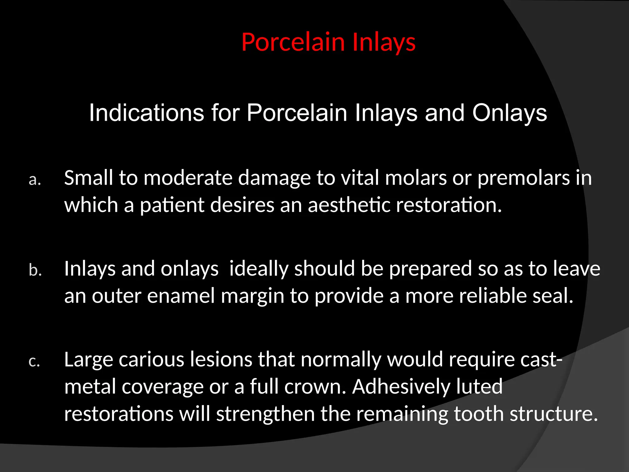
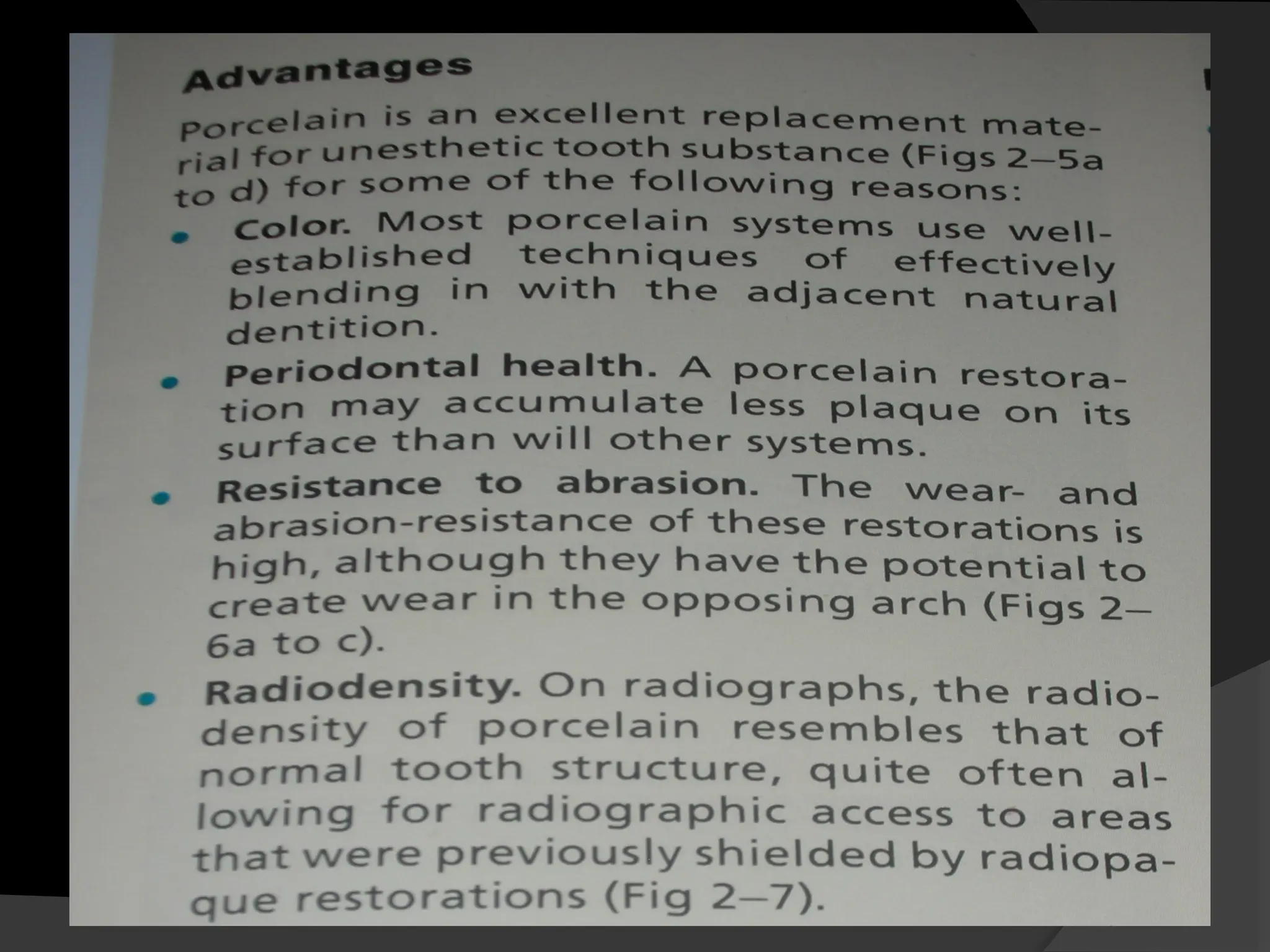
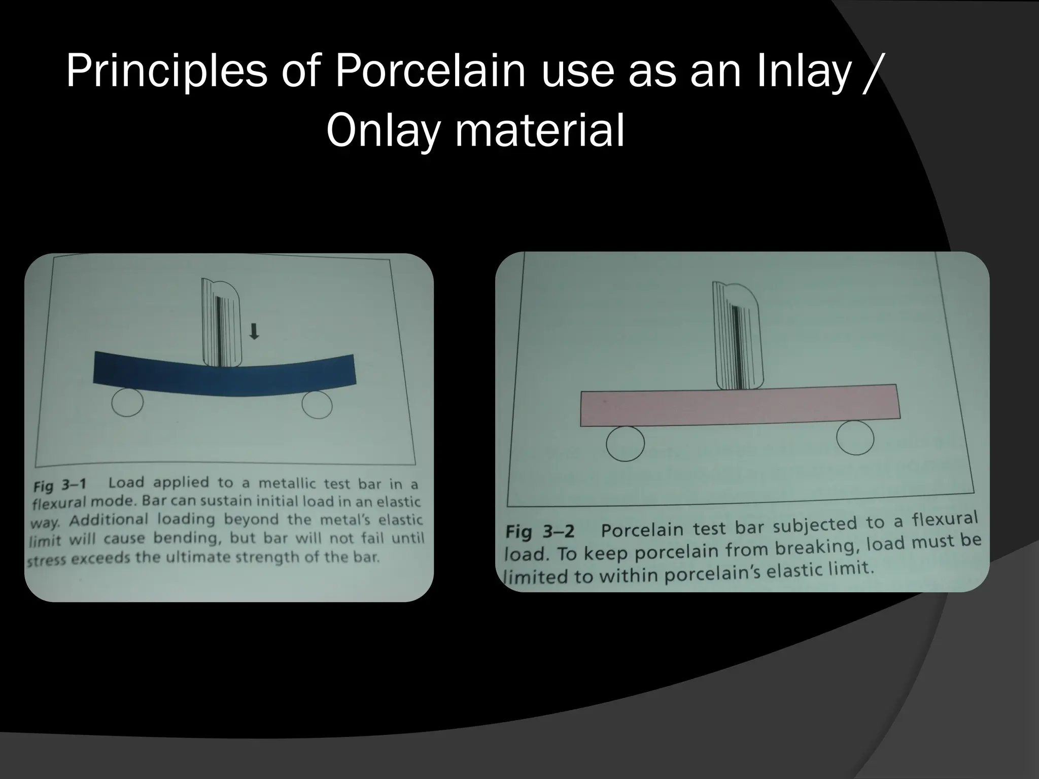
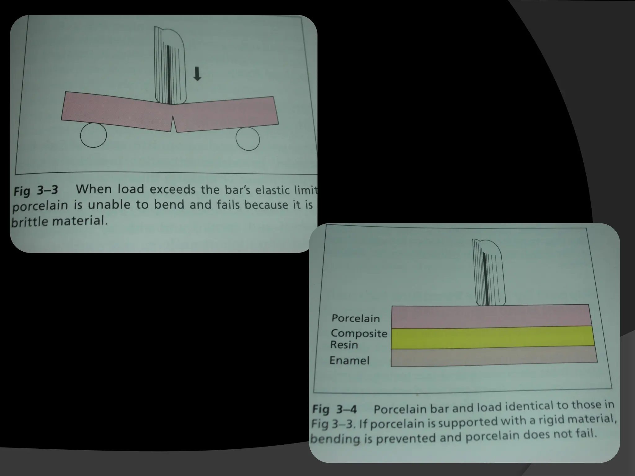
INLAYS AND ONLAYS
Guided by :
Dr ANURAG JAIN
Dr SONAL BANSAL
Dr SAURABH MANKELIYA
Presented by – Dr. Aishwarya Khare
2nd
year PG
History of Cast Restorations
 1st
cast gold inlay was made by Dr. Philbrook
 1907 William Taggart introduced Investment Casting.
 In 1945 George D. Ester improved the inlay technique.
 He introduced method of investing wax pattern in a
vaccum.
 Which prevented the formation of air bubble on the
surface of the wax patterns, as it was being invested.
ADVANTAGES
1. Yield, Compressive, tensile and shear strength of alloys and
ceramics are far greater then any other material used intra-orally.
2. Reproduce precise form and minute details.
3. Biocompatibility – unaffected by tarnish and corossion.
4. Building of restoration instantaneously rather then incremental
build up – cause fewer voids, no layering effects, less internal
stresses. Even stress patterns of the entire structure.
5. Finished, polished outside the oral cavity without endangering
the Pulp.
Disadvantages:
a) Several inter-phases will be created at the tooth-
cement-casting junction.
b) Cast restoration necessitate extensIve tooth
involvement which created hazards for VITAL
dental tissues.
c) Galvanic Deterioration.
d) Procedure is lengthy and cast alloys are Expensive.
e) Abrasion differentiation lead to imbalance in
occlusion resulting in teeth shifting, tilting or
rotating.
INDICATIONS:
1. Extensive tooth involvement.
2. As an Adjunct to successful periodontal therapy
3. Correction of Occlusion.
4. Restoration of Endodontically treated teeth
5. Support for and preparatory to partial or complete
dentures.
6. Partially Sub-gingival restorations.
With the Exception of high fused porcelain, cast ceramics and
Cohesive gold foil.
7.Low incidences of Plaque Accumulation and decay.
8. Cracked Teeth
- Prevents further propagation of the crack.
9. Esthetics.
Contraindications:
a. Developing and Deciduous teeth
Growth and resorption may be affected by
traumatic nature of procedure.
b. High Plaque/ Caries indices
c. Occlusal disharmony
d. Dissimilar metals.
Mouth Preparation Prior to Cast Restorations
1. Control of Plaque
2. Control of caries
3. Control of Periodontal Problems.
4. Proper Foundation.
5. Control of Pulpal condition of the tooth.
6. Occlusal Equilibration
7. Diagnostic WAX-up.
Principles of Cavity Tooth Preparation
A. Preparation Path
 Single insertion path opposite to the
direction of occlusal loading.
B. Apico-occlusal taper of preparation
 For max Retention opposing walls and
axial surfaces should be parallel.
 Slight divergence of opposing walls
intra-coronally.
 Taper should be an avg of 2-5 ° from the path of
insertion.
Decreased or Increased According to :
1. Length of the Perparation wall and/or axial surfaces
- Greater the wall length  More the taper
( Not exceed 10°)
- Less the wall length  Less the taper
2. Dimension & Details of surface involvement & internal
anatomy in the preparation
- Greater the surface involvement and more detailed the
internal anatomy
- Greater will be the friction b/w the preparation and the
materials contacting.
- To Diminish the friction taper is increased.
3. The Need for Retention
- Greater the need for retention, more need of
parallelism.
- Less Taper
 Most favorable for taper to be done equally at the
expense of 2 opposing walls.
 Can be done, solely at the expense of one side only if the
opposing side is absolutely parallel to the insertion path.
 No circumstances, one side having more taper than the
other.
 Create 2 planes – inner plane parallel to each other and
outer planes different taper.
C. Preparation features of the Circumferential Tie
 Peripheral Marginal Anatomy of the Preparation is called
“Circumferential Tie”
If the margin ends in the enamel,
Requirements Advocated by “NOY” for ideal Cavity Wall:
a. Enamel must be supported by sound dentin
b. Enamel rods forming the Cavo-surface margin should be
continuous with the sound dentin.
c. Enamel rods forming the Cavo-surface margin should be
cornered with the restorative material.
d. Angular Cavo-surface margins be trimmed.
For the Occlusal and the Gingival walls, the
circumferential tie :
In the form of “BEVEL”
Types & Design Features of Occlusal and
Gingival Bevels :
1. Partial Bevel
 Involves part of the enamel wall, not
exceeding 2/3rd
of its dimensions.
 Not used in cast restorations.
2. Short Bevel
 Includes entire enamel wall, but not Dentin.
 Uses with Class I alloys specially type1 and 2.
3. Long Bevel
 Includes all enamel wall and upto ½ of the
Dentinal walls.
Adv : it preserves the internal “ Boxed up”
retention and resistance features or prep.
4.Full Bevel
 Includes all the dentinal and enamel walls of the cavity wall
or floor.
Disadv : Deprives the preparation of internal resistance and
retention
5. Counter Bevel
Used when capping the cusps to protect and support them.
6.Hollow Ground (Concave Bevel)
 Bevels are ideal for Class IV and V cast materials/
FUNCTIONS OF OCCLUSAL AND GINGIVAL
BEVELS
 Bevels create an Obtuse Angled Marginal tooth
structure  Bulkiest and strongest
Configuration
 Produce and Acute angled Marginal Cast Alloy
 easily Burnished.
 Eliminates or decrease the Cement line.
 One of the major retention forms for fast
restorations.
 Are “Flexible extensions”  include Surface
defects, supplementary grooves.
TYPES OF FACIAL AND LINGUAL FLARES
I) Primary Flare
II) Secondary Flare
PRIMARY FLARE :
 Always have a specific angulation – 45° to the
inner dentinal wall proper.
 They may be hollow ground if they are a part of
circumferential tie and the preparation is for
Cast Ceramics.
Functions and Indications of Primary Flares
 Brings the Facial and lingual margins of the cavity
preparation to cleansable finishable areas.
 Indicated for any Facial or lingual wall of an intra-
coronal prep.
SECONDARY FLARE
 Flat plane superimposed peripherally to a
primary flare.
 Have different angulations, involvement and
extend depending on there function.
Functions and Indications of Secondary Flares
a. In very widely extended lesions Bucco-lingually
 The primary flare will end with acute angled
marginal tooth structure and unsupported
enamel.
 Secondary flare superimposed created the
obtuse angle of the marginal tooth structure.
b. In very broad contact area or Malposed contact
area
Primary flare does bring the facial &/or lingual
margins to finish able cleansable areas
The 2° flare accomplishes it without changing the
45° angle of the primary flare.
c. In Ovoid teeth
Peripheral undercuts are present Occluso-apically on
the facial and/ or lingual peripheries.
 Secondary flares can eliminate the undercuts with
minimal sacrifice of the tooth structure.
d. Surface defects or decalcification
Types of Margins in Cast Restorations
VARIATIONS IN PROXIMAL MARGINAL
DESIGNS
It vary depending upon :
a. The extent of tooth tissue loss.
b. Location of that loss.
c. Tooth form i.e Curvatures or embrasures
d. The positional relationship with Adjacent
teeth.
e. Need for retention
f. Convenience.
They Can be of 4 types :
1. Box Preparation
2. Slice Preparation
3. Flare Preparation
4. Auxiliary Slice (Modified Slice)
INLAY
 Acc to Sikri - INLAY is primarily an intra-coronal
cast restoration that is designed mainly to
restore occlusal and proximal surfaces of post
teeth without involving the cusps and rarely the
proximal surfaces of anterior teeth.
 Acc to Sturdevant – Inlay involves the occlusal
and proximal surfaces of post teeth and may
cusp one or more, but not all of the cusps.
Indications :
1. The Cavity width does not exceed 1/3rd
the
inter-cuspal distance.
2. Strong self resistant Cusps remain.
3. Teeth have minimal or no Occlusal facets & if
present reconfined to Occlusal surface.
4. Tooth is not to be an abutment or fixed or
removable prosthesis.
5. Occlusion not to be changed by the restoration
procedure.
Features of inlay preparation :
 Pulpal floor and the axial wall must be in the
dentin.
 Pulpal floor – must be flat and supported by
dentin.
 The pulpal floor is positioned approx 0.5 mm
into the dentin below the central groove.
 The gingival floor should be on the sound
tooth structure.
 The walls should taper from each
other on avg of 2-5° or be parallel to
each other.
 The occlusal bevel, which is a long
bevel will have an average
Angulation of 30-45° to the long axis
of the crown.
 The angulation should increase as
the width of the cavity increases.
 Angulation of bevels decreases with
steepness of the cusps.
Line angles
- Should be well defined.
- Axiopulpal line angle is rounded.
- The flare of the proximal walls should form the
Axiopulpal angles of 100-110° .
Retention :
- Occlusal dove tail
- Taper of the walls of 2-5°
- Frictional retention – can be achieved by the
action of dentin and enamel walls grasping the
restoration.
Resistance –
- Pulpal floor should be flat
- Should be perpendicular to the line of forces
- Well defined line angles
- Increased dept of the cavity.
ONLAYS
According to Marzouk – Onlay is a partly
intracoronal and partly extracoronal type of
restoration, which has cuspal protection as the
main feature.
According to Sturdevant - Class II onlay involves
the proximal surfaces of posterior tooth and
caps all the cusps.
Cast metal Onlay by definition caps all the cusps
of a posterior tooth & designed to help
strengthen a tooth that has been weakened by
caries or previous restorative experience.
Indications :
i. In the cast restoration, cuspal protection is considered when
the width of the lesion is ⅟₃rd
to ½ of the inter-cuspal
distance.
ii. Cuspal protection is mandatory ; if the width of the lesion
exceeds ½ of the inter-cuspal distance.
iii. Cuspal protection is considered in the tooth prep, if the
length: width ratio of cusp is more than 1: 1 and not
exceeding 2: 1.
iv. Cuspal protection is mandatory ; if the length to width rtio of
the cusp is more then 2:1 .
v. Whenever there is need to change the dimension,
shape and interrelationship of the occluding tooth
surfaces .
vi. Onlay are ideal restoration for abutment teeth for
removable or fixed prosthesis.
vii. Onlays are the ideal supporting restorations for
remaining tooth structure.
viii. Indicated when it is necessary to include the wear
facets that exceed the cusp tips and the triangular
ridge .
Gold inlay failures and Causes
Six causes of gold inlay failures are
1. Recurrent caries.
2. Periodontal breakdown.
3. Sensitive teeth.
4. Tooth fracture.
5. Poor esthetics.
6. Loss of retention.
Recurrent caries-
 Under-extension of the outline form could be responsible for
incomplete eradication of all pits and fissures
 Also, inadequate buccal and lingual extension of the proximal
portion into cleansable areas
 Failure to join the gingival and proximal bevels creates a
precarious butt joint at this angle.
 When making onlays, extend the preparation to an MOD
before tipping the cusps if adjacent teeth are present.
This will preclude preparing a margin at the contact area
Periodontal breakdown
 A weak contact area or a contact which is too wide or
too narrow contributes to periodontal disease.
 Sometimes, when a contact is soldered, a pimple-like
contour results which is too small to adequately protect
the underlying supporting tissues.
 The use of a too-hard or too-soft gold causes unequal
wear and creates faulty occlusion.
 Onlays should not widen the occlusal table beyond the
original occlusal dimensions.
Sensitive teeth
 Traumatic occlusion is a common cause of tooth
sensitivity.
 Postoperative pain may also be caused by
overheating the pulp as a result of inadequate
cooling during cavity preparation or finishing and
polishing.
Tooth Fracture
 Tooth fracture may be avoided by tipping
weakened cusps or making onlays, especially
for MOD preparations.
 Following endodontic therapy, all cusps should
be protected with onlays.
Poor Esthetics
 A slice preparation on the mesial surface of upper
premolars and molars may prove to be unsightly.
 This is especially true for the upper first premolar.
Loss Of Retention
 Shallow preparations invite loss of retention.
 The preparation must be deeper when the enamel
is thin.
 When making an onlay, the preparation must be
deeper than usual since cusp reduction results in
shorter walls
HISTORY OF PORCELAIN INLAYS
 Word Ceramic is derived from the Greek
“Keramos” (pottery) meaning “ of or pertaining
pottery, especially as an art”.
 Porcelain is defined as a “ fine kind of
earthenware, having a translucent body and a
transparent glaze, or as an article or vessel
made of porcelain”.
1. 1880-1890
 Inlays of “pulverized” glass were advocated by
Herbst of Germany in 1882.
 Land devised the Metal foil technique as a
impression technique.
 Land in 1884 pioneered the development of the first
gas furnace for using porcelain.
2. 1890-1900
 Custer is 1894 developed the first electric
furnace
 Introduction of low fusing inlays by jenkins in
1898.
3.1900-1910
 Introduction of mineral stains in 1904
4.1930-1950
 Special translucent inlay cements were
introduced to overcome the problems of
matching color and translucence.
Sir Norman Bennett cited 3 methods of fitting an
inlay to the prepared cavity:
1. Grinding ready made Porcelain to shape.
Various methods by which this could be achieved:
a. Cutting a piece of artificial tooth to shape.
b. Dalls method – this was confined to labial
cavities which could be reduced to a circular
form.
c. The Howard method- included the fitting to the
cavity of a ready made porcelain rod which was
dovetail in cross section and tapered from the
larger to smaller ends , so that inlay of any size
could be obtained.
2. Firing Porcelain
3. Casting Porcelain
Howard Inlay Rod
Howard inlay rod Cross-section
Various techniques were described by which
Porcelain Inlays could be made :
a. Direct method using Platinum foil.
b. Indirect method using Platinum foil.
c. Indirect method without platinum but using a
refractory investment material.
d. Dall’s method
e. Peck’s method – A platinum matrix swaged to
the impression.
f. Cast method.
5. 1960-1970
 In descending order of preferences class 5,4 and class 3 were
considered suitable for Porcelain restorations.
 Abusive bite and exposure to Occlusal stresses were
contraindications.
Methods by which porcelain inlays could be made included :
1. The Direct method using platinum foil.
2. The indirect method using platinum foil.
3. The indirect method using refractory investment material.
6. 1970-1980
 In 1978, Brinker used a platinum matrix and a
new, prefired, small particle sized, homogenous
porcelain powder.
 Resulting in short, low temp sintering cycle.
 Advantage : inlay could be fired while the patient
was in chair.
7. 1980-1990
 Denies, described – the fitting surfaces of the inlays &
onlays made from the laboratory fired low fusing
porcelain can be etched with hydrofluoric acid before
the application of silane liquid.
 Enhances the porcelain to composite bond.
 Hobo and Kyocera Bioceram Group developed a
Castable Apatite Ceramic.
 Melts at 1460 degree C and flows like a molten glass.
 Known as CERAPEARL
COMPOSITE INLAYS
Defined as a restoration which is cemented into a
dental cavity as a solid mass that has been
fabricated from composite resin with a form
established either by an indirect or direct
procedure outside the oral cavity.
Need For Composite Inlays
a. Polymerization shrinkage of resin during curing leads to
marginal defects, cuspal distortion, crack propagation and
formation within the tooth tissue resulting in post
operative sensitivity.
b. Difficulty in achieving an adequate bond in areas where the
cavo-surface margin in situated in dentin.
c. Difficulty in achieving adequate polymerization in deep
proximal areas leading to partly cured interface
susceptible to leakage.
d. Increased wear in load bearing areas.
e. Contour, contacts and marginal adaptations
are not proper.
Indications of Composite resin Inlay :
a. Restoration of conservative cavity preparation that have an
isthmus of less then 1/3rd
of the intercuspal distance.
b. Replacement of post composite resin restoration that need
replacement coz of fracture, wear or recurrent caries.
c. Replacement of existing metallic restoration for esthetic
reasons.
d. Esthetic restoration of the teeth in patients with bruxism
or clenching and exhibit mild to moderate wear on the
opposite direction.
Classification of Composite Inlays
A. Method of Construction
- Direct technique
- Indirect Technique
B. Method of curing
- Superficial / Super-cured inlays.
- Conventional cured inlays.
- Secondary Cured inlays.
Superficial Inlay :
 The inlays are cured at elevated temp & under
pressure in one stage.
 Composite employed is Heat cured rather then light
cured.
E.G – SR Isosit system  inlays are cured at 120° C
under pressure.
Conventional cured inlays :
 One mode of curing only.
E.G – Light curing ( EOS system) where the inlay is cured with
light only.
Secondary Cured inlays
 Initial curing at room temp by light
 Followed by additional curing by heat and light.
E.G –
Coltene Brilliant Aesthetic line system – in which the
secondary curing is done under high intensity light at
120°C for 7 min.
Kulzer Inlay System – in which secondary curing is done
in an enclosed light activating unit.
C. Types of Composite
A. Microfilled composite – e.g SR Isosit
B. Fine Hybrid Composite – e.g Coltene Brilliant
C. Coarse Hybrid Composite – Kulzer inlays
INDIRECT COMPOSITE INLAY SYSTEM
1. SR Isosit Inlay System
 Reported in dental literature in 1983.
 Commercially available in 1986
Homogenous filled composite contains :
- 55% by weight radiolucent colloidal silica.
- 20% radiopaque lanthanium fluoride.
Available in –
- 7 Non-vita shades
- 6 Mix in colors
 Inlays after shaping on a die are subjected to heat
and pressure polymerisation, a temp of 120°C and 6
bar pressure for 10 min.
2. Coltene Brilliant
 Was introduced by “Coltene” in 1986.
 Incorporates a fine particle size (0.5 mm) hybrid composite
containing –
- 78.5% ( by mass) glass fiber.
 The inlay is built in increments and light cured on a
laboratory fabricated die
 Further polymerized in the Coltene DI 500 light/heat curing
oven for 7 min at a temp of 120°C
3. Kulzer Inlay
 Employs Estilux Posterior CVS composite, a glass ceramic
filled composite Containing –
- 80% filler by mass.
 Direct inlays are produce intra-orally & indirect inlays on die
by conventional light curing
 Then tempered for either 180 sec in the Dentacolor XS light
Unit OR 6 min in light box
4. Visio Gem
 Initially introduced for anterior composite
veneers.
 Now include indirect Inlays.
 Inlays are initially light cured followed by a 15
min light cure under vaccum.
Second Generation Laboratory Composite
Resins for Indirect Restorations
 Most second generation composite resins (e.g., Targis and
Conquest) require a postcuring process which requires heat
and light post-polymerization after completion
(photothermic treatment).
 Some of them use a postcuring process under heat and
nitrogen pressure
(e.g., Belleglass HP).
The First generation had –
- low flexural strength.
- low resistance to abrasion.
- low modulus of elasticity.
- high polymerization shrinkage
- tendency to fracture.
Second generation composite resins (ceramic
polymers) provide:
 Good Esthetics, with a wide range of hue, chroma, and
opacity.
 Biocompatibility.
 Tissue preservation
 The flexural strength of second generation composite resins
is in the range of 120 to 150 MPa, higher than that of
feldspathic ceramic.
Fi g. ArtGlass (Kulzer) temporary
bridge without metal Substructure.
Targis (Ivoclar) long-term temporary
bridge on a metallic framework.
Cavity preparation for composite
inlay & Onlay
Technique classified into three (Dietschi and
holz,1990)
Dental amalgam has been used successfully by dentists for decades.
However, increasing numbers of patients and dentists opt for
restorative materials other than amalgam for esthetic reasons.
With the introduction of resin composites in the dental market in the
1960s, a new perspective appeared in restorative dentistry.
Although the use of resin composites has grown considerably, many
problems are associated with their use in the posterior region such as
high polymerization shrinkage, gap formation, occlusal wear, and color
instability.
In vivo studies have reported poor wear resistance in contact areas,
difficulty in generating proximal contour and contact, lack of marginal
integrity, and postoperative sensitivity.
To address these clinical challenges, manufacturers developed
materials and techniques for the indirect construction of resin
composite restorations.
INDIRECT COMPOSITE INLAYS
 Laboratory-processed resins generally differ only in their method of
polymerization, which more completely cures the composites (it has
a higher conversion rate from monomer to polymer)
 This has resulted in a reduction in the amount of intraoral
polymerization shrinkage, better control of proximal restoration
contours, improved control over marginal adaptation, enhanced
physical properties of the restorative material, improved polishability
, less water solubility, and increased hardness.
 Disadvantages most frequently associated with the indirect technique
are that it requires two appointments, there is technique sensitivity
associated with managing impression materials and dies, it requires
more time to place than the direct technique, and it is more costly
compared to direct restorations.
 However, there are few clinical studies
evaluating the clinical performance of indirect
posterior resin restorations.
 Wendt and Leinfelder conducted a three-
year clinical trial that demonstrated the
success of this procedure.
 They found that indirect heat–treated resin
composite inlays performed better than
conventional indirect light–cured resin
composite inlays in the categories of marginal
integrity and interfacial staining.
Clinical steps for indirect composite
inlays
 composite inlays using the indirect technique
requires a reasoned dental preparation and a
precise impression.
 The coordination with the laboratory must be
worked and honed to facilitate the clinical steps
of fitting, bonding under a dental dam, removal
of excess bonding material ,occlusion control
and final polishing.
 The clinical examination of the tooth is completed by
vitality tests; the tooth must be vital and without any sign
of pulpal involvement.
 We must proceed to a study of the carious extension on
radiogram, to objectify the relation of the decay with the
pulpal tissue and the periodontal structures, in case of a
proximal lesion.
 After elaborating a diagnosis, we proceed to a complete
elimination of the altered tissues with maximum
preservation of healthy tissue.
 A dental dam is put in place to isolate the operative field.
Its utilization is imperative in order to work in a dry and
aseptic operating environment.
 The undercuts are filled with dentinal substitute materials
such as Glass-ionomer cements or flow composites, with
no additional preparation for the healthy dental structures.
 The accurate impression is made using silicone materials.
 The impression is made in a single-step with dual-
viscosity technique, then sent to the laboratory for casting
of the composite inlay.
 The impression of the antagonist was realized with
alginate to allow the reproduction of the occlusion reports
 The preparation is protected with a temporary filling while
waiting for the next appointment .
 The manufacturing of the composite inlay will be done at
the laboratory.
 The stratification built up allows to accurately mimic the
optical properties of the natural tooth (Figure 5).
 The underside of the inlay is treated following these steps:
 A. Post light curing treatment with heat and light
(80 to 140°)in specific containers, with or without
nitrogen pressure.
 This final cooking phase improve the mechanical
properties of the composite, its marginal integrity
as well as its surface topography.
 Moreover, this post light curing phase increases
the conversion rate of the composite.
 The sanding with 50 m alumina oxide is combined
to etching with 5% hydrofluoric acid for 1 minute,
followed by application of a layer of silane to
promote the adhesion.
 b. Once the inlay is received, we try it in the
tooth under a dental dam isolation.
 Any contact with the mouth fluids will cause a
readmission of the inlay to the laboratory to
resume sanding, etching and silanization
treatments (Figure 6).
 c. During this step, functional and margins
adjustment are done if necessary.
 d. The bonding of the inlay is made after
treatment of the tooth surface, enamel and
dentin etching during 20 seconds, 20 seconds
rinsing, drying and application of the 4th or 5th
generation bonding system. (Figure 7)
 e. The chemical treatment of the tooth surface allows an
adhesion of the composite by micro-locking in the enamel
and the hybrid layer in the dentin by tangling between the
adhesive system and the dentin collagen matrix which
allows the bonding(Figure 8)
 f. For the proximal cavities the use of a matrix system is
recommended to avoid any cervical excess .
 g. The bonding is assured with a dual flow
composite, chemical and light cured composite
(Figure 10).
 The composite is places in the cavity, then the
inlay with a slight pressure.
 We proceed to the elimination of all the excess of the
composite material before the polymerization using a
dental probe for the occlusal surfaces and dental floss for
the proximal zones.
 Then we proceed to the polymerization of all the tooth
walls, then polishing and finishing using fine diamond burs
and disks
 Regular clinical and radiological controls of the inlay are
recommended to follow the evolution of the dentin-pulp
structures and to appreciate the behaviour of the material
over time.
 Thus, it is possible to detect any marginal deterioration or
lack of tightness of the filling (Figures 11 & 12).
SEMIDIRECT COMPOSITE INLAY
 A simplified chairside method called “semidirect technique”
was introduced and developed in the1980s.
 in 1985, the treatment time and the laboratory steps were
reduced. Nevertheless, the cost is still high compared with the
direct restoration, and the technology remains expensive.
 In this technique, the dentist himself fabricates the restoration
with an intraoral or extraoral procedure during a single
appointment.
 In the intraoral approach, the restoration is fabricated by
placing directly the composite increments on the isolated
tooth’s cavity.
 After in-mouth polymerization, the workpiece is
removed and finished/polished extraorally, followed by
the luting of the restoration.
 Although the intraoral approach could be the most
accurate in respect to marginal fit, as the restoration is
made directly in the cavity.
 the main disadvantage of this approach is the difficulty
of removing the restoration after composite resin
hardening.
 This is mainly due to the cavity configuration and the
microretentions created by the diamond burs used for
preparation.
 That confines its use to simple cavities
(occlusal,mesio-occlusal, or disto-occlusal) with a
regular design and highly divergent walls.
 In the extraoral approach, a silicon-working model is
fabricated from the impression of the cavity in order to
build-up the restoration chairside extraorally.
 This approach offers an advantage over the intraoral
one as less divergent cavity walls are required; thus, a
more conservative preparation can be realized.
 However, the freehand semidirect technique is more
sensitive to the cavity configuration design than the
CAD/CAM technique, e.g., the mesial-occlusal-distal
(MOD) cavity may cause a problem because of the
polymerization shrinkage that tends to be directed
toward the axial walls leading to lock of the restoration
that will prevent its removal.
 The major advantage of the semidirect
technique is that the dentist can provide his
patient with a low-cost indirect restoration in a
single visit.
Direct Composite Vs Indirect Composite
Inlay
 The stratification build-up associated to the large choice of
composites currently available, allow us to have the same
aesthetic properties of the direct and indirect composites.
 The mechanical properties of indirect inlays are certainly more
interesting compared to direct composites, thanks to heat
treatments and post polymerization.
 In addition, the indirect composite inlay offers better control of
cervical tightness and better restitution of the contact point in
cases of proximal loss of substance.
 The cost is certainly lower when the restoration is carried out
directly in the mouth .
 As for longevity, clinical studies have shown that there is no
significant difference between direct and indirect method inlay
 The main causes of failure are secondary
caries, fractures, marginal defects, wear and
postoperative sensitivities.
 A study conducted by the Lasfargues et al.
shows that the failures are not related to the
material, but a large part is due to the
implementation and the respect of the
operating stages.
 The choice for the direct or indirect method
will be mainly guided by the clinical situation.
 It has been observed that the restorations resulting
from indirect resin composites are relatively smaller
in size than the direct ones as a result of the extra-
oral preparation and polymerization shrinkage.
 However, the lost space has been reported to be
usually compensated by the presence of luting
cement in these restorations.
 Another advantage of the indirect resin composites
is the enhanced occlusal morphological outcomes
as a result of the good control over the contours and
other related structures because indirect composites
are usually fabricated outside the oral cavity.
 Filler contents are also more abundant in the
indirect composites than the direct ones, which
significantly enhances the physical properties of
the compounds leading to enhanced strength,
hardness, wear, and marginal integrity, and
accordingly, the prognosis with these modalities
is usually better than with the direct ones.
 indirect resin composites can be polished and
fabricated within a laboratory, they have been
reported with enhanced esthetics and better
retention outcomes that usually lasts for an
extended period over the outcomes that can be
associated with the direct composites
 clinicians can successfully obtain the pink and
white desirable esthetics results because indirect
resin composites can provide a variety of color
combinations to the tooth and adjacent gingival
tissues.
 It should be noted that the cost of indirect resin
composites is higher than the direct ones, which
is attributable to the extra laboratory work to
achieve temporization and impression.
 Additionally, increased reduction of the tooth
structure is also another disadvantage that is
usually observed with the indirect composites, a
process that is done to develop adequate removal
and insertion paths.
 It was also demonstrated that the luting thin
layer at the resin cement is subjected to
shrinkage during the luting procedure for
completion of the restoration process.
Indirect Composite Inlay Vs Ceramic
Inlay
 The aesthetic integration is the same for the both
materials, composite and ceramic.
 Indeed, the wide range of shades currently available
can mimic the tooth in its finest details.
 Thanks to the bonding, composite or ceramic inlay
helps strengthen the structure of the decayed tooth,
creating a homogeneous structure.
 The bonding also allows a good marginal adaptation,
when the different steps are respected .
 The stability of ceramics in time is well established, the
composite stability depends on the respect of the
cooking and polymerization steps, and especially a good
final polishing.
 As for the hardness, the ceramic inlay largely exceeds the
composite inlay.
 It could even cause long-term abrasion of the opposing
teeth, reason why the use of the ceramic inlay is not
indicated in the presence of parafunctional habits.
 The higher cost as well as the difficulty of manufacturing
of the ceramic inlay; would tip the balance of the
advantages of the composite inlay.
 Indirect composite inlay remains an excellent alternative,
less expensive especially in cases of bruxomania .
Fabricating an indirect composite
inlay
1
Temporary Restoration
• A provisional restoration is necessary when using indirect
systems that require two appointments.
• It protects the pulp-dentin complex in vital teeth,
• maintains the position of the prepared tooth in the arch,
• protects the soft tissues adjacent to prepared areas.
• Care should be taken to avoid the bonding of the temporary
material to the preparation at this phase of the procedure.
• For exceptionally non retentive preparations, or when the
temporary phase is expected to last longer than 2 to 3 weeks,
zinc phosphate or polycarboxylate cement can be used to
increase retention of the temporary restoration.
 An interim restoration should have the following features:
• Non irritating
• Esthetically satisfactory
• Easy to clean and maintain
• Protect and maintain the health of periodontium
• Adequate strength and retention to withstand the
masticatory forces.
Normally, the interim restorations are made up of
acrylic resin. they can be prepared by direct and indirect
methods
Try-in and Cementation
• Try in is more demanding step, because
(1) the relatively fragile nature of the ceramic or
composite material,
(2) the requirement of near-perfect moisture control,
(3) the use of composite cements
• The ceramic or composite inlay is relatively fragile
until it is bonded in place with composite cement.
• Very little pressure should be applied to the
restoration during try-in.(fragile)
• Thus occlusal evaluation and adjustment are
delayed until after cementation.
Finishing
For indirect composite restorations, finishing
may be started with 12-fluted carbide finishing
burs Instead of diamonds
Common failures
 Bulk fracture
 Occur from placing the restoration in a
tooth where it should not have been
indicated, such as in bruxers and
clenchers, or from lack of appropriate
restoration thickness derived from lack of
tooth preparation.
 If bulk fracture occurs, replacement of the
restoration is almost always indicated
Repair
 For composite and ceramic inlays, the repair
procedure is initiated by mechanical roughening of
the involved surface.
• a coarse diamond may be used, a better result is
obtained with the use of air abrading or grit
blasting with aluminum oxide particles and a
special intraoral device
• A brief application of phosphoric acid can be used
to clean the composite surface after roughening.
TOOTH PREPARATION
 All line angles & point angles are rounded.
 Etched Porcelain or composite inlays requires “NO Classic
Bevel” to aid in sealing of the restoration.
 Classic bevel is contraindicated as it necessitate the
fabrication of thin edge of porcelain which will tend to
fracture.
 Hollow ground Chamfer confined to marginal
enamel aid in developing a more effective seal.
Clinical Principles of Tooth Preparation
1. Removal of old restorative material &/ or caries.
2. Isolation
3. Pulpal Floor
- Developed by combination of calculated and
judicious tooth reduction and GIC base.
- Decreases the shearing forces on the composite-resin
luting agent interface.
Configuration of the pulpal floor vary according to the dept of
preparation –
if the cavity is shallow, the pulpal floor should be indented in
the central fossa region to parallel the Cuspal inclines.
Results in thickness of porcelain in the center.
4. Axial Walls
 The axial walls are slightly more divergent from
the pulpal floor toward the enamel surface.
 6-10° taper
 This allows easier placement and removal of
restoration.
5. Finish Lines
 Cavosurface Margin of restoration should not be
bevelled.
Two school of thought on configuration of finish line:
a. Well defined smooth Butt joint
b. A hollow ground chamfer
6. Internal line angles
The typically well define internal line & point
angles of a cast restoration are ROUNDED
Resistance and retention form
- Primarily by adhesion to enamel and dentin.
- Resistance form is incorporated with rounded
proximal boxes.
- The walls & floor of the prep should be smooth and
even and the internal angles should be rounded to
enhance the adaptation of the restorative material.
- The Occlusal reduction should be anatomic and
uniformly a min of 2mm for strength.
- Bevels avoided.
- A 90° butt joint minimizes the chipping.
- Long chamfer on facial surfaces.
INLAYS VERSUS ONLAYS
 The adhesive nature of the bonded restoration makes it
unnecessary for additional preparation to protect
unsupported cusps or to develop resistance and retention
form.
 Removal of additional tooth structure for onlay cusp is
Contraindicated  It results in a porcelain cusp in occlusal
contact with the opposing central fossa.
 The occlusal scheme should be developed so that during
lateral excursion of the mandible minimal or no contact is
with Porcelain
Cuspal Onlay Preparation
Should incorporate following features :
a. A 1.5 to 2 mm reduction in vertical height of the cusps and
all occluding areas.
b. Preparation finish lines on any supporting cusps that are
Hollow Ground chamfers; without bevels.
c. Well rounded angles on the cuspal preparation, to prevent
propagation of porcelain fracture from the sharp stress
points.
Indications for Porcelain Inlays and Onlays
a. Small to moderate damage to vital molars or premolars in
which a patient desires an aesthetic restoration.
b. Inlays and onlays ideally should be prepared so as to leave
an outer enamel margin to provide a more reliable seal.
c. Large carious lesions that normally would require cast-
metal coverage or a full crown. Adhesively luted
restorations will strengthen the remaining tooth structure.
Porcelain Inlays
d. An etched onlay restoration can sometimes be used as a
conservative alternative to a post, core, and crown.
e. Teeth that would normally require pins, crown lengthening,
or intentional endodontic treatment can sometimes be
restored with adhesive restorations.
f. Patients with metal allergies.
Contraindications For Porcelain Inlays And Onlays:
a. Patients with parafunctional habits, especially bruxism.
b. Poor oral hygiene. Recurrent decay around these
restorations would necessitate full coverage.
c. Appropriate access must be obtainable so that proper
preparation, impression, and adhesive luting with rubber
dam can be achieved.
d. Short teeth may present a problem because adequate
depth of the preparation cannot be achieved.
e. Patients with gold or composite restorations in the
opposing arch may exhibit excessive wear with ceramic
onlays.
f. Technical difficulty of placement.
g. Subgingival margins may preclude adequate isolation.
Principles of Porcelain use as an Inlay /
Onlay material
The Bonding Mechanism
The improved fractures resistance brought
about by the bonding process relies on
several mechanism:
1. Support by the tooth structure to prevent
bending
 Bonding the porcelain to the tooth enamel
and dentin ensures the stability and
integrity.
 Allows the tooth structure to provide full
support to the otherwise fragile
restoration.
 The bonded restoration is protected
against displacement and deflection,
rendering it resistant against occlusal
forces.
2. Uniform support and stress-relieving layer
The polymerised composite under the bonded porcelain
restoration provides –
 A solid layer of uniform thickness and rigidity.
 The layer equalizes the variance in elasticity b/w diff tooth
structures
 Fill minute gaps and provides an adequate zone for relief of
potential stresses b/w the porcelain and underlying tooth
structure.
3. Anti-”Crack Propogation” forces
 The defects inherent to porcelain are caused
mainly by internal stressing of the ceramic
during processing. (contraction during cooling)
 This can greatly weaken a ceramic material.
 Additional porcelain Strengthening mechanism
is caused as result of Composite Resin’s
POLYMERISATION SHRINKAGE
 Composite polymerization shrinkage can
strengthen the porcelain –
- By exerting force on the inner porcelain surface
which stresses the porcelain molecules
together .
4. Transfer the stress to underlying Structures
 A well bonded Ceramic restoration adheres strongly to tooth
structure forms, similar to the enamel layer.
 Forces applied are transferred through the porcelain to the
dentin.
 If the bonding b/w the porcelain and the tooth is
inadequate, the stress will not be transferred further and the
porcelain will tend to fracture.
Classification Of All Ceramic Systems
1. Conventional powder-slurry ceramics
 These products are supplied as powders to which the
technician adds water to produce a slurry.
 Which is built up in layers on a die material to form the
contours of the restoration.
Includes – (a) Hi cream – Alumin reinforced porcelain.
(b) Optec HSP – Leucite reinforced porcelain.
(c) Duceram LFC – Hypothermal Low fuing Ceramic
2. Castable ceramics
 Are supplied as solid ceramic ingots, which are used for
fabrication of cores or full-contour restorations using a lost-
wax and centrifugal-casting technique.
 One shade of material is available.
 Covered by conventional feldspathic porcelain or is stained
to obtain proper shading and characterization of the final
restoration.
Include : a) Dicor
b) Cera Pearl
Machinable ceramics
 Are supplied as ceramic ingots in various shades and are used
in computer-aided design–computer-aided manufacturing, or
CAD-CAM, procedures.
Includes :
a. Ceres Vitablocs mark I and II
b. Celay Blocks.
c. Dicor MGC.
Pressable ceramics
 Supplied as ceramic ingots, these products are melted at
high temperatures and pressed into a mold created using the
lost-wax technique.
 The pressed form can be made to full contour, or can be
used as a substrate for conventional feldspathic porcelain
build up.
Includes – (1) IPS Empress.
(2) optic pressable ceramics.
Infiltrated ceramics
 Are supplied as two components:
- A powder (aluminum oxide or spinel), which is fabricated into
a porous substrate.
- A glass, which is infiltrated at high temperature into the
porous substrate.
Includes :
- In cream.
Classification of Ceramic Inlays
A. Inlays produced on refractory die.
B. Inlays fired on platinum foil.
C. Inlays made by lost wax technique/ Cast
ceramic inlays.
D. Machined ceramic inlays.
Cavity Preparation
 Cavity prep for porcelain inlays is
similar to cast metal minus
BEVELLING AND SECONDARY
FLARING.
 Occlusal Divergence – 6 to 8°as
compared to conventional 2-5
for Cast metal restortions.
 Ceramic requires a min thickness
of 1.0 mm for its strength.
 Dept of Occlusal step – 1.5 –
2mm for all ceramic Systems.
 Width of the Isthmus – 1.5 mm
 Axial reduction in the proximal
box – avg 1.5 mm
 For DICOR restoration : Axial
Reduction – 1.2 mm
 For Optec System Axial
Reduction – 1.0 mm
In the proximal Box :
- Facial, lingual and Gingival walls should clear the
adjacent tooth by 0.5 mm
- The gingival margin should be placed at levels where
adequate enamel is present for bonding.
- Cavosurface margins should terminate in a butt joint.
Cusp Capping –
 Functional cusp reduction
- On premolars 1.5 mm
- On Molar 2.5mm
 Non-functional cusp requires – 1.0 to 1.5 mm
 Capping functional cusp – Collar is made .
 width of the Collar – 1.0 – 1.5 mm
INLAYS FIRED ON A PLATINUM FOIL
Stages in the construction of inlay :
1. Preparation of the cavity
2. Making a platinum matrix which closely fits
the cavity.
3. Fusing porcelain into the matrix to restore
the tooth form.
4. Glazing
5. Removing the matrix from the inlay
6. Cementing the inlay into the cavity.
 A matrix is required into which the porcelain powder can be
built and fused.
The matrix can be obtained in several ways:
1. Direct – making it directly in the tooth cavity.
2. Indirect – by taking an accurate impression of the cavity and
then proceeding on the model.
3. Indirect-Direct – by making the matrix on the model and
then reburnishing it directly in the tooth cavity.
PORCELAIN INLAYS FIRED ON REFRACTORY DIES
 This method eliminated the use of platinum foil, which in
part causes inaccuracy and deformation.
Procedure :
- After the cavity has been prepared .An impression is taken
and a master working cast in poured in die stone or epoxy
resin.
- Die spacer is applied to the cavity .
- The master model is then duplicated with the silicone
impression and poured in the refractory investment capable
of withstanding porcelain firing temp.
- The cast is fired at 100°C to eliminate the decomposition gas.
- Soaked in a conditioning solution.
- It enables the Porcelain contraction to be directed toward
the cavity itself.
- Porcelain is added into the cavity and fired in an oven.
- 2 or 3 step build up is done to compensate for the firing
shrinkage.
- Removed and seated on the master die for adjustment and
finishing.
- The product is finally glazed.
Advantages :
- Less expensive set up.
- Compatibility with most existing ceramic ovens.
Disadvantages :
- Technique sensitivity.
- Higher incidence of fracture compared to other ceramic
systems.
Inlays made by lost wax technique
A. Dicor ( Castable Glass Ceramic)
- Minimum reduction – 1mm
- Axial reduction – 1.2 to 1.5 mm
- Incisal or occlusal reduction – 1.5 to 2 mm
- Taper – 6-8° .
Procedure :
- Master cast in die stone or epoxy resin in poured.
- Tooth shaded die spacer is applied in 2 thin coats avoiding
the margin.
- Die lubricant is directly applied over the die spacer, and a
wax pattern is made.
- The sprued pattern is invested.
- After burning out, the Glass is cast centrifugally at 1370°C.
- Following the grit blastin with 25 micrometer alumina grains
the inlay is embedded in a special investment and ceramed
to produce crystal growth.
- Resulting inlay is translucent, so be covered by surface
glazes.
The casting ring is placed in the the
centrifugal casting instrument, which delivers
the molten glass into the pattern
B. Castable Apatite Ceramic ( CERA PEARL)
- Reduction on the occlusal surface – 2mm
- Proximal surface – 1.5 mm
- Thickness not more than 1.5 mm
Procedure :
- Wax pattern is fabricated on the die.
- The sprued was pattern is attached to ceramic crucible in
one end and on the other end is located in a preformed
silicone mold.
- The investment is mixed for 1 min under vaccum and
poured into the silicone mold.
- The silicone mold is easily separated from the set
investment after 60 min
- The ringless investment is then dried in am electric oven at
temp –
a. Less than 100° for atleast 30 min.
b. Over the next 30 min then is raised to 500° C.
c. Finally the oven temp is held at 800°C for 30 min.
- The investment mold is then transferred to high heat
processor.
- 8-10 gm raw Cerapearl is placed in the Ceramic crucible ,
melted at 1460°C under vaccum and cast into a mold.
- Ring is removed and transferred into the crystallization
oven.
- The Crystallization process is started at 750 °C and the
temp maintained for 15 min.
- Oven temp is raised t 50 °C per min until the temp of
870 °C is reached.
- Above 870°C crytals grow excessively and result in
too white appearance.
- Cera Pearl should always be seated with light finger
pressure.
- GIC is considered the best choice for a luting
agent.
- As it will adhere to both the restoration and the
tooth.
PRESSABLE CERAMIC INLAYS
 Also utilizes the Lost Wax technique.
 Differ from the other castable ceramics “ The material is
pressed into the mold under pressure and not centrifugally
driven”.
 Wax pattern of the restoration is fabricated and invested in
a phosphate bonded investment.
 Following the burn out procedure, the ring long with the
investment in placed in a specialised mould that has
alumina plunger.
 The ceramic ingot is placed under the plunger.
 The entire assembly is heated too 1150 °C.
 The plunger presses the molten ceramic into the mold.
When using the lost wax technique, the total shrinkage is
reduced as the only shrinkage, which occurs is during
cooling, can be controlled with an investment having
appropriate expansion.
MACHINED CERAMIC INLAYS
There are 2 principle machining approaches :
1. Analogous system
a. Copy milling/ grinding technique
- Automatic ( ceromatic II)
- Manual ( Celay)
b. Erosive Technique.
2. Digital Systems
 CAD-CAM Technology
COPY MILLING
 Best known Copy grinding system is “Celay”.
 Based on – first fabricating a pro type inlay (Pro Inlay) using
a resin or wax pattern
 Which is then copied using a scanning tool.
 The final restoration is then milled from preformed
ceramic block.
 Cavity preparation of Porcelain restoration should be free of
undercuts.
 Pro Inlay is fabricated with a blue resin based composite.
- directly on a prepared tooth.
- Indirectly on a die.
 It is fixed into the Celay unit.
 The surface of the pro inlay is scanned.
 A coarse diamond coated disc simultaneously roughs out
the shape of the ceramic rest.
 A fine white powder is applied on the Pro Inlay .
 Scanning is again done using smooth disc and fissured and
tapered burs.
 Once the white powder is completely traced off  Milling of
the ceramic rest is complete.
 Avg time for milling is 20-30 min.
Disadvantage – Difficulty in obtaining accurate pro inlays.
EROSION METHOD
 Ultrasonics/ Sono erosion used for grinding ceramic requires
a metal based negative form of the interior and exterior
contours of the restoration.
 Which are prepared by
- Wax moulding and casting.
- Intensive copper plating of the impression.
 These are called “SONOTRODES”.
 Both Sonotrodes fitting exactly together are into a ceramic
blank.
 The ceramic blank is surrounded by an abrasive suspension
of hard particles such as boron carbide.
 On acceleration by ultrasonics erodes the restoration of the
Ceramic block.
CAD-CAM GERNERATED INLAYS
 Mormann and Brandsetini – used the CAD-CAM
device to digitize and store cavity parameter
 And a copy milling device to then shape and put a
restoration out of the ceramic block.
 The original system was know as “Cerec I”
 In sept 1994 improved version Cerec II was
introduced.
The unit consists of :
a. Three dimensional video camera (scan head).
b. An electronic image processor memory unit.
c. A processor which is connected to a miniature milling
machine.
Diff b/w Cerec I and Cerec II
- Cerec I cannot prepare the Occlusal anatomy of
the rest.
- Cerec II is equipped with grinding wheel and
cylindrical stone which is able to finish off
undercuts at buccal extensions.
- Cerec II has definite improvement on the camera
and imaging systems.
CAVITY PREPARATION FOR CAD-CAM INLAYS
Requires conventional cavity design with slight modifications :
 NO convexities should be present in the pulpal and the
gingival walls.
 The occlusal step should be prepared
 1.5-2mm in dept.
 Isthmus or groove extension – 1.5 mm wide.
 The buccal and lingual walls of the occlusal portion of the
prep may converge towards the occlusal.
 The facial and the lingual walls of the prep in the proximal
box are prepared with slight divergence towards the
occlusal.
 Axial walls should be straight an NOT follow the convex
contour of the proximal surface of the tooth.
 No cavosurface margin or bevels should be given.
TECHNIQUE FOR CAD-CAM FABRICATED INLAYS
Five steps :
1. Computer surface Digitization
2. Computer aided designing.
3. Computer aided manufacturing.
4. Computer aided esthetics.
5. Computer aided finishing.
Surface Digitization
- Optical impression is used to collect information in the
shape of the preparation using a Scanning device.
Scanning Devices –
a. Mechanical.
b. Optical ( infra-red video camera).
- The optical sensor are not able to measure highly
transparent or reflective surfaces, so enamel has to be
covered with a powder or a water soluble color .
Limitations :
- Produces errors in measurement on steep flanks
and distorts easily.
- Undercut areas and narrow gap like fissures
cannot be explored.
The scanning devices can be applied
a. Directly on the tooth .
b. Indirectly onto model fabricated from an
impression of the cavity.
Advantages of the direct technique :
- The entire procedure is completed in one session.
- Eliminates the need of impression, dies and hence
associated inaccuracies.
- No interim restorations re required.
Disadvantages :
- Waste of chair side time in case of difficulty during milling or
designing.
- Time required in chair side is increased.
COMPUTER AIDED DESIGNING
 Step involves 3 dimensional image processing.
 Confirms the features of the preparation-
- Boundaries of the restoration.
- Position of the gingival margins.
- Proximal contacts and contours
- Buccal and lingual extensions.
COMPUTER AIDED MANUFACTURING
 The cavity surface of the inlays and onlays are milled to the
dimensions of the scanned image with diamond disks or
instruments electrically driven and lubricated with water.
 The occlusal anatomy ( when Cerec I used) is completed by
the operator using diamond burs.
 Controlled cutting of the ceramic block is done – rotation of
the block, horizontal movement of the block into the wheel
and the vertical movement of the cutting wheel.
Disadvantages :
- Initial high cost for the purchase of the ceramic
unit.
- Time and cost must be invested to master the
technique.
- Contouring the occlusal surface may still have
to be carried out by the clinician.
DOUBLE INLAY TECHNIQUE
Ceramic inlays have certain disadvantages :
1. A wide diastema between 2 teeth often results in excessive
unsupported ceramic and increases the risk of ceramic
fracture.
2. Cervical margins, located at or slightly underneath the
marginal gingiva, are poor candidates for bonding. It has
been shown that a large enamel surface is superior for
composite bond strength.
4. It has been demonstrated that there is a better bond
strength to crown dentin than to root dentin.
5. The use of a rubber dam is mandatory for proper results
with bonding techniques. Saliva, blood, or sulcular fluid
may interfere with the cementation procedure if the
preparation is located in the subgingival area.
6. Patients with parafunctional occlusal habits (grinding,
clenching, and bruxomania) are poor candidates for
ceramic restorations.
With a double-material inlay technique, 2 treatment options
are possible:
1. A 1-piece inlay
- Containing ceramic fused to gold in the laboratory.
2. A 2-piece inlay
- With a cemented metal base overlaid by a bonded porcelain
inlay.
 The major problem with the double-inlay technique is the
amount of tooth reduction needed to avoid ceramic
fracture.
 A cavity preparation of 2.5 mm is mandatory because of the
volume required for the 2 inlay components.
Procedure :
1. Prepare the occlusal cavity as a classic ceramic inlay box-
shaped preparation with an appropriate bur. The isthmus
should be as large as possible, and sharp angles should be
avoided.
2. Unlike other techniques, a minimal depth of only 1.5 mm for
the occlusal cavity is needed because the floor will not be
covered by the metal structure.
3. Prepare the proximal box for receiving the metal base
substructure . The cavity preparation should be extended
until the proximal contact with the adjacent tooth is
completely open, with a minimum thickness of 1 mm on all
sides.
4. Prepare a 1.5- to 2.0-mm dentinal pit at the floor of the
proximal cavity, parallel to the pulp chamber and to the
long axis of the root. This allows precise 3-dimensional
placement and aids in retention of the metal base.
5.Place the 0.7-mm calcinable pin into the prepared pin hole,
and make an impression with an appropriate impression
material.
6. In the laboratory, pour the impression in die stone
- Fabricate both components with the same working cast.
- Cast the metal base with ceramic gold type IV
- The gold-ceramic joint must be built above the gingival margin to
ensure accurate bonding and proper polishing.
7. Place a ceramic opaque porcelain to cover the occlusal
portion of the inlay surface.
- The opaque increases the bonding strength and also
decreases black shadow by masking the metal of the ceramic
inlay.
8. At the second appointment,
- Cement the gold inlay first with a glass ionomer cement
9. Apply bonding agents on the metal and tooth structure.
- Apply 37% phosphoric acid for 60 seconds and activate the
ceramic with a silane agent.
NATURAL INLAY
(A) extraction of the ‘48’; (B) removal of the amalgam restoration and preparation of
the ‘46’ for an adhesive inlay; (C) milling of the ‘Natural Inlay’ from the extracted
‘48’ using the CELAY machine; (D) placement of the ‘Natural Inlay’.
The clinical advantages of the NI are :
1. The bio-mechanical characteristics of this ‘restorative’
material are similar to those of the existing dentition.
2. If indeed proven, the NI will combine the two features
which are essential for the longevity of a posterior
restoration:
- An occlusal surface (enamel) wearing at the same rate
as the surrounding enamel thus ensuring no abnormal
wear to the opposing teeth
- A protective elastic support to this brittle layer, provided
by dentine.
3. An appropriate replacement for large posterior amalgam
restorations due to its expected high strength.
4. The NI makes it possible to ‘recycle’ extracted teeth, a
precious biological tissue that has been discarded until now.
5.It appears that gamma irradiation is an effective sterilisation
method for bacterial decontamination of teeth.
One obvious disadvantage of the NI is that, just like the
natural dentition, caries may develop in the
restoration itself.
CERAMOMETAL BONDED INLAYS AND ONLAYS
The advantages of the CMBR include the following:
1. More conservative preparation designs are possible.
2. Strong porcelain support
3. Improved durability
4. No potential for darkening of root
5. Better esthetic vitality, because metal is not used on
the facial surface
6. Use of conventional materials
7. Long-term clinical success
8. It is appropriate for inlays, onlays, extensive veneers, and
full-coverage restorations.
The minimum material thickness requirements of the
restoration are:
Insert: 0.3 mm
Opaque on all surfaces:0.2 mm x 2
Porcelain on internal surface:0.3 mm
External porcelain: 1.0 mm
- The minimum required reduction directly under the insert is
2.0 mm
- However, reduction of 2.5 mm is recommended.
- The additional 0.5 mm of external occlusal porcelain
contributes directly to the esthetic benefits
CONCLUSION
Esthetic inlays and onlays are more than just a restorative
alternative for moderately broken down posterior teeth,
they have indeed become a permanent part of restorative
as well as esthetic dentistry.
The tremendous improvement in adhesive technology
over the past years allows today's restorative dentist to
reinforce weakened, but otherwise healthy, tooth
structure.
References
 Operative dentistry- modern theory and practice – M.A.
Marzouk
 Textbook of operative dentistry- 2nd
edition
Vimal K sikri
 Fundamantal of operative dentistry – 2nd
edition – Summitt
 Art and science of operative dentistry – Sturdevant’s
 Porcelain inlays and Onlays - Garber
 Journal of operative dentistry -1990, 15, 61-70.
 J Prosthet Dent 2001;85:624-7.
 Journal ofDentistry, Vol. 26, No. 1, pp. 21-24, 1998
 J Esthet Dent 12: 122-1 30,2000
 JOURNAL OF ESTHETIC DENTISTRY Vol 8 no 3
 J Esthet Restor Dent 15:338-352,2003
 DCNA 2002 46 341-365
 J. Prosthet. Dent April, 1973
 JOURNAL OF ESTHETIC DENTISTRY Vol 9 no 3
 JADA 1997 March
THANK YOU

inlays and onlays powerrpoint presentation

  • 1.
    INLAYS AND ONLAYS Guidedby : Dr ANURAG JAIN Dr SONAL BANSAL Dr SAURABH MANKELIYA Presented by – Dr. Aishwarya Khare 2nd year PG
  • 2.
    History of CastRestorations  1st cast gold inlay was made by Dr. Philbrook  1907 William Taggart introduced Investment Casting.  In 1945 George D. Ester improved the inlay technique.  He introduced method of investing wax pattern in a vaccum.  Which prevented the formation of air bubble on the surface of the wax patterns, as it was being invested.
  • 3.
    ADVANTAGES 1. Yield, Compressive,tensile and shear strength of alloys and ceramics are far greater then any other material used intra-orally. 2. Reproduce precise form and minute details. 3. Biocompatibility – unaffected by tarnish and corossion. 4. Building of restoration instantaneously rather then incremental build up – cause fewer voids, no layering effects, less internal stresses. Even stress patterns of the entire structure. 5. Finished, polished outside the oral cavity without endangering the Pulp.
  • 4.
    Disadvantages: a) Several inter-phaseswill be created at the tooth- cement-casting junction. b) Cast restoration necessitate extensIve tooth involvement which created hazards for VITAL dental tissues. c) Galvanic Deterioration. d) Procedure is lengthy and cast alloys are Expensive.
  • 5.
    e) Abrasion differentiationlead to imbalance in occlusion resulting in teeth shifting, tilting or rotating.
  • 6.
    INDICATIONS: 1. Extensive toothinvolvement. 2. As an Adjunct to successful periodontal therapy 3. Correction of Occlusion. 4. Restoration of Endodontically treated teeth 5. Support for and preparatory to partial or complete dentures.
  • 7.
    6. Partially Sub-gingivalrestorations. With the Exception of high fused porcelain, cast ceramics and Cohesive gold foil. 7.Low incidences of Plaque Accumulation and decay. 8. Cracked Teeth - Prevents further propagation of the crack. 9. Esthetics.
  • 8.
    Contraindications: a. Developing andDeciduous teeth Growth and resorption may be affected by traumatic nature of procedure. b. High Plaque/ Caries indices c. Occlusal disharmony d. Dissimilar metals.
  • 9.
    Mouth Preparation Priorto Cast Restorations 1. Control of Plaque 2. Control of caries 3. Control of Periodontal Problems. 4. Proper Foundation. 5. Control of Pulpal condition of the tooth. 6. Occlusal Equilibration 7. Diagnostic WAX-up.
  • 10.
    Principles of CavityTooth Preparation A. Preparation Path  Single insertion path opposite to the direction of occlusal loading. B. Apico-occlusal taper of preparation  For max Retention opposing walls and axial surfaces should be parallel.  Slight divergence of opposing walls intra-coronally.
  • 11.
     Taper shouldbe an avg of 2-5 ° from the path of insertion. Decreased or Increased According to : 1. Length of the Perparation wall and/or axial surfaces - Greater the wall length  More the taper ( Not exceed 10°) - Less the wall length  Less the taper
  • 12.
    2. Dimension &Details of surface involvement & internal anatomy in the preparation - Greater the surface involvement and more detailed the internal anatomy - Greater will be the friction b/w the preparation and the materials contacting. - To Diminish the friction taper is increased.
  • 13.
    3. The Needfor Retention - Greater the need for retention, more need of parallelism. - Less Taper
  • 14.
     Most favorablefor taper to be done equally at the expense of 2 opposing walls.  Can be done, solely at the expense of one side only if the opposing side is absolutely parallel to the insertion path.  No circumstances, one side having more taper than the other.  Create 2 planes – inner plane parallel to each other and outer planes different taper.
  • 16.
    C. Preparation featuresof the Circumferential Tie  Peripheral Marginal Anatomy of the Preparation is called “Circumferential Tie” If the margin ends in the enamel, Requirements Advocated by “NOY” for ideal Cavity Wall: a. Enamel must be supported by sound dentin b. Enamel rods forming the Cavo-surface margin should be continuous with the sound dentin. c. Enamel rods forming the Cavo-surface margin should be cornered with the restorative material. d. Angular Cavo-surface margins be trimmed.
  • 17.
    For the Occlusaland the Gingival walls, the circumferential tie : In the form of “BEVEL”
  • 18.
    Types & DesignFeatures of Occlusal and Gingival Bevels : 1. Partial Bevel  Involves part of the enamel wall, not exceeding 2/3rd of its dimensions.  Not used in cast restorations.
  • 19.
    2. Short Bevel Includes entire enamel wall, but not Dentin.  Uses with Class I alloys specially type1 and 2. 3. Long Bevel  Includes all enamel wall and upto ½ of the Dentinal walls. Adv : it preserves the internal “ Boxed up” retention and resistance features or prep.
  • 20.
    4.Full Bevel  Includesall the dentinal and enamel walls of the cavity wall or floor. Disadv : Deprives the preparation of internal resistance and retention 5. Counter Bevel Used when capping the cusps to protect and support them. 6.Hollow Ground (Concave Bevel)  Bevels are ideal for Class IV and V cast materials/
  • 22.
    FUNCTIONS OF OCCLUSALAND GINGIVAL BEVELS  Bevels create an Obtuse Angled Marginal tooth structure  Bulkiest and strongest Configuration  Produce and Acute angled Marginal Cast Alloy  easily Burnished.  Eliminates or decrease the Cement line.  One of the major retention forms for fast restorations.  Are “Flexible extensions”  include Surface defects, supplementary grooves.
  • 23.
    TYPES OF FACIALAND LINGUAL FLARES I) Primary Flare II) Secondary Flare
  • 24.
    PRIMARY FLARE : Always have a specific angulation – 45° to the inner dentinal wall proper.  They may be hollow ground if they are a part of circumferential tie and the preparation is for Cast Ceramics.
  • 25.
    Functions and Indicationsof Primary Flares  Brings the Facial and lingual margins of the cavity preparation to cleansable finishable areas.  Indicated for any Facial or lingual wall of an intra- coronal prep.
  • 26.
    SECONDARY FLARE  Flatplane superimposed peripherally to a primary flare.  Have different angulations, involvement and extend depending on there function.
  • 27.
    Functions and Indicationsof Secondary Flares a. In very widely extended lesions Bucco-lingually  The primary flare will end with acute angled marginal tooth structure and unsupported enamel.  Secondary flare superimposed created the obtuse angle of the marginal tooth structure.
  • 28.
    b. In verybroad contact area or Malposed contact area Primary flare does bring the facial &/or lingual margins to finish able cleansable areas The 2° flare accomplishes it without changing the 45° angle of the primary flare.
  • 29.
    c. In Ovoidteeth Peripheral undercuts are present Occluso-apically on the facial and/ or lingual peripheries.  Secondary flares can eliminate the undercuts with minimal sacrifice of the tooth structure. d. Surface defects or decalcification
  • 30.
    Types of Marginsin Cast Restorations
  • 31.
    VARIATIONS IN PROXIMALMARGINAL DESIGNS It vary depending upon : a. The extent of tooth tissue loss. b. Location of that loss. c. Tooth form i.e Curvatures or embrasures d. The positional relationship with Adjacent teeth. e. Need for retention f. Convenience.
  • 32.
    They Can beof 4 types : 1. Box Preparation 2. Slice Preparation 3. Flare Preparation 4. Auxiliary Slice (Modified Slice)
  • 33.
    INLAY  Acc toSikri - INLAY is primarily an intra-coronal cast restoration that is designed mainly to restore occlusal and proximal surfaces of post teeth without involving the cusps and rarely the proximal surfaces of anterior teeth.  Acc to Sturdevant – Inlay involves the occlusal and proximal surfaces of post teeth and may cusp one or more, but not all of the cusps.
  • 34.
    Indications : 1. TheCavity width does not exceed 1/3rd the inter-cuspal distance. 2. Strong self resistant Cusps remain. 3. Teeth have minimal or no Occlusal facets & if present reconfined to Occlusal surface. 4. Tooth is not to be an abutment or fixed or removable prosthesis. 5. Occlusion not to be changed by the restoration procedure.
  • 35.
    Features of inlaypreparation :  Pulpal floor and the axial wall must be in the dentin.  Pulpal floor – must be flat and supported by dentin.  The pulpal floor is positioned approx 0.5 mm into the dentin below the central groove.  The gingival floor should be on the sound tooth structure.
  • 36.
     The wallsshould taper from each other on avg of 2-5° or be parallel to each other.  The occlusal bevel, which is a long bevel will have an average Angulation of 30-45° to the long axis of the crown.  The angulation should increase as the width of the cavity increases.  Angulation of bevels decreases with steepness of the cusps.
  • 37.
    Line angles - Shouldbe well defined. - Axiopulpal line angle is rounded. - The flare of the proximal walls should form the Axiopulpal angles of 100-110° . Retention : - Occlusal dove tail - Taper of the walls of 2-5° - Frictional retention – can be achieved by the action of dentin and enamel walls grasping the restoration.
  • 38.
    Resistance – - Pulpalfloor should be flat - Should be perpendicular to the line of forces - Well defined line angles - Increased dept of the cavity.
  • 39.
    ONLAYS According to Marzouk– Onlay is a partly intracoronal and partly extracoronal type of restoration, which has cuspal protection as the main feature. According to Sturdevant - Class II onlay involves the proximal surfaces of posterior tooth and caps all the cusps.
  • 40.
    Cast metal Onlayby definition caps all the cusps of a posterior tooth & designed to help strengthen a tooth that has been weakened by caries or previous restorative experience.
  • 41.
    Indications : i. Inthe cast restoration, cuspal protection is considered when the width of the lesion is ⅟₃rd to ½ of the inter-cuspal distance. ii. Cuspal protection is mandatory ; if the width of the lesion exceeds ½ of the inter-cuspal distance. iii. Cuspal protection is considered in the tooth prep, if the length: width ratio of cusp is more than 1: 1 and not exceeding 2: 1. iv. Cuspal protection is mandatory ; if the length to width rtio of the cusp is more then 2:1 .
  • 42.
    v. Whenever thereis need to change the dimension, shape and interrelationship of the occluding tooth surfaces . vi. Onlay are ideal restoration for abutment teeth for removable or fixed prosthesis. vii. Onlays are the ideal supporting restorations for remaining tooth structure. viii. Indicated when it is necessary to include the wear facets that exceed the cusp tips and the triangular ridge .
  • 43.
    Gold inlay failuresand Causes Six causes of gold inlay failures are 1. Recurrent caries. 2. Periodontal breakdown. 3. Sensitive teeth. 4. Tooth fracture. 5. Poor esthetics. 6. Loss of retention.
  • 44.
    Recurrent caries-  Under-extensionof the outline form could be responsible for incomplete eradication of all pits and fissures  Also, inadequate buccal and lingual extension of the proximal portion into cleansable areas  Failure to join the gingival and proximal bevels creates a precarious butt joint at this angle.  When making onlays, extend the preparation to an MOD before tipping the cusps if adjacent teeth are present. This will preclude preparing a margin at the contact area
  • 46.
    Periodontal breakdown  Aweak contact area or a contact which is too wide or too narrow contributes to periodontal disease.  Sometimes, when a contact is soldered, a pimple-like contour results which is too small to adequately protect the underlying supporting tissues.  The use of a too-hard or too-soft gold causes unequal wear and creates faulty occlusion.  Onlays should not widen the occlusal table beyond the original occlusal dimensions.
  • 47.
    Sensitive teeth  Traumaticocclusion is a common cause of tooth sensitivity.  Postoperative pain may also be caused by overheating the pulp as a result of inadequate cooling during cavity preparation or finishing and polishing.
  • 48.
    Tooth Fracture  Toothfracture may be avoided by tipping weakened cusps or making onlays, especially for MOD preparations.  Following endodontic therapy, all cusps should be protected with onlays.
  • 49.
    Poor Esthetics  Aslice preparation on the mesial surface of upper premolars and molars may prove to be unsightly.  This is especially true for the upper first premolar.
  • 50.
    Loss Of Retention Shallow preparations invite loss of retention.  The preparation must be deeper when the enamel is thin.  When making an onlay, the preparation must be deeper than usual since cusp reduction results in shorter walls
  • 51.
    HISTORY OF PORCELAININLAYS  Word Ceramic is derived from the Greek “Keramos” (pottery) meaning “ of or pertaining pottery, especially as an art”.  Porcelain is defined as a “ fine kind of earthenware, having a translucent body and a transparent glaze, or as an article or vessel made of porcelain”.
  • 52.
    1. 1880-1890  Inlaysof “pulverized” glass were advocated by Herbst of Germany in 1882.  Land devised the Metal foil technique as a impression technique.  Land in 1884 pioneered the development of the first gas furnace for using porcelain.
  • 53.
    2. 1890-1900  Custeris 1894 developed the first electric furnace  Introduction of low fusing inlays by jenkins in 1898. 3.1900-1910  Introduction of mineral stains in 1904
  • 54.
    4.1930-1950  Special translucentinlay cements were introduced to overcome the problems of matching color and translucence.
  • 55.
    Sir Norman Bennettcited 3 methods of fitting an inlay to the prepared cavity: 1. Grinding ready made Porcelain to shape. Various methods by which this could be achieved: a. Cutting a piece of artificial tooth to shape. b. Dalls method – this was confined to labial cavities which could be reduced to a circular form.
  • 56.
    c. The Howardmethod- included the fitting to the cavity of a ready made porcelain rod which was dovetail in cross section and tapered from the larger to smaller ends , so that inlay of any size could be obtained. 2. Firing Porcelain 3. Casting Porcelain Howard Inlay Rod Howard inlay rod Cross-section
  • 57.
    Various techniques weredescribed by which Porcelain Inlays could be made : a. Direct method using Platinum foil. b. Indirect method using Platinum foil. c. Indirect method without platinum but using a refractory investment material. d. Dall’s method e. Peck’s method – A platinum matrix swaged to the impression. f. Cast method.
  • 58.
    5. 1960-1970  Indescending order of preferences class 5,4 and class 3 were considered suitable for Porcelain restorations.  Abusive bite and exposure to Occlusal stresses were contraindications. Methods by which porcelain inlays could be made included : 1. The Direct method using platinum foil. 2. The indirect method using platinum foil. 3. The indirect method using refractory investment material.
  • 59.
    6. 1970-1980  In1978, Brinker used a platinum matrix and a new, prefired, small particle sized, homogenous porcelain powder.  Resulting in short, low temp sintering cycle.  Advantage : inlay could be fired while the patient was in chair.
  • 60.
    7. 1980-1990  Denies,described – the fitting surfaces of the inlays & onlays made from the laboratory fired low fusing porcelain can be etched with hydrofluoric acid before the application of silane liquid.  Enhances the porcelain to composite bond.  Hobo and Kyocera Bioceram Group developed a Castable Apatite Ceramic.  Melts at 1460 degree C and flows like a molten glass.  Known as CERAPEARL
  • 61.
    COMPOSITE INLAYS Defined asa restoration which is cemented into a dental cavity as a solid mass that has been fabricated from composite resin with a form established either by an indirect or direct procedure outside the oral cavity.
  • 62.
    Need For CompositeInlays a. Polymerization shrinkage of resin during curing leads to marginal defects, cuspal distortion, crack propagation and formation within the tooth tissue resulting in post operative sensitivity. b. Difficulty in achieving an adequate bond in areas where the cavo-surface margin in situated in dentin. c. Difficulty in achieving adequate polymerization in deep proximal areas leading to partly cured interface susceptible to leakage.
  • 63.
    d. Increased wearin load bearing areas. e. Contour, contacts and marginal adaptations are not proper.
  • 64.
    Indications of Compositeresin Inlay : a. Restoration of conservative cavity preparation that have an isthmus of less then 1/3rd of the intercuspal distance. b. Replacement of post composite resin restoration that need replacement coz of fracture, wear or recurrent caries. c. Replacement of existing metallic restoration for esthetic reasons. d. Esthetic restoration of the teeth in patients with bruxism or clenching and exhibit mild to moderate wear on the opposite direction.
  • 65.
    Classification of CompositeInlays A. Method of Construction - Direct technique - Indirect Technique B. Method of curing - Superficial / Super-cured inlays. - Conventional cured inlays. - Secondary Cured inlays.
  • 66.
    Superficial Inlay : The inlays are cured at elevated temp & under pressure in one stage.  Composite employed is Heat cured rather then light cured. E.G – SR Isosit system  inlays are cured at 120° C under pressure.
  • 67.
    Conventional cured inlays:  One mode of curing only. E.G – Light curing ( EOS system) where the inlay is cured with light only. Secondary Cured inlays  Initial curing at room temp by light  Followed by additional curing by heat and light.
  • 68.
    E.G – Coltene BrilliantAesthetic line system – in which the secondary curing is done under high intensity light at 120°C for 7 min. Kulzer Inlay System – in which secondary curing is done in an enclosed light activating unit.
  • 69.
    C. Types ofComposite A. Microfilled composite – e.g SR Isosit B. Fine Hybrid Composite – e.g Coltene Brilliant C. Coarse Hybrid Composite – Kulzer inlays
  • 70.
    INDIRECT COMPOSITE INLAYSYSTEM 1. SR Isosit Inlay System  Reported in dental literature in 1983.  Commercially available in 1986 Homogenous filled composite contains : - 55% by weight radiolucent colloidal silica. - 20% radiopaque lanthanium fluoride.
  • 71.
    Available in – -7 Non-vita shades - 6 Mix in colors  Inlays after shaping on a die are subjected to heat and pressure polymerisation, a temp of 120°C and 6 bar pressure for 10 min.
  • 72.
    2. Coltene Brilliant Was introduced by “Coltene” in 1986.  Incorporates a fine particle size (0.5 mm) hybrid composite containing – - 78.5% ( by mass) glass fiber.  The inlay is built in increments and light cured on a laboratory fabricated die  Further polymerized in the Coltene DI 500 light/heat curing oven for 7 min at a temp of 120°C
  • 73.
    3. Kulzer Inlay Employs Estilux Posterior CVS composite, a glass ceramic filled composite Containing – - 80% filler by mass.  Direct inlays are produce intra-orally & indirect inlays on die by conventional light curing  Then tempered for either 180 sec in the Dentacolor XS light Unit OR 6 min in light box
  • 74.
    4. Visio Gem Initially introduced for anterior composite veneers.  Now include indirect Inlays.  Inlays are initially light cured followed by a 15 min light cure under vaccum.
  • 75.
    Second Generation LaboratoryComposite Resins for Indirect Restorations
  • 77.
     Most secondgeneration composite resins (e.g., Targis and Conquest) require a postcuring process which requires heat and light post-polymerization after completion (photothermic treatment).  Some of them use a postcuring process under heat and nitrogen pressure (e.g., Belleglass HP).
  • 78.
    The First generationhad – - low flexural strength. - low resistance to abrasion. - low modulus of elasticity. - high polymerization shrinkage - tendency to fracture.
  • 79.
    Second generation compositeresins (ceramic polymers) provide:  Good Esthetics, with a wide range of hue, chroma, and opacity.  Biocompatibility.  Tissue preservation  The flexural strength of second generation composite resins is in the range of 120 to 150 MPa, higher than that of feldspathic ceramic.
  • 80.
    Fi g. ArtGlass(Kulzer) temporary bridge without metal Substructure. Targis (Ivoclar) long-term temporary bridge on a metallic framework.
  • 82.
    Cavity preparation forcomposite inlay & Onlay
  • 86.
    Technique classified intothree (Dietschi and holz,1990)
  • 89.
    Dental amalgam hasbeen used successfully by dentists for decades. However, increasing numbers of patients and dentists opt for restorative materials other than amalgam for esthetic reasons. With the introduction of resin composites in the dental market in the 1960s, a new perspective appeared in restorative dentistry. Although the use of resin composites has grown considerably, many problems are associated with their use in the posterior region such as high polymerization shrinkage, gap formation, occlusal wear, and color instability. In vivo studies have reported poor wear resistance in contact areas, difficulty in generating proximal contour and contact, lack of marginal integrity, and postoperative sensitivity. To address these clinical challenges, manufacturers developed materials and techniques for the indirect construction of resin composite restorations.
  • 90.
    INDIRECT COMPOSITE INLAYS Laboratory-processed resins generally differ only in their method of polymerization, which more completely cures the composites (it has a higher conversion rate from monomer to polymer)  This has resulted in a reduction in the amount of intraoral polymerization shrinkage, better control of proximal restoration contours, improved control over marginal adaptation, enhanced physical properties of the restorative material, improved polishability , less water solubility, and increased hardness.  Disadvantages most frequently associated with the indirect technique are that it requires two appointments, there is technique sensitivity associated with managing impression materials and dies, it requires more time to place than the direct technique, and it is more costly compared to direct restorations.
  • 91.
     However, thereare few clinical studies evaluating the clinical performance of indirect posterior resin restorations.  Wendt and Leinfelder conducted a three- year clinical trial that demonstrated the success of this procedure.  They found that indirect heat–treated resin composite inlays performed better than conventional indirect light–cured resin composite inlays in the categories of marginal integrity and interfacial staining.
  • 92.
    Clinical steps forindirect composite inlays  composite inlays using the indirect technique requires a reasoned dental preparation and a precise impression.  The coordination with the laboratory must be worked and honed to facilitate the clinical steps of fitting, bonding under a dental dam, removal of excess bonding material ,occlusion control and final polishing.
  • 93.
     The clinicalexamination of the tooth is completed by vitality tests; the tooth must be vital and without any sign of pulpal involvement.  We must proceed to a study of the carious extension on radiogram, to objectify the relation of the decay with the pulpal tissue and the periodontal structures, in case of a proximal lesion.  After elaborating a diagnosis, we proceed to a complete elimination of the altered tissues with maximum preservation of healthy tissue.  A dental dam is put in place to isolate the operative field. Its utilization is imperative in order to work in a dry and aseptic operating environment.
  • 94.
     The undercutsare filled with dentinal substitute materials such as Glass-ionomer cements or flow composites, with no additional preparation for the healthy dental structures.  The accurate impression is made using silicone materials.  The impression is made in a single-step with dual- viscosity technique, then sent to the laboratory for casting of the composite inlay.  The impression of the antagonist was realized with alginate to allow the reproduction of the occlusion reports
  • 95.
     The preparationis protected with a temporary filling while waiting for the next appointment .  The manufacturing of the composite inlay will be done at the laboratory.  The stratification built up allows to accurately mimic the optical properties of the natural tooth (Figure 5).  The underside of the inlay is treated following these steps:
  • 96.
     A. Postlight curing treatment with heat and light (80 to 140°)in specific containers, with or without nitrogen pressure.  This final cooking phase improve the mechanical properties of the composite, its marginal integrity as well as its surface topography.  Moreover, this post light curing phase increases the conversion rate of the composite.  The sanding with 50 m alumina oxide is combined to etching with 5% hydrofluoric acid for 1 minute, followed by application of a layer of silane to promote the adhesion.
  • 97.
     b. Oncethe inlay is received, we try it in the tooth under a dental dam isolation.  Any contact with the mouth fluids will cause a readmission of the inlay to the laboratory to resume sanding, etching and silanization treatments (Figure 6).
  • 98.
     c. Duringthis step, functional and margins adjustment are done if necessary.  d. The bonding of the inlay is made after treatment of the tooth surface, enamel and dentin etching during 20 seconds, 20 seconds rinsing, drying and application of the 4th or 5th generation bonding system. (Figure 7)
  • 99.
     e. Thechemical treatment of the tooth surface allows an adhesion of the composite by micro-locking in the enamel and the hybrid layer in the dentin by tangling between the adhesive system and the dentin collagen matrix which allows the bonding(Figure 8)  f. For the proximal cavities the use of a matrix system is recommended to avoid any cervical excess .
  • 100.
     g. Thebonding is assured with a dual flow composite, chemical and light cured composite (Figure 10).  The composite is places in the cavity, then the inlay with a slight pressure.
  • 101.
     We proceedto the elimination of all the excess of the composite material before the polymerization using a dental probe for the occlusal surfaces and dental floss for the proximal zones.  Then we proceed to the polymerization of all the tooth walls, then polishing and finishing using fine diamond burs and disks  Regular clinical and radiological controls of the inlay are recommended to follow the evolution of the dentin-pulp structures and to appreciate the behaviour of the material over time.  Thus, it is possible to detect any marginal deterioration or lack of tightness of the filling (Figures 11 & 12).
  • 103.
    SEMIDIRECT COMPOSITE INLAY A simplified chairside method called “semidirect technique” was introduced and developed in the1980s.  in 1985, the treatment time and the laboratory steps were reduced. Nevertheless, the cost is still high compared with the direct restoration, and the technology remains expensive.  In this technique, the dentist himself fabricates the restoration with an intraoral or extraoral procedure during a single appointment.  In the intraoral approach, the restoration is fabricated by placing directly the composite increments on the isolated tooth’s cavity.
  • 104.
     After in-mouthpolymerization, the workpiece is removed and finished/polished extraorally, followed by the luting of the restoration.  Although the intraoral approach could be the most accurate in respect to marginal fit, as the restoration is made directly in the cavity.  the main disadvantage of this approach is the difficulty of removing the restoration after composite resin hardening.  This is mainly due to the cavity configuration and the microretentions created by the diamond burs used for preparation.  That confines its use to simple cavities (occlusal,mesio-occlusal, or disto-occlusal) with a regular design and highly divergent walls.
  • 105.
     In theextraoral approach, a silicon-working model is fabricated from the impression of the cavity in order to build-up the restoration chairside extraorally.  This approach offers an advantage over the intraoral one as less divergent cavity walls are required; thus, a more conservative preparation can be realized.  However, the freehand semidirect technique is more sensitive to the cavity configuration design than the CAD/CAM technique, e.g., the mesial-occlusal-distal (MOD) cavity may cause a problem because of the polymerization shrinkage that tends to be directed toward the axial walls leading to lock of the restoration that will prevent its removal.
  • 106.
     The majoradvantage of the semidirect technique is that the dentist can provide his patient with a low-cost indirect restoration in a single visit.
  • 107.
    Direct Composite VsIndirect Composite Inlay  The stratification build-up associated to the large choice of composites currently available, allow us to have the same aesthetic properties of the direct and indirect composites.  The mechanical properties of indirect inlays are certainly more interesting compared to direct composites, thanks to heat treatments and post polymerization.  In addition, the indirect composite inlay offers better control of cervical tightness and better restitution of the contact point in cases of proximal loss of substance.  The cost is certainly lower when the restoration is carried out directly in the mouth .  As for longevity, clinical studies have shown that there is no significant difference between direct and indirect method inlay
  • 108.
     The maincauses of failure are secondary caries, fractures, marginal defects, wear and postoperative sensitivities.  A study conducted by the Lasfargues et al. shows that the failures are not related to the material, but a large part is due to the implementation and the respect of the operating stages.  The choice for the direct or indirect method will be mainly guided by the clinical situation.
  • 109.
     It hasbeen observed that the restorations resulting from indirect resin composites are relatively smaller in size than the direct ones as a result of the extra- oral preparation and polymerization shrinkage.  However, the lost space has been reported to be usually compensated by the presence of luting cement in these restorations.  Another advantage of the indirect resin composites is the enhanced occlusal morphological outcomes as a result of the good control over the contours and other related structures because indirect composites are usually fabricated outside the oral cavity.
  • 110.
     Filler contentsare also more abundant in the indirect composites than the direct ones, which significantly enhances the physical properties of the compounds leading to enhanced strength, hardness, wear, and marginal integrity, and accordingly, the prognosis with these modalities is usually better than with the direct ones.  indirect resin composites can be polished and fabricated within a laboratory, they have been reported with enhanced esthetics and better retention outcomes that usually lasts for an extended period over the outcomes that can be associated with the direct composites
  • 111.
     clinicians cansuccessfully obtain the pink and white desirable esthetics results because indirect resin composites can provide a variety of color combinations to the tooth and adjacent gingival tissues.  It should be noted that the cost of indirect resin composites is higher than the direct ones, which is attributable to the extra laboratory work to achieve temporization and impression.  Additionally, increased reduction of the tooth structure is also another disadvantage that is usually observed with the indirect composites, a process that is done to develop adequate removal and insertion paths.
  • 112.
     It wasalso demonstrated that the luting thin layer at the resin cement is subjected to shrinkage during the luting procedure for completion of the restoration process.
  • 113.
    Indirect Composite InlayVs Ceramic Inlay  The aesthetic integration is the same for the both materials, composite and ceramic.  Indeed, the wide range of shades currently available can mimic the tooth in its finest details.  Thanks to the bonding, composite or ceramic inlay helps strengthen the structure of the decayed tooth, creating a homogeneous structure.  The bonding also allows a good marginal adaptation, when the different steps are respected .
  • 114.
     The stabilityof ceramics in time is well established, the composite stability depends on the respect of the cooking and polymerization steps, and especially a good final polishing.  As for the hardness, the ceramic inlay largely exceeds the composite inlay.  It could even cause long-term abrasion of the opposing teeth, reason why the use of the ceramic inlay is not indicated in the presence of parafunctional habits.  The higher cost as well as the difficulty of manufacturing of the ceramic inlay; would tip the balance of the advantages of the composite inlay.  Indirect composite inlay remains an excellent alternative, less expensive especially in cases of bruxomania .
  • 115.
    Fabricating an indirectcomposite inlay
  • 116.
  • 117.
    Temporary Restoration • Aprovisional restoration is necessary when using indirect systems that require two appointments. • It protects the pulp-dentin complex in vital teeth, • maintains the position of the prepared tooth in the arch, • protects the soft tissues adjacent to prepared areas. • Care should be taken to avoid the bonding of the temporary material to the preparation at this phase of the procedure. • For exceptionally non retentive preparations, or when the temporary phase is expected to last longer than 2 to 3 weeks, zinc phosphate or polycarboxylate cement can be used to increase retention of the temporary restoration.
  • 118.
     An interimrestoration should have the following features: • Non irritating • Esthetically satisfactory • Easy to clean and maintain • Protect and maintain the health of periodontium • Adequate strength and retention to withstand the masticatory forces. Normally, the interim restorations are made up of acrylic resin. they can be prepared by direct and indirect methods
  • 119.
    Try-in and Cementation •Try in is more demanding step, because (1) the relatively fragile nature of the ceramic or composite material, (2) the requirement of near-perfect moisture control, (3) the use of composite cements • The ceramic or composite inlay is relatively fragile until it is bonded in place with composite cement. • Very little pressure should be applied to the restoration during try-in.(fragile) • Thus occlusal evaluation and adjustment are delayed until after cementation.
  • 124.
    Finishing For indirect compositerestorations, finishing may be started with 12-fluted carbide finishing burs Instead of diamonds
  • 125.
    Common failures  Bulkfracture  Occur from placing the restoration in a tooth where it should not have been indicated, such as in bruxers and clenchers, or from lack of appropriate restoration thickness derived from lack of tooth preparation.  If bulk fracture occurs, replacement of the restoration is almost always indicated
  • 126.
    Repair  For compositeand ceramic inlays, the repair procedure is initiated by mechanical roughening of the involved surface. • a coarse diamond may be used, a better result is obtained with the use of air abrading or grit blasting with aluminum oxide particles and a special intraoral device • A brief application of phosphoric acid can be used to clean the composite surface after roughening.
  • 127.
    TOOTH PREPARATION  Allline angles & point angles are rounded.  Etched Porcelain or composite inlays requires “NO Classic Bevel” to aid in sealing of the restoration.  Classic bevel is contraindicated as it necessitate the fabrication of thin edge of porcelain which will tend to fracture.
  • 128.
     Hollow groundChamfer confined to marginal enamel aid in developing a more effective seal.
  • 129.
    Clinical Principles ofTooth Preparation 1. Removal of old restorative material &/ or caries. 2. Isolation 3. Pulpal Floor - Developed by combination of calculated and judicious tooth reduction and GIC base. - Decreases the shearing forces on the composite-resin luting agent interface.
  • 130.
    Configuration of thepulpal floor vary according to the dept of preparation – if the cavity is shallow, the pulpal floor should be indented in the central fossa region to parallel the Cuspal inclines. Results in thickness of porcelain in the center.
  • 132.
    4. Axial Walls The axial walls are slightly more divergent from the pulpal floor toward the enamel surface.  6-10° taper  This allows easier placement and removal of restoration.
  • 133.
    5. Finish Lines Cavosurface Margin of restoration should not be bevelled. Two school of thought on configuration of finish line: a. Well defined smooth Butt joint b. A hollow ground chamfer
  • 134.
    6. Internal lineangles The typically well define internal line & point angles of a cast restoration are ROUNDED
  • 135.
    Resistance and retentionform - Primarily by adhesion to enamel and dentin. - Resistance form is incorporated with rounded proximal boxes. - The walls & floor of the prep should be smooth and even and the internal angles should be rounded to enhance the adaptation of the restorative material. - The Occlusal reduction should be anatomic and uniformly a min of 2mm for strength.
  • 136.
    - Bevels avoided. -A 90° butt joint minimizes the chipping. - Long chamfer on facial surfaces.
  • 137.
    INLAYS VERSUS ONLAYS The adhesive nature of the bonded restoration makes it unnecessary for additional preparation to protect unsupported cusps or to develop resistance and retention form.  Removal of additional tooth structure for onlay cusp is Contraindicated  It results in a porcelain cusp in occlusal contact with the opposing central fossa.  The occlusal scheme should be developed so that during lateral excursion of the mandible minimal or no contact is with Porcelain
  • 138.
    Cuspal Onlay Preparation Shouldincorporate following features : a. A 1.5 to 2 mm reduction in vertical height of the cusps and all occluding areas. b. Preparation finish lines on any supporting cusps that are Hollow Ground chamfers; without bevels. c. Well rounded angles on the cuspal preparation, to prevent propagation of porcelain fracture from the sharp stress points.
  • 140.
    Indications for PorcelainInlays and Onlays a. Small to moderate damage to vital molars or premolars in which a patient desires an aesthetic restoration. b. Inlays and onlays ideally should be prepared so as to leave an outer enamel margin to provide a more reliable seal. c. Large carious lesions that normally would require cast- metal coverage or a full crown. Adhesively luted restorations will strengthen the remaining tooth structure. Porcelain Inlays
  • 141.
    d. An etchedonlay restoration can sometimes be used as a conservative alternative to a post, core, and crown. e. Teeth that would normally require pins, crown lengthening, or intentional endodontic treatment can sometimes be restored with adhesive restorations. f. Patients with metal allergies.
  • 142.
    Contraindications For PorcelainInlays And Onlays: a. Patients with parafunctional habits, especially bruxism. b. Poor oral hygiene. Recurrent decay around these restorations would necessitate full coverage. c. Appropriate access must be obtainable so that proper preparation, impression, and adhesive luting with rubber dam can be achieved.
  • 143.
    d. Short teethmay present a problem because adequate depth of the preparation cannot be achieved. e. Patients with gold or composite restorations in the opposing arch may exhibit excessive wear with ceramic onlays. f. Technical difficulty of placement. g. Subgingival margins may preclude adequate isolation.
  • 145.
    Principles of Porcelainuse as an Inlay / Onlay material
  • 147.
    The Bonding Mechanism Theimproved fractures resistance brought about by the bonding process relies on several mechanism: 1. Support by the tooth structure to prevent bending  Bonding the porcelain to the tooth enamel and dentin ensures the stability and integrity.  Allows the tooth structure to provide full support to the otherwise fragile restoration.  The bonded restoration is protected against displacement and deflection, rendering it resistant against occlusal forces.
  • 148.
    2. Uniform supportand stress-relieving layer The polymerised composite under the bonded porcelain restoration provides –  A solid layer of uniform thickness and rigidity.  The layer equalizes the variance in elasticity b/w diff tooth structures  Fill minute gaps and provides an adequate zone for relief of potential stresses b/w the porcelain and underlying tooth structure.
  • 149.
    3. Anti-”Crack Propogation”forces  The defects inherent to porcelain are caused mainly by internal stressing of the ceramic during processing. (contraction during cooling)  This can greatly weaken a ceramic material.  Additional porcelain Strengthening mechanism is caused as result of Composite Resin’s POLYMERISATION SHRINKAGE
  • 150.
     Composite polymerizationshrinkage can strengthen the porcelain – - By exerting force on the inner porcelain surface which stresses the porcelain molecules together .
  • 152.
    4. Transfer thestress to underlying Structures  A well bonded Ceramic restoration adheres strongly to tooth structure forms, similar to the enamel layer.  Forces applied are transferred through the porcelain to the dentin.  If the bonding b/w the porcelain and the tooth is inadequate, the stress will not be transferred further and the porcelain will tend to fracture.
  • 153.
    Classification Of AllCeramic Systems 1. Conventional powder-slurry ceramics  These products are supplied as powders to which the technician adds water to produce a slurry.  Which is built up in layers on a die material to form the contours of the restoration. Includes – (a) Hi cream – Alumin reinforced porcelain. (b) Optec HSP – Leucite reinforced porcelain. (c) Duceram LFC – Hypothermal Low fuing Ceramic
  • 154.
    2. Castable ceramics Are supplied as solid ceramic ingots, which are used for fabrication of cores or full-contour restorations using a lost- wax and centrifugal-casting technique.  One shade of material is available.  Covered by conventional feldspathic porcelain or is stained to obtain proper shading and characterization of the final restoration. Include : a) Dicor b) Cera Pearl
  • 155.
    Machinable ceramics  Aresupplied as ceramic ingots in various shades and are used in computer-aided design–computer-aided manufacturing, or CAD-CAM, procedures. Includes : a. Ceres Vitablocs mark I and II b. Celay Blocks. c. Dicor MGC.
  • 156.
    Pressable ceramics  Suppliedas ceramic ingots, these products are melted at high temperatures and pressed into a mold created using the lost-wax technique.  The pressed form can be made to full contour, or can be used as a substrate for conventional feldspathic porcelain build up. Includes – (1) IPS Empress. (2) optic pressable ceramics.
  • 157.
    Infiltrated ceramics  Aresupplied as two components: - A powder (aluminum oxide or spinel), which is fabricated into a porous substrate. - A glass, which is infiltrated at high temperature into the porous substrate. Includes : - In cream.
  • 158.
    Classification of CeramicInlays A. Inlays produced on refractory die. B. Inlays fired on platinum foil. C. Inlays made by lost wax technique/ Cast ceramic inlays. D. Machined ceramic inlays.
  • 159.
    Cavity Preparation  Cavityprep for porcelain inlays is similar to cast metal minus BEVELLING AND SECONDARY FLARING.  Occlusal Divergence – 6 to 8°as compared to conventional 2-5 for Cast metal restortions.  Ceramic requires a min thickness of 1.0 mm for its strength.
  • 160.
     Dept ofOcclusal step – 1.5 – 2mm for all ceramic Systems.  Width of the Isthmus – 1.5 mm  Axial reduction in the proximal box – avg 1.5 mm  For DICOR restoration : Axial Reduction – 1.2 mm  For Optec System Axial Reduction – 1.0 mm
  • 161.
    In the proximalBox : - Facial, lingual and Gingival walls should clear the adjacent tooth by 0.5 mm - The gingival margin should be placed at levels where adequate enamel is present for bonding. - Cavosurface margins should terminate in a butt joint.
  • 162.
    Cusp Capping – Functional cusp reduction - On premolars 1.5 mm - On Molar 2.5mm  Non-functional cusp requires – 1.0 to 1.5 mm  Capping functional cusp – Collar is made .  width of the Collar – 1.0 – 1.5 mm
  • 163.
    INLAYS FIRED ONA PLATINUM FOIL Stages in the construction of inlay : 1. Preparation of the cavity 2. Making a platinum matrix which closely fits the cavity. 3. Fusing porcelain into the matrix to restore the tooth form. 4. Glazing 5. Removing the matrix from the inlay 6. Cementing the inlay into the cavity.
  • 164.
     A matrixis required into which the porcelain powder can be built and fused. The matrix can be obtained in several ways: 1. Direct – making it directly in the tooth cavity. 2. Indirect – by taking an accurate impression of the cavity and then proceeding on the model. 3. Indirect-Direct – by making the matrix on the model and then reburnishing it directly in the tooth cavity.
  • 165.
    PORCELAIN INLAYS FIREDON REFRACTORY DIES  This method eliminated the use of platinum foil, which in part causes inaccuracy and deformation.
  • 166.
    Procedure : - Afterthe cavity has been prepared .An impression is taken and a master working cast in poured in die stone or epoxy resin. - Die spacer is applied to the cavity . - The master model is then duplicated with the silicone impression and poured in the refractory investment capable of withstanding porcelain firing temp. - The cast is fired at 100°C to eliminate the decomposition gas.
  • 167.
    - Soaked ina conditioning solution. - It enables the Porcelain contraction to be directed toward the cavity itself. - Porcelain is added into the cavity and fired in an oven. - 2 or 3 step build up is done to compensate for the firing shrinkage. - Removed and seated on the master die for adjustment and finishing. - The product is finally glazed.
  • 168.
    Advantages : - Lessexpensive set up. - Compatibility with most existing ceramic ovens. Disadvantages : - Technique sensitivity. - Higher incidence of fracture compared to other ceramic systems.
  • 171.
    Inlays made bylost wax technique A. Dicor ( Castable Glass Ceramic) - Minimum reduction – 1mm - Axial reduction – 1.2 to 1.5 mm - Incisal or occlusal reduction – 1.5 to 2 mm - Taper – 6-8° .
  • 172.
    Procedure : - Mastercast in die stone or epoxy resin in poured. - Tooth shaded die spacer is applied in 2 thin coats avoiding the margin. - Die lubricant is directly applied over the die spacer, and a wax pattern is made. - The sprued pattern is invested. - After burning out, the Glass is cast centrifugally at 1370°C.
  • 173.
    - Following thegrit blastin with 25 micrometer alumina grains the inlay is embedded in a special investment and ceramed to produce crystal growth. - Resulting inlay is translucent, so be covered by surface glazes.
  • 174.
    The casting ringis placed in the the centrifugal casting instrument, which delivers the molten glass into the pattern
  • 175.
    B. Castable ApatiteCeramic ( CERA PEARL) - Reduction on the occlusal surface – 2mm - Proximal surface – 1.5 mm - Thickness not more than 1.5 mm
  • 176.
    Procedure : - Waxpattern is fabricated on the die. - The sprued was pattern is attached to ceramic crucible in one end and on the other end is located in a preformed silicone mold. - The investment is mixed for 1 min under vaccum and poured into the silicone mold. - The silicone mold is easily separated from the set investment after 60 min
  • 177.
    - The ringlessinvestment is then dried in am electric oven at temp – a. Less than 100° for atleast 30 min. b. Over the next 30 min then is raised to 500° C. c. Finally the oven temp is held at 800°C for 30 min. - The investment mold is then transferred to high heat processor. - 8-10 gm raw Cerapearl is placed in the Ceramic crucible , melted at 1460°C under vaccum and cast into a mold. - Ring is removed and transferred into the crystallization oven.
  • 178.
    - The Crystallizationprocess is started at 750 °C and the temp maintained for 15 min. - Oven temp is raised t 50 °C per min until the temp of 870 °C is reached. - Above 870°C crytals grow excessively and result in too white appearance. - Cera Pearl should always be seated with light finger pressure.
  • 179.
    - GIC isconsidered the best choice for a luting agent. - As it will adhere to both the restoration and the tooth.
  • 180.
    PRESSABLE CERAMIC INLAYS Also utilizes the Lost Wax technique.  Differ from the other castable ceramics “ The material is pressed into the mold under pressure and not centrifugally driven”.  Wax pattern of the restoration is fabricated and invested in a phosphate bonded investment.  Following the burn out procedure, the ring long with the investment in placed in a specialised mould that has alumina plunger.
  • 181.
     The ceramicingot is placed under the plunger.  The entire assembly is heated too 1150 °C.  The plunger presses the molten ceramic into the mold. When using the lost wax technique, the total shrinkage is reduced as the only shrinkage, which occurs is during cooling, can be controlled with an investment having appropriate expansion.
  • 183.
    MACHINED CERAMIC INLAYS Thereare 2 principle machining approaches : 1. Analogous system a. Copy milling/ grinding technique - Automatic ( ceromatic II) - Manual ( Celay) b. Erosive Technique. 2. Digital Systems  CAD-CAM Technology
  • 184.
    COPY MILLING  Bestknown Copy grinding system is “Celay”.  Based on – first fabricating a pro type inlay (Pro Inlay) using a resin or wax pattern  Which is then copied using a scanning tool.  The final restoration is then milled from preformed ceramic block.
  • 185.
     Cavity preparationof Porcelain restoration should be free of undercuts.  Pro Inlay is fabricated with a blue resin based composite. - directly on a prepared tooth. - Indirectly on a die.  It is fixed into the Celay unit.  The surface of the pro inlay is scanned.  A coarse diamond coated disc simultaneously roughs out the shape of the ceramic rest.
  • 186.
     A finewhite powder is applied on the Pro Inlay .  Scanning is again done using smooth disc and fissured and tapered burs.  Once the white powder is completely traced off  Milling of the ceramic rest is complete.  Avg time for milling is 20-30 min. Disadvantage – Difficulty in obtaining accurate pro inlays.
  • 187.
    EROSION METHOD  Ultrasonics/Sono erosion used for grinding ceramic requires a metal based negative form of the interior and exterior contours of the restoration.  Which are prepared by - Wax moulding and casting. - Intensive copper plating of the impression.  These are called “SONOTRODES”.
  • 188.
     Both Sonotrodesfitting exactly together are into a ceramic blank.  The ceramic blank is surrounded by an abrasive suspension of hard particles such as boron carbide.  On acceleration by ultrasonics erodes the restoration of the Ceramic block.
  • 189.
    CAD-CAM GERNERATED INLAYS Mormann and Brandsetini – used the CAD-CAM device to digitize and store cavity parameter  And a copy milling device to then shape and put a restoration out of the ceramic block.  The original system was know as “Cerec I”  In sept 1994 improved version Cerec II was introduced.
  • 190.
    The unit consistsof : a. Three dimensional video camera (scan head). b. An electronic image processor memory unit. c. A processor which is connected to a miniature milling machine.
  • 191.
    Diff b/w CerecI and Cerec II - Cerec I cannot prepare the Occlusal anatomy of the rest. - Cerec II is equipped with grinding wheel and cylindrical stone which is able to finish off undercuts at buccal extensions. - Cerec II has definite improvement on the camera and imaging systems.
  • 192.
    CAVITY PREPARATION FORCAD-CAM INLAYS Requires conventional cavity design with slight modifications :  NO convexities should be present in the pulpal and the gingival walls.  The occlusal step should be prepared  1.5-2mm in dept.  Isthmus or groove extension – 1.5 mm wide.
  • 193.
     The buccaland lingual walls of the occlusal portion of the prep may converge towards the occlusal.  The facial and the lingual walls of the prep in the proximal box are prepared with slight divergence towards the occlusal.  Axial walls should be straight an NOT follow the convex contour of the proximal surface of the tooth.  No cavosurface margin or bevels should be given.
  • 194.
    TECHNIQUE FOR CAD-CAMFABRICATED INLAYS Five steps : 1. Computer surface Digitization 2. Computer aided designing. 3. Computer aided manufacturing. 4. Computer aided esthetics. 5. Computer aided finishing.
  • 195.
    Surface Digitization - Opticalimpression is used to collect information in the shape of the preparation using a Scanning device. Scanning Devices – a. Mechanical. b. Optical ( infra-red video camera). - The optical sensor are not able to measure highly transparent or reflective surfaces, so enamel has to be covered with a powder or a water soluble color .
  • 196.
    Limitations : - Produceserrors in measurement on steep flanks and distorts easily. - Undercut areas and narrow gap like fissures cannot be explored. The scanning devices can be applied a. Directly on the tooth . b. Indirectly onto model fabricated from an impression of the cavity.
  • 197.
    Advantages of thedirect technique : - The entire procedure is completed in one session. - Eliminates the need of impression, dies and hence associated inaccuracies. - No interim restorations re required. Disadvantages : - Waste of chair side time in case of difficulty during milling or designing. - Time required in chair side is increased.
  • 198.
    COMPUTER AIDED DESIGNING Step involves 3 dimensional image processing.  Confirms the features of the preparation- - Boundaries of the restoration. - Position of the gingival margins. - Proximal contacts and contours - Buccal and lingual extensions.
  • 199.
    COMPUTER AIDED MANUFACTURING The cavity surface of the inlays and onlays are milled to the dimensions of the scanned image with diamond disks or instruments electrically driven and lubricated with water.  The occlusal anatomy ( when Cerec I used) is completed by the operator using diamond burs.  Controlled cutting of the ceramic block is done – rotation of the block, horizontal movement of the block into the wheel and the vertical movement of the cutting wheel.
  • 200.
    Disadvantages : - Initialhigh cost for the purchase of the ceramic unit. - Time and cost must be invested to master the technique. - Contouring the occlusal surface may still have to be carried out by the clinician.
  • 201.
    DOUBLE INLAY TECHNIQUE Ceramicinlays have certain disadvantages : 1. A wide diastema between 2 teeth often results in excessive unsupported ceramic and increases the risk of ceramic fracture. 2. Cervical margins, located at or slightly underneath the marginal gingiva, are poor candidates for bonding. It has been shown that a large enamel surface is superior for composite bond strength.
  • 202.
    4. It hasbeen demonstrated that there is a better bond strength to crown dentin than to root dentin. 5. The use of a rubber dam is mandatory for proper results with bonding techniques. Saliva, blood, or sulcular fluid may interfere with the cementation procedure if the preparation is located in the subgingival area. 6. Patients with parafunctional occlusal habits (grinding, clenching, and bruxomania) are poor candidates for ceramic restorations.
  • 203.
    With a double-materialinlay technique, 2 treatment options are possible: 1. A 1-piece inlay - Containing ceramic fused to gold in the laboratory. 2. A 2-piece inlay - With a cemented metal base overlaid by a bonded porcelain inlay.  The major problem with the double-inlay technique is the amount of tooth reduction needed to avoid ceramic fracture.  A cavity preparation of 2.5 mm is mandatory because of the volume required for the 2 inlay components.
  • 204.
    Procedure : 1. Preparethe occlusal cavity as a classic ceramic inlay box- shaped preparation with an appropriate bur. The isthmus should be as large as possible, and sharp angles should be avoided. 2. Unlike other techniques, a minimal depth of only 1.5 mm for the occlusal cavity is needed because the floor will not be covered by the metal structure.
  • 205.
    3. Prepare theproximal box for receiving the metal base substructure . The cavity preparation should be extended until the proximal contact with the adjacent tooth is completely open, with a minimum thickness of 1 mm on all sides. 4. Prepare a 1.5- to 2.0-mm dentinal pit at the floor of the proximal cavity, parallel to the pulp chamber and to the long axis of the root. This allows precise 3-dimensional placement and aids in retention of the metal base.
  • 207.
    5.Place the 0.7-mmcalcinable pin into the prepared pin hole, and make an impression with an appropriate impression material.
  • 208.
    6. In thelaboratory, pour the impression in die stone - Fabricate both components with the same working cast. - Cast the metal base with ceramic gold type IV - The gold-ceramic joint must be built above the gingival margin to ensure accurate bonding and proper polishing.
  • 209.
    7. Place aceramic opaque porcelain to cover the occlusal portion of the inlay surface. - The opaque increases the bonding strength and also decreases black shadow by masking the metal of the ceramic inlay.
  • 210.
    8. At thesecond appointment, - Cement the gold inlay first with a glass ionomer cement
  • 211.
    9. Apply bondingagents on the metal and tooth structure. - Apply 37% phosphoric acid for 60 seconds and activate the ceramic with a silane agent.
  • 212.
    NATURAL INLAY (A) extractionof the ‘48’; (B) removal of the amalgam restoration and preparation of the ‘46’ for an adhesive inlay; (C) milling of the ‘Natural Inlay’ from the extracted ‘48’ using the CELAY machine; (D) placement of the ‘Natural Inlay’.
  • 213.
    The clinical advantagesof the NI are : 1. The bio-mechanical characteristics of this ‘restorative’ material are similar to those of the existing dentition. 2. If indeed proven, the NI will combine the two features which are essential for the longevity of a posterior restoration: - An occlusal surface (enamel) wearing at the same rate as the surrounding enamel thus ensuring no abnormal wear to the opposing teeth - A protective elastic support to this brittle layer, provided by dentine.
  • 214.
    3. An appropriatereplacement for large posterior amalgam restorations due to its expected high strength. 4. The NI makes it possible to ‘recycle’ extracted teeth, a precious biological tissue that has been discarded until now. 5.It appears that gamma irradiation is an effective sterilisation method for bacterial decontamination of teeth.
  • 215.
    One obvious disadvantageof the NI is that, just like the natural dentition, caries may develop in the restoration itself.
  • 216.
    CERAMOMETAL BONDED INLAYSAND ONLAYS The advantages of the CMBR include the following: 1. More conservative preparation designs are possible. 2. Strong porcelain support 3. Improved durability 4. No potential for darkening of root 5. Better esthetic vitality, because metal is not used on the facial surface
  • 217.
    6. Use ofconventional materials 7. Long-term clinical success 8. It is appropriate for inlays, onlays, extensive veneers, and full-coverage restorations.
  • 218.
    The minimum materialthickness requirements of the restoration are: Insert: 0.3 mm Opaque on all surfaces:0.2 mm x 2 Porcelain on internal surface:0.3 mm External porcelain: 1.0 mm
  • 219.
    - The minimumrequired reduction directly under the insert is 2.0 mm - However, reduction of 2.5 mm is recommended. - The additional 0.5 mm of external occlusal porcelain contributes directly to the esthetic benefits
  • 221.
    CONCLUSION Esthetic inlays andonlays are more than just a restorative alternative for moderately broken down posterior teeth, they have indeed become a permanent part of restorative as well as esthetic dentistry. The tremendous improvement in adhesive technology over the past years allows today's restorative dentist to reinforce weakened, but otherwise healthy, tooth structure.
  • 222.
    References  Operative dentistry-modern theory and practice – M.A. Marzouk  Textbook of operative dentistry- 2nd edition Vimal K sikri  Fundamantal of operative dentistry – 2nd edition – Summitt  Art and science of operative dentistry – Sturdevant’s  Porcelain inlays and Onlays - Garber
  • 223.
     Journal ofoperative dentistry -1990, 15, 61-70.  J Prosthet Dent 2001;85:624-7.  Journal ofDentistry, Vol. 26, No. 1, pp. 21-24, 1998  J Esthet Dent 12: 122-1 30,2000  JOURNAL OF ESTHETIC DENTISTRY Vol 8 no 3  J Esthet Restor Dent 15:338-352,2003
  • 224.
     DCNA 200246 341-365  J. Prosthet. Dent April, 1973  JOURNAL OF ESTHETIC DENTISTRY Vol 9 no 3  JADA 1997 March
  • 225.

Editor's Notes

  • #36 The angulation increses to accommodate more bulk of the cast alloy and to be able to resist the ncreases stresses near the cusps of the inclined planes.
  • #130 Pulpal floor need not be flat and perpendicular to the long axis of the tooth as required for cast gold restorations
  • #159 Reason for this tper – porcelian will adhesively bond to tooth structure and minimal pressure is applied during its try in and cementation.