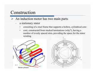
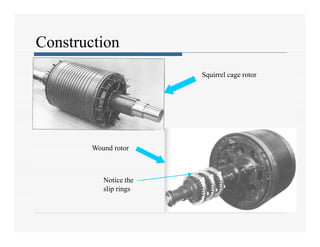
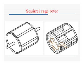
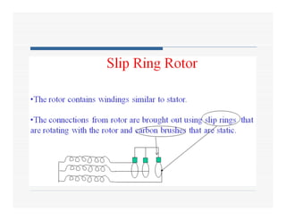
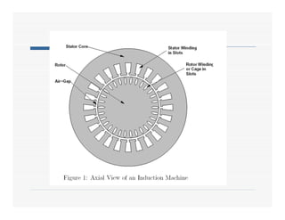
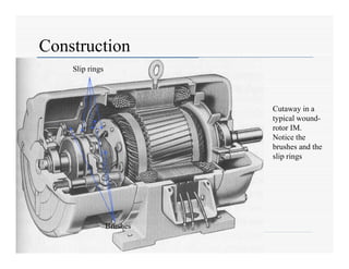
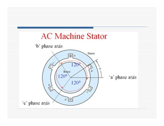
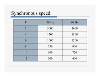
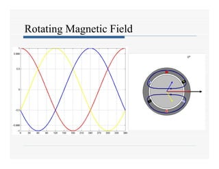
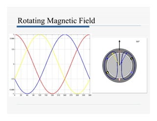
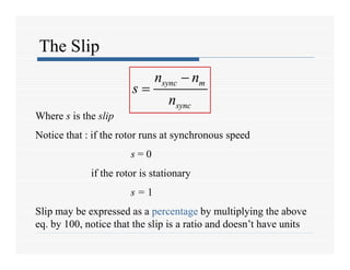
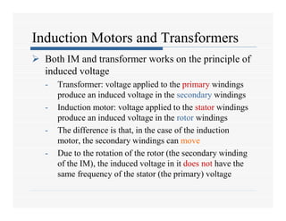
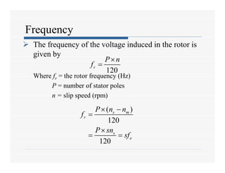
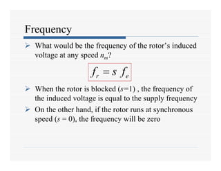
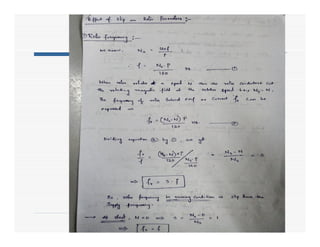
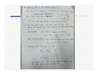
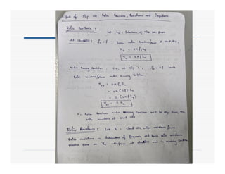
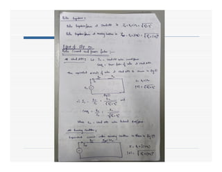
Induction Motors
Introduction
 Three-phase induction motors are the most
common and frequently encountered machines in
industry
- simple design, rugged, low-price, easy maintenance
- wide range of power ratings: fractional horsepower to 10 MW
- run essentially as constant speed from no-load to full load
- Its speed depends on the frequency of the power source
- not easy to have variable speed control
- Speed is determined by the supply frequency
- To vary its speed need a variable frequency supply
Construction
 An induction motor has two main parts
- a stationary stator
• consisting of a steel frame that supports a hollow, cylindrical core
• core, constructed from stacked laminations (why?), having a
number of evenly spaced slots, providing the space for the stator
winding
Construction
- a revolving rotor
• composed of punched laminations, stacked to create a series of rotor
slots, providing space for the rotor winding
• one of two types of rotor windings
• conventional 3-phase windings made of insulated wire (wound-rotor) »
similar to the winding on the stator
• aluminum bus bars shorted together at the ends by two aluminum rings,
forming a squirrel-cage shaped circuit (squirrel-cage)
 Two basic design types depending on the rotor design
- squirrel-cage: conducting bars laid into slots and shorted at both
ends by shorting rings.
- wound-rotor: complete set of three-phase windings exactly as the
stator. Usually Y-connected, the ends of the three rotor wires are
connected to 3 slip rings on the rotor shaft. In this way, the rotor
circuit is accessible.
Construction
Squirrel cage rotor
Wound rotor
Notice the
slip rings
Squirrel cage rotor
Construction
Cutaway in a
typical wound-
rotor IM.
Notice the
brushes and the
slip rings
Brushes
Slip rings
Rotating Magnetic Field
 Balanced three phase windings, i.e. mechanically displaced 120
degrees from each other, fed by balanced three phase source
 A rotating magnetic field with constant magnitude is produced,
rotating with a speed
Where fe is the supply frequency and
P is the no. of poles and nsync is called the synchronous speed in
rpm (revolutions per minute)
120 e
sync
f
n rpm
P

120 e
sync
f
n rpm
P

Synchronous speed
P 50 Hz 60 Hz
2 3000 3600
4 1500 1800
6 1000 1200
8 750 900
10 600 720
12 500 600
Rotating Magnetic Field
Principle of operation
 This rotating magnetic field cuts the rotor windings and
produces an induced voltage in the rotor windings
 Due to the fact that the rotor windings are short circuited, for
both squirrel cage and wound-rotor, and induced current
flows in the rotor windings
 The rotor current produces another magnetic field
 A torque is produced as a result of the interaction of those
two magnetic fields
Where ind is the induced torque and BR and BS are the magnetic
flux densities of the rotor and the stator respectively
ind R s
kB B
  
Induction motor speed
 At what speed will the IM run?
- Can the IM run at the synchronous speed, why?
- If rotor runs at the synchronous speed, which is the
same speed of the rotating magnetic field, then the rotor
will appear stationary to the rotating magnetic field and
the rotating magnetic field will not cut the rotor. So, no
induced current will flow in the rotor and no rotor
magnetic flux will be produced so no torque is
generated and the rotor speed will fall below the
synchronous speed
- When the speed falls, the rotating magnetic field will
cut the rotor windings and a torque is produced
Induction motor speed
 So, the IM will always run at a speed lower than
the synchronous speed
 The difference between the motor speed and the
synchronous speed is called the Slip
Where nslip= slip speed
nsync= speed of the magnetic field
nm = mechanical shaft speed of the motor
slip sync m
n n n
 
slip sync m
n n n
 
The Slip
sync m
sync
n n
s
n

 sync m
sync
n n
s
n


Where s is the slip
Notice that : if the rotor runs at synchronous speed
s = 0
if the rotor is stationary
s = 1
Slip may be expressed as a percentage by multiplying the above
eq. by 100, notice that the slip is a ratio and doesn’t have units
Induction Motors and Transformers
 Both IM and transformer works on the principle of
induced voltage
- Transformer: voltage applied to the primary windings
produce an induced voltage in the secondary windings
- Induction motor: voltage applied to the stator windings
produce an induced voltage in the rotor windings
- The difference is that, in the case of the induction
motor, the secondary windings can move
- Due to the rotation of the rotor (the secondary winding
of the IM), the induced voltage in it does not have the
same frequency of the stator (the primary) voltage
Frequency
 The frequency of the voltage induced in the rotor is
given by
Where fr = the rotor frequency (Hz)
P = number of stator poles
n = slip speed (rpm)
120
r
P n
f


( )
120
120
s m
r
s
e
P n n
f
P sn
sf
 


 
Frequency
 What would be the frequency of the rotor’s induced
voltage at any speed nm?
 When the rotor is blocked (s=1) , the frequency of
the induced voltage is equal to the supply frequency
 On the other hand, if the rotor runs at synchronous
speed (s = 0), the frequency will be zero
r e
f s f

r e
f s f

Induction Motors fundamentals PPT Notes.pdf

Induction Motors fundamentals PPT Notes.pdf

  • 1.
  • 2.
    Introduction  Three-phase inductionmotors are the most common and frequently encountered machines in industry - simple design, rugged, low-price, easy maintenance - wide range of power ratings: fractional horsepower to 10 MW - run essentially as constant speed from no-load to full load - Its speed depends on the frequency of the power source - not easy to have variable speed control - Speed is determined by the supply frequency - To vary its speed need a variable frequency supply
  • 3.
    Construction  An inductionmotor has two main parts - a stationary stator • consisting of a steel frame that supports a hollow, cylindrical core • core, constructed from stacked laminations (why?), having a number of evenly spaced slots, providing the space for the stator winding
  • 4.
    Construction - a revolvingrotor • composed of punched laminations, stacked to create a series of rotor slots, providing space for the rotor winding • one of two types of rotor windings • conventional 3-phase windings made of insulated wire (wound-rotor) » similar to the winding on the stator • aluminum bus bars shorted together at the ends by two aluminum rings, forming a squirrel-cage shaped circuit (squirrel-cage)  Two basic design types depending on the rotor design - squirrel-cage: conducting bars laid into slots and shorted at both ends by shorting rings. - wound-rotor: complete set of three-phase windings exactly as the stator. Usually Y-connected, the ends of the three rotor wires are connected to 3 slip rings on the rotor shaft. In this way, the rotor circuit is accessible.
  • 5.
    Construction Squirrel cage rotor Woundrotor Notice the slip rings
  • 6.
  • 9.
    Construction Cutaway in a typicalwound- rotor IM. Notice the brushes and the slip rings Brushes Slip rings
  • 10.
    Rotating Magnetic Field Balanced three phase windings, i.e. mechanically displaced 120 degrees from each other, fed by balanced three phase source  A rotating magnetic field with constant magnitude is produced, rotating with a speed Where fe is the supply frequency and P is the no. of poles and nsync is called the synchronous speed in rpm (revolutions per minute) 120 e sync f n rpm P  120 e sync f n rpm P 
  • 12.
    Synchronous speed P 50Hz 60 Hz 2 3000 3600 4 1500 1800 6 1000 1200 8 750 900 10 600 720 12 500 600
  • 13.
  • 14.
  • 15.
    Principle of operation This rotating magnetic field cuts the rotor windings and produces an induced voltage in the rotor windings  Due to the fact that the rotor windings are short circuited, for both squirrel cage and wound-rotor, and induced current flows in the rotor windings  The rotor current produces another magnetic field  A torque is produced as a result of the interaction of those two magnetic fields Where ind is the induced torque and BR and BS are the magnetic flux densities of the rotor and the stator respectively ind R s kB B   
  • 16.
    Induction motor speed At what speed will the IM run? - Can the IM run at the synchronous speed, why? - If rotor runs at the synchronous speed, which is the same speed of the rotating magnetic field, then the rotor will appear stationary to the rotating magnetic field and the rotating magnetic field will not cut the rotor. So, no induced current will flow in the rotor and no rotor magnetic flux will be produced so no torque is generated and the rotor speed will fall below the synchronous speed - When the speed falls, the rotating magnetic field will cut the rotor windings and a torque is produced
  • 17.
    Induction motor speed So, the IM will always run at a speed lower than the synchronous speed  The difference between the motor speed and the synchronous speed is called the Slip Where nslip= slip speed nsync= speed of the magnetic field nm = mechanical shaft speed of the motor slip sync m n n n   slip sync m n n n  
  • 18.
    The Slip sync m sync nn s n   sync m sync n n s n   Where s is the slip Notice that : if the rotor runs at synchronous speed s = 0 if the rotor is stationary s = 1 Slip may be expressed as a percentage by multiplying the above eq. by 100, notice that the slip is a ratio and doesn’t have units
  • 19.
    Induction Motors andTransformers  Both IM and transformer works on the principle of induced voltage - Transformer: voltage applied to the primary windings produce an induced voltage in the secondary windings - Induction motor: voltage applied to the stator windings produce an induced voltage in the rotor windings - The difference is that, in the case of the induction motor, the secondary windings can move - Due to the rotation of the rotor (the secondary winding of the IM), the induced voltage in it does not have the same frequency of the stator (the primary) voltage
  • 20.
    Frequency  The frequencyof the voltage induced in the rotor is given by Where fr = the rotor frequency (Hz) P = number of stator poles n = slip speed (rpm) 120 r P n f   ( ) 120 120 s m r s e P n n f P sn sf      
  • 21.
    Frequency  What wouldbe the frequency of the rotor’s induced voltage at any speed nm?  When the rotor is blocked (s=1) , the frequency of the induced voltage is equal to the supply frequency  On the other hand, if the rotor runs at synchronous speed (s = 0), the frequency will be zero r e f s f  r e f s f 