Downloaded 424 times


![Department of Mechanical Engineering, University Of Petroleum & Energy Studies, Dehradun
33
PORTC=0b00000101;
lcd_cmd(0x01);
lcd_string("REVERSE");
_delay_ms(200);
}
}
return 0;
}
void lcd_init()
{
lcd_cmd(0x02); // Home Postition
lcd_cmd(0x28); // Scroll display 1 char right
lcd_cmd(0x06); // Direction towards right. 0x04 is used for left
lcd_cmd(0x0C);
}
void lcd_string(char*str) // definig string to be displayed
{
int i=0;
while (str[i]!='0')
{](https://image.slidesharecdn.com/accelerometercontrolledrobot-140623131230-phpapp02/85/Accelerometer-controlled-robot-33-320.jpg)
![Department of Mechanical Engineering, University Of Petroleum & Energy Studies, Dehradun
34
lcd_data(str[i]); //for 8 bit mode
i++ ;
}
}
void digicount(unsigned int x)
{
lcd_cmd(0x04);
unsigned int i;
while(x!=0)
{
i=x%10;
lcd_data(i+48);
x=x/10;
}
lcd_cmd(0x06);
}
void adc_init()
{
ADMUX=(1<<REFS0)|(1<<REFS1);
ADCSRA=(1<<ADEN)|(1<<ADPS2)|(1<<ADPS1)|(1<<ADPS0);
}
int adc_read(unsigned char ch)
{
ch=ch&0b00000111;
ADMUX=0x40|ch;
ADCSRA|=(1<<ADSC);](https://image.slidesharecdn.com/accelerometercontrolledrobot-140623131230-phpapp02/85/Accelerometer-controlled-robot-34-320.jpg)

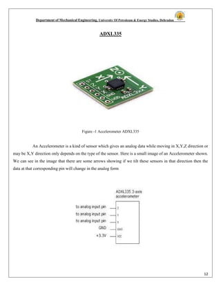
This document describes a project on an accelerometer controlled robot created by five students at the University of Petroleum and Energy Studies. It includes a certificate signed by their supervisor, Dr. Atul Sidola, acknowledging their work on the project. The introduction describes the goal of designing a low-cost robot that can be controlled by hand gestures detected by an accelerometer without the need for complex and expensive remote controls. It then provides details about the three main components of the robot: the accelerometer sensor, microcontroller for processing sensor output and controlling motors, and DC motors. The literature review provides background information on accelerometers, including how they work and common types such as capacitive and piezoelectric models.