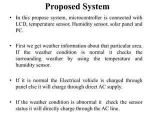
This document presents an electric vehicle charging method for smart homes/buildings with a photovoltaic system. It introduces an algorithm to determine optimal charging schedules for EVs based on predicted PV output and electricity consumption. It also discusses a prototype home energy management system application that provides EV charging schedules according to user preferences. The paper consists of describing the EV charging scheduling algorithm and implementation of the home EMS prototype application.
Design and Construction of Automatic Dual-Axis Solar Tracking System Using Li...Mahfuza Mansura
Solar energy is most promising green energy resource.. This project was done to increase the power produced by solar PV Cells by developing a advance dual-axis solar tracking system.
Automatic solar tracker is a system which helps to boost the energy production of solar panel. The whole system even does not need any external power source,
Wide area monitoring systems (WAMS) are essentially based on the new data acquisition technology of phasor measurement and allow monitoring transmission system conditions over large areas in view of detecting and further counteracting grid instabilities.
Mr. C.S.Satheesh, M.E.,
Servomotor
Control motors
Two Phase AC Servo Motor
Three Phase AC Servo Motor
DC Servo Motor
AC Servo Motor
Control Type Synchro.
Torque Transmission Type Synchro
Synchros
The electric power supplied by a photovoltaic power generation system depends on the solar radiation and temperature. Designing efficient PV systems heavily emphasizes to track the maximum power operating point.
This work develops a three-point weight comparison method that avoids the oscillation problem of the perturbation and observation algorithm which is often employed to track the maximum power point. Furthermore, a low cost control unit is developed, based on a single chip to adjust the output voltage of the solar cell array.
The development of a harmonized pan-European charging infrastructure for Elec...Roger Atkins
The development of a harmonized pan-European charging infrastructure for Electric Vehicles: Policy- Initiative interaction between EU and Member States
MAGDA COLLADO
Military objects treated before their exhibition at the Indiana War Memorial, 14th National, 1st Artillery, 21st Regiment guidon, 3rd National and the 80th National Civil War flags plus Japanese WWII & an Occupied France pocket map
A Hand Weaving Draft Portfolio to illustrate how fibers are interwoven to create fabric, that can be created with computer dobby looms in light industry in smaller shops for industrial applications.
Questions answered about Textile Conservation and the need for education. What can collectors and curators do to preserve textiles(or historic objects) more effectively?
Why do you continue to work in this field if you know you cannot "catch up" with the demand?
Wireless monitoring and control for smart grid and home appliancesUmayal Saravana Selvan
Secure and efficient communication between human being and managed devices are critical for smart grid and smart home. The power monitoring and controlling is playing a significant role in this project. In this project we proposes a new idea. The power consumption and their tariff amount will be automatically shown in the LCD display. This information will be automatically received to electricity board by using the Zigbee modem. From home we will pay the amount by using smart card system. If the amount is not paid within
the dead time the proposed system will automatically trip power supply from the EB station itself. When the amount is paid electricity board will enable the power supply again automatically.
Lecture Outline
Introduction to subject
Application Areas
Power Electronic Devices
Power Converters
What is power electronics?
1) Definition
Power Electronics: is the electronics applied to conversion and control of electric power.
Prerequisites
Power electronics incorporates concepts from the fields of
Analog circuits
Electronic devices
Control systems
Power systems
Magnetics
Electric machines
Numerical simulation
Scope
It is not possible to build practical computers, cell phones, personal data devices, cars, airplanes, industrial processes, and other everyday products without power electronics.
Alternative energy systems such as wind generators, solar power, fuel cells, and others require power electronics to function.
Technology advances such as electric and hybrid vehicles, laptop computers, microwave ovens, flat-panel displays, LED lighting, and hundreds of other innovations were not possible until advances in power electronics enabled their implementation.
Although no one can predict the future, it is certain that power electronics will be at the heart of fundamental energy innovations.
Applications: Electric VehicleTesla Model S
Functions of the power electronics:
1. Convert the DC battery voltage to the variable AC required to drive the AC motor
240 V battery
Variable-frequency, variable-voltage AC drives the motor
AC motor propels the rear axle
Up to 330 kW (acceleration)
Up to 60 kW regenerative braking
2. Control charging of the battery
Interface to 240 V 60 Hz 1φ 100 A circuit in garage.
Control AC current waveform to be sinusoidal, unity power factor.
Control charging of battery to maximize life.
Applications: Hybrid VehiclesPrius
Power Electronics Module:
Convert the DC battery voltage to the variable AC required to drive the AC motor.
Includes dc-dc boost converter and dc-3φ ac inverter
Control system can operate in all-electric mode or in hybrid gas+electric mode
Partial-power electronics
Parameter controlling of boiler in power plants using fuzzy logic controllereSAT Journals
Abstract Boilers are used industrially both for electric power generation and for supplying process stream in thermal power plants and its control is very important in many field applications. In some situation conventional PID control technique is being used for control purpose. These conventional controllers are not well suitable for some unusual conditions like load disturbances. Fuzzy logic control technique is being used to overcome these problems. A closed loop control system incorporating fuzzy logic has been developed for a class of industrial control systems. A unique fuzzy logic controller (FLC) structured with an efficient realization and a small rule base that can be easily implemented in existing industrial controllers. Fuzzy logic control system is much closer to human thinking and natural language than traditional control systems. This paper describes a fuzzy control technique and its implementation in boiler controls. Here a PIC microcontroller is being used where fuzzy control algorithm is implemented. Keywords: Fuzzy logic control, fuzzy logic controller, boiler controls, PIC microcontroller
Intelligent Street light monitoring systemvikas mantri
INTELLIGENT STREET LIGHTING
Home/INTELLIGENT STREET LIGHTING
Every evening, an intelligent street lighting control system has to light up at the right time and function seamlessly. A city’s street lights provide safer traffic conditions, safer pedestrian environment and can represent a great improvement to the city’s architectural, touristic and commercial output. These benefits are not exactly cheap though, with an average of 40% of the public budgets’ energy bill being spent for street lighting alone. The increasing energy price, plus the significant maintenance costs and always increasing expectations manifested by the public put a continuous pressure on the lighting budgets.
inteliLIGHT® is a remote street lighting control solution that offers you detailed, lamp-level management capabilities of every street light in your city and ensures that the right amount of light is provided where and when needed. Equally important, in-depth grid management gives an accurate real-time feedback of any change occurring along the grid, reduces both energy loss and energy surges and offers advanced maintenance optimization tools. Using the existing infrastructure, you can have live detailed information over the grid and transform the existing distribution level network into an intelligent infrastructure of the future
IJRET : International Journal of Research in Engineering and Technology is an international peer reviewed, online journal published by eSAT Publishing House for the enhancement of research in various disciplines of Engineering and Technology. The aim and scope of the journal is to provide an academic medium and an important reference for the advancement and dissemination of research results that support high-level learning, teaching and research in the fields of Engineering and Technology. We bring together Scientists, Academician, Field Engineers, Scholars and Students of related fields of Engineering and Technology.
Photovoltaic Management System in Residential Areas Using Power Line Communic...IJTET Journal
Abstract— Energy consumption in residential areas is rising; residential areas have deployed a photovoltaic (PV) system to save
energy cost and provide continuous power in the area. The PV system needs to be continuously monitored to maintain its performance.
In addition, it is desirable to monitor each PV module because one abnormal PV module affects the whole PV system. Here Power line
communication (PLCC) technology is used to monitor each PV module in order to check the performance of PV system. Power line
communication (PLCC) carries data on a conductor that is also used simultaneously for AC electric power transmission. The
parameters in PV module are monitored by PLC. The system architecture is composed of the following components: PLC modem,
CUK Converter, and inverter connected with AC load. The PLC modems are deployed on each PV module for continuous monitoring.
The CUK converter will provide constant voltage to the battery. The device retrieves the stored data in microcontroller unit and
informs users about the status of the photovoltaic module. The device retrieves the stored data from the converter to inform users of
the status of the PV system. Voltage, Current and Temperature are the parameters which are going to be noted in PV module. The
output of the inverter circuit is given to the AC load by using resistive load. Users can browse and figure out the PV system
performance in detail by using power line communication technology. The system is installed in the field.It is composed of sixteen PV
modules with 960V; since each PV module provides 60V and a 1kW inverter. This scheme will maintain the performance of a PV
system and can be used for industrial applications.
DC MOTOR SPEED CONTROL USING ON-OFF CONTROLLER BY PIC16F877A MICROCONTROLLERTridib Bose
This presentation consists the speed control of a dc motor using hardware (microcontroller) by changing the reference voltages logically and minimising errors.
MONTHLY ELECTRICITY BILLING WITH BILL SMS USING PIC.pptxNANDHAKUMARA10
The project provides a system that allows for consumed electricity reading in unit and How much amount of Current Can be Consumed by User its Prevent the Electricity Theft.
Our system provides the electricity readings on an LCD screen as well as can SMS this reading and cost to the user.
This lets the user know about his exact electricity units consumed and cost directly from his meter so that there is no chance of bill tampering.
The project allows a two way reading. One on LCD display and the second on SMS. Our project consists of IOT connected to a ATMEGA328p is an family of PIC. The system continuously monitors electrical pulses and calculates the unit consumption.
Accelerate your Kubernetes clusters with Varnish CachingThijs Feryn
A presentation about the usage and availability of Varnish on Kubernetes. This talk explores the capabilities of Varnish caching and shows how to use the Varnish Helm chart to deploy it to Kubernetes.
This presentation was delivered at K8SUG Singapore. See https://feryn.eu/presentations/accelerate-your-kubernetes-clusters-with-varnish-caching-k8sug-singapore-28-2024 for more details.
JMeter webinar - integration with InfluxDB and GrafanaRTTS
Watch this recorded webinar about real-time monitoring of application performance. See how to integrate Apache JMeter, the open-source leader in performance testing, with InfluxDB, the open-source time-series database, and Grafana, the open-source analytics and visualization application.
In this webinar, we will review the benefits of leveraging InfluxDB and Grafana when executing load tests and demonstrate how these tools are used to visualize performance metrics.
Length: 30 minutes
Session Overview
-------------------------------------------
During this webinar, we will cover the following topics while demonstrating the integrations of JMeter, InfluxDB and Grafana:
- What out-of-the-box solutions are available for real-time monitoring JMeter tests?
- What are the benefits of integrating InfluxDB and Grafana into the load testing stack?
- Which features are provided by Grafana?
- Demonstration of InfluxDB and Grafana using a practice web application
To view the webinar recording, go to:
https://www.rttsweb.com/jmeter-integration-webinar
Key Trends Shaping the Future of Infrastructure.pdfCheryl Hung
Keynote at DIGIT West Expo, Glasgow on 29 May 2024.
Cheryl Hung, ochery.com
Sr Director, Infrastructure Ecosystem, Arm.
The key trends across hardware, cloud and open-source; exploring how these areas are likely to mature and develop over the short and long-term, and then considering how organisations can position themselves to adapt and thrive.
GraphRAG is All You need? LLM & Knowledge GraphGuy Korland
Guy Korland, CEO and Co-founder of FalkorDB, will review two articles on the integration of language models with knowledge graphs.
1. Unifying Large Language Models and Knowledge Graphs: A Roadmap.
https://arxiv.org/abs/2306.08302
2. Microsoft Research's GraphRAG paper and a review paper on various uses of knowledge graphs:
https://www.microsoft.com/en-us/research/blog/graphrag-unlocking-llm-discovery-on-narrative-private-data/
Generating a custom Ruby SDK for your web service or Rails API using Smithyg2nightmarescribd
Have you ever wanted a Ruby client API to communicate with your web service? Smithy is a protocol-agnostic language for defining services and SDKs. Smithy Ruby is an implementation of Smithy that generates a Ruby SDK using a Smithy model. In this talk, we will explore Smithy and Smithy Ruby to learn how to generate custom feature-rich SDKs that can communicate with any web service, such as a Rails JSON API.
Neuro-symbolic is not enough, we need neuro-*semantic*Frank van Harmelen
Neuro-symbolic (NeSy) AI is on the rise. However, simply machine learning on just any symbolic structure is not sufficient to really harvest the gains of NeSy. These will only be gained when the symbolic structures have an actual semantics. I give an operational definition of semantics as “predictable inference”.
All of this illustrated with link prediction over knowledge graphs, but the argument is general.
Encryption in Microsoft 365 - ExpertsLive Netherlands 2024Albert Hoitingh
In this session I delve into the encryption technology used in Microsoft 365 and Microsoft Purview. Including the concepts of Customer Key and Double Key Encryption.
Software Delivery At the Speed of AI: Inflectra Invests In AI-Powered QualityInflectra
In this insightful webinar, Inflectra explores how artificial intelligence (AI) is transforming software development and testing. Discover how AI-powered tools are revolutionizing every stage of the software development lifecycle (SDLC), from design and prototyping to testing, deployment, and monitoring.
Learn about:
• The Future of Testing: How AI is shifting testing towards verification, analysis, and higher-level skills, while reducing repetitive tasks.
• Test Automation: How AI-powered test case generation, optimization, and self-healing tests are making testing more efficient and effective.
• Visual Testing: Explore the emerging capabilities of AI in visual testing and how it's set to revolutionize UI verification.
• Inflectra's AI Solutions: See demonstrations of Inflectra's cutting-edge AI tools like the ChatGPT plugin and Azure Open AI platform, designed to streamline your testing process.
Whether you're a developer, tester, or QA professional, this webinar will give you valuable insights into how AI is shaping the future of software delivery.
UiPath Test Automation using UiPath Test Suite series, part 4DianaGray10
Welcome to UiPath Test Automation using UiPath Test Suite series part 4. In this session, we will cover Test Manager overview along with SAP heatmap.
The UiPath Test Manager overview with SAP heatmap webinar offers a concise yet comprehensive exploration of the role of a Test Manager within SAP environments, coupled with the utilization of heatmaps for effective testing strategies.
Participants will gain insights into the responsibilities, challenges, and best practices associated with test management in SAP projects. Additionally, the webinar delves into the significance of heatmaps as a visual aid for identifying testing priorities, areas of risk, and resource allocation within SAP landscapes. Through this session, attendees can expect to enhance their understanding of test management principles while learning practical approaches to optimize testing processes in SAP environments using heatmap visualization techniques
What will you get from this session?
1. Insights into SAP testing best practices
2. Heatmap utilization for testing
3. Optimization of testing processes
4. Demo
Topics covered:
Execution from the test manager
Orchestrator execution result
Defect reporting
SAP heatmap example with demo
Speaker:
Deepak Rai, Automation Practice Lead, Boundaryless Group and UiPath MVP
Securing your Kubernetes cluster_ a step-by-step guide to success !KatiaHIMEUR1
Today, after several years of existence, an extremely active community and an ultra-dynamic ecosystem, Kubernetes has established itself as the de facto standard in container orchestration. Thanks to a wide range of managed services, it has never been so easy to set up a ready-to-use Kubernetes cluster.
However, this ease of use means that the subject of security in Kubernetes is often left for later, or even neglected. This exposes companies to significant risks.
In this talk, I'll show you step-by-step how to secure your Kubernetes cluster for greater peace of mind and reliability.
Essentials of Automations: Optimizing FME Workflows with ParametersSafe Software
Are you looking to streamline your workflows and boost your projects’ efficiency? Do you find yourself searching for ways to add flexibility and control over your FME workflows? If so, you’re in the right place.
Join us for an insightful dive into the world of FME parameters, a critical element in optimizing workflow efficiency. This webinar marks the beginning of our three-part “Essentials of Automation” series. This first webinar is designed to equip you with the knowledge and skills to utilize parameters effectively: enhancing the flexibility, maintainability, and user control of your FME projects.
Here’s what you’ll gain:
- Essentials of FME Parameters: Understand the pivotal role of parameters, including Reader/Writer, Transformer, User, and FME Flow categories. Discover how they are the key to unlocking automation and optimization within your workflows.
- Practical Applications in FME Form: Delve into key user parameter types including choice, connections, and file URLs. Allow users to control how a workflow runs, making your workflows more reusable. Learn to import values and deliver the best user experience for your workflows while enhancing accuracy.
- Optimization Strategies in FME Flow: Explore the creation and strategic deployment of parameters in FME Flow, including the use of deployment and geometry parameters, to maximize workflow efficiency.
- Pro Tips for Success: Gain insights on parameterizing connections and leveraging new features like Conditional Visibility for clarity and simplicity.
We’ll wrap up with a glimpse into future webinars, followed by a Q&A session to address your specific questions surrounding this topic.
Don’t miss this opportunity to elevate your FME expertise and drive your projects to new heights of efficiency.
Essentials of Automations: Optimizing FME Workflows with Parameters
Electric Vehicle Charging Method for SmartHomes/Buildings with a Photovoltaic System
1. Electric Vehicle Charging Method
for Smart
Homes/Buildings with a
Photovoltaic System
Manjit Singh(U10EE719)
Subash Kumar(U10EE026)
Prabhat Ranjan(U10EE020)
2. Abstract
• Due to the increased penetration of electric vehicles (EVs) and photovoltaic
(PV) systems, additional application for home/building energy management
system (EMS) is needed to determine when and how much to charge an
electric vehicle in an individual home/building.
• This paper presents a smart EV charging method for smart homes/buildings
with a PV system. The paper consists of two parts: EV charging scheduling
algorithm for smart homes/buildings and implementation of prototype
application for home/building EMS.
• The proposed EV charging algorithm is designed to determine the optimal
schedules of EV charging based on predicted PV output and electricity
consumption.
• The implemented prototype application for home/building EMS can
provide EV charging schedules according to user preferences
3. Introduction
• Due to the increased penetration of electric vehicles (EVs) and
photovoltaic (PV) systems, additional application for home/building
energy management system (EMS) is needed to determine when and
how much to charge an electric vehicle in an individual home/building.
This paper presents a smart EV charging method for smart
homes/buildings with a PV system.
• The proposed EV charging algorithm is designed to determine the
optimal schedules of EV charging based on predicted PV output and
electricity consumption.
• The implemented prototype application for home/building EMS can
provide EV charging schedules according to user preferences.
4. Existing System
• There is no existing method is available for smart electrical
vehicle charging.
• Thus the way we go for the proposed system. In this we
desired one efficient alternating method for smart charging.
5. Scope of the project
• The main objective of this project is charge the electric
vehicle battery using AC power supply or solar panel
depend upon the weather condition.
• If the weather is normal Electrical vehicle is charged
through panel else it will charge through direct AC supply.
6. Proposed System
• In this propose system, microcontroller is connected with
LCD, temperature sensor, Humidity sensor, solar panel and
PC.
• First we get weather information about that particular area.
If the weather condition is normal it checks the
surrounding weather by using the temperature and
humidity sensor.
• If it is normal the Electrical vehicle is charged through
panel else it will charge through direct AC supply.
• If the weather condition is abnormal it check the sensor
status it will directly charge through the AC line.
8. Number of Units (Modules)
•
•
•
•
•
•
Power supply unit
Microcontroller unit
Communication unit
Device driver unit
Display unit
Sensor unit
9. Power supply unit
• The supply of 5V DC is given to the system which is converted
from 230V AC supply. Firstly, the step down transformer will
be used here for converting the 230V AC into 12V AC.
• The microcontroller will support only the DC supply, so the AC
supply will be converted into DC using the bridge rectifier.
• The output from the filter is given to the 7805 voltage regulator
which will convert the 12V DC into 5V DC.
• So the pure 5V DC is getting as the output from the power
supply unit
10. Microcontroller unit
PIC microcontroller:
• In this project the Pic microcontroller is used in the Home
section.
• In this we use pic microcontroller with sensor network here
we using Temperature sensor is used to monitor the inside
and outside room temperature.
• Depends upon the temperature we will control the fan or AC
in the home section.
• This whole status is displayed in the LCD monitor
11. Communication unit
MAX232:
• MAX232 is used to convert the voltage level,
which is compatible for the PC for receive and
storing the information from the cars.
12. Device Driver Unit
Device Driver Unit
• Relay:
The relay is used to control the supply to the electrical device depend upon
environment temperature.
Display unit
• LCD:
The LCD is used to display the information received in the Zigbee
transceiver. The Temperature of the environment also displayed on LCD.
13. Sensor unit
•
Temperature sensor:
The temperature sensor is used to monitor the surrounding
temperature.
•
HUMIDITY SENSOR:
The humidity sensor is used to sense the environment humidity
condition.
14. Given Input and Expected output
Power Supply Unit:
• In the power supply unit the 230V AC is converted into 5V DC.
Given Input:
•
230V AC supply is given as the input to the power supply unit.
Expected Output:
•
The 5V DC supply is getting as the output from the power
supply unit.
15. Microcontroller Unit
Microcontroller Unit:
Microcontroller unit controls the devices connected with this (Max232, relay
with the motor, and LCD).
PIC Microcontroller:
Given Input:
Inputs to the controller is temperature sensor output that is surrounding
temperature and humidity.
This sensor output analog values, this values are convert into digital using
analog to digital converter and we get the Digital value corresponding to the
sensor value.
Expected Output:
Relay with DC motor, LCD these are the output devices used in this project.
DC motors are act as a load .The LCD is used to display the status of the
system.
16. Communication Unit:
Communication Unit:
Communication devices send or receive the data’s in wire/wireless to the
other section.
MAX232:
• Given Input:
The max232 is used in collecting center. The information received by
the Zigbee transmitter is given to the max232 via serial port of the processor
in binary format.
•
Expected Output:
The output of max232 is coming from receive pin as 0’s and 1’s which
will be the input for PC for uploading the data.
17. Display Unit
LCD is used as the display unit in this project.
LCD:
Given Input:
The 5V DC supply is given as the input for LCD. In contains the 3 command
lines and 8 data lines. These 11 lines will be connected with the
microcontroller.
The commands and datas will be given as the hexadecimal format from the
microcontroller.
Expected Output:
The data from the command lines will initialize the LCD. The data from the
data lines will be displayed in the LCD.
18. Relay Unit
Relay and battery
In this project the battery is load and which is connected with
the relay unit.
Given Input:
The 12V DC supply is given as the input to the coil of the relay.
5V DC is given as the triggering input to the transistor for switching
purpose.
It contains two terminals, they are normally open, normally closed.
Expected Output:
After giving the input for the relay, the coil gets magnetize and the
magnetic tip will be moved from normally closed to normally open
depend upon the sensor value.
The battery charging using the relay from either Solar or AC power
supply.
20. Circuit Diagram Explanation
• In this fig shown the circuit diagram of electric vehicle charging method
for smart home/building with a PV system.
• In this circuit diagram used components are PIC µc, Temperature sensor,
humidity sensor, LCD Display, Relays, Power supply,MAX232 etc.
• Humidity & temperature sensor are connected to the PIC µc pin 2 & 3
respectively.
• LCD is connected in µc . Total 14 pins are available in LCD. Three
command pins, Eight data pins & 3 supply pins shown in fig.
• One relay is connected in direct AC line and another relay is connected in
solar panel.
• When the battery charge through the solar panel then LED ON gives green
light. When the battery charge through direct AC supply then the LED
OFF.
• MAX232 device connected in µc as well as PC (Personal Computer).Give
the command from the PC and check the Output through LCD.
21. Block diagram Description
•
•
•
•
•
•
•
•
•
•
•
•
•
•
•
Block 1:
Power Supply Unit.
Block 2:
PIC16F877A microcontroller unit.
Block 3:
Humidity sensor.
Block 4:
Relay driver.
Block 5:
Temperature sensor.
Block6:
Max 232.
Block7:
Battery
Block 8:
LCD.
22. Power Supply Unit
• The ac voltage, typically 220V, is connected to a
transformer, which steps that ac voltage down to the
level of the desired dc output.
• A diode rectifier then provides a full-wave rectified
voltage that is initially filtered by a simple capacitor
filter to produce a dc voltage.
• This resulting dc voltage usually has some ripple or ac
voltage variation.
24. Working principle
Transformer
The potential transformer will step down the power supply
voltage (0-230V) to (0-6V) level.
Then the secondary of the potential transformer will be
connected to the precision rectifier, which is constructed with
the help of op–amp.
The advantages of using precision rectifier are it will give peak
voltage output as DC; rest of the circuits will give only RMS
output.
Bridge rectifier
When four diodes are connected as shown in figure, the circuit
is called as bridge rectifier.
The input to the circuit is applied to the diagonally opposite
corners of the network, and the output is taken from the
remaining two corners.
25. PIC16F877A Microcontroller
Special Microcontroller Features
•
•
•
•
•
•
•
•
•
•
Flash Memory: 14.3 Kbytes (8192 words)
Data SRAM: 368 bytes
Data EEPROM: 256 bytes
Self-reprogrammable under software control
In-Circuit Serial Programming via two pins (5V)
Watchdog Timer with on-chip RC oscillator
Programmable code protection
Power-saving Sleep mode
Selectable oscillator options
In-Circuit Debug via two pins
27. Humidity sensor
Humidity is the presence of water in air. The amount of
water vapor in air can affect human comfort as well as
many manufacturing processes in industries.
The presence of water vapor also influences various
physical, chemical, and biological processes.
Humidity measurement in industries is critical because it
may affect the business cost of the product and the
health and safety of the personnel.
Hence, humidity sensing is very important, especially in
the control systems for industrial processes and human
comfort.
28. Relay driver
Driver circuit:
The ULN2003 is a monolithic high voltage and high current
Darlington transistor arrays.
Applications include relay drivers, hammer drivers, lamp drivers,
display drivers (LED gas discharge), line drivers, and logic buffers.
The ULN2003 has a 2.7kW series base resistor for each Darlington
pair for operation directly with TTL or 5V CMOS devices.
FEATURES
* 500mA rated collector current (Single output)
* High-voltage outputs: 50V
* Inputs compatible with various types of logic.
* Relay driver application
30. Temperature sensor
• Temperature is the most-measured process variable in industrial
automation. Most commonly, a temperature sensor is used to convert
temperature value to an electrical value.
• Temperature Sensors are the key to read temperatures correctly and to
control temperature in industrials applications.
• In the temperature functional module we developed, we use the
LM34 series of temperature sensors.
• The LM34 series are precision integrated-circuit temperature sensors,
whose output voltage is linearly proportional to the Fahrenheit
temperature.
31. Temperature sensor
• The LM34 does not require any external calibration or
trimming to provide typical accuracies of 1.2 F at room
temperature and 11.2 F over a full -50 to +300 F
temperature range.
• The LM34 is rated to operate over a -50 to +300 F
temperature range.
• The LM34 thus has an advantage over linear temperature
sensors calibrated in degrees Kelvin, as the user is not
required to subtract a large constant voltage from its output
to obtain convenient Fahrenheit scaling.
33. Max 232
•
The MAX232 is a dual driver/receiver that includes a capacitive
voltage generator to supply RS 232 voltage levels from a single 5v
supply. Each receiver converts RS-232 to 5v TTL/CMOS levels.
•
Each driver converts TLL/CMOS input levels into EIA-232 levels.
The P3_0 (RX) and P3_1 (TX) pin of controller is connected to the
max 232 driver and the TX and RX pin of max 232 is connected to the
GSM modem or PC.
35. Battery
Battery
• A battery, which is actually an electric cell, is a device that
produces electricity from a chemical reaction.
• When the cell is connected to an external load, or device to be
powered.
• The negative electrode supplies a current of electrons that flow
through the load and are accepted by the positive electrode.
• When the external load is removed the reaction ceases.
37. Software Requirements:
• Embedded c
• MPLab Compiler or CCS Compiler
• .net
Advantages:
• Energy consuming.
• Load balancing and monetary expense
reduction.
Applications:
To Reduce the Power consumption
• This system can be applied in home and
industry section to reduce the power consume.
38. Future Enhancement:
Further work is required for considering the effects of PV
output and electricity consumption forecast errors, and
vehicle-to-grid on the performance of the proposed
method.
39. Conclusion:
The EMS application is required to determine optimal EV charging
scheduling for smart homes/buildings with a PV system.
In this paper, a cost-effective EV charging method is proposed and
implemented for smart homes/buildings with a PV system.
The proposed smart EV charging algorithm for smart homes/buildings
consists of two stages: prediction of PV output and electricity
consumption, and EV charging scheduling.
40. Reference
[1] S. Han, S. Han, and K. Sezaki, “Estimation of achievable power
capacity from plug-in electric vehicles for V2G frequency regulation:
case studies for market participation,” IEEE Trans. Smart Grid, vol. 2,
no. 4, pp. 632-641, Dec. 2011.
[2] C.-K. Wen, J.-C. Chen, J.-H. Teng, and P. Ting, “Decentralized plugin electric vehicle charging selection algorithm in power systems,”
IEEETrans. Smart Grid, vol. 3, no. 4, pp. 1779-1798, Dec. 2012.
[3] N. Kushiro, S. Suzuki, M. Nakata, H. Takahara, and M.
Inoue,“Integrated residential gateway controller for home energy
managementsystem,” IEEE Trans. Consumer Electron., vol. 49, no. 3,
pp. 629-636,Aug. 2003.
[4] D.-M. Han and J.-H. Lim, “Design and implementation of smart home
energy management systems based on zigbee,” IEEE Trans. On
Consumer Electron., vol. 56, no. 3, pp. 1417-1425, Aug. 2010.