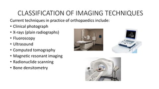
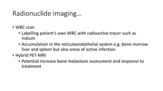
IMAGING TECHNIQUES
Presented by
Dr Binod Chaudhary
Department of Orthopaedics
WRH, PoAHS
Contents
• Introduction
• Historical perspective
• Classification of different types of imaging techniques
• General application of imaging in orthopaedics
• Conclusion
INTRODUCTION
• A veritable tool in the evaluation of surgical patients.
• Many surgical diagnoses can be made with clinical assessment.
However, radiological investigations remains vital to the diagnosis,
preparation and follow up of patients
• A myriad of imaging options are available.
• Initial application of radiography lay in the demonstration of fractures
and radio-opaque foreign bodies.
• Subsequent parallel development of Radiology and Orthopaedics had
broaden the scope.
• Today, high precision interventional therapeutic procedure can be
carried out.
HISTORICAL PERSPECTIVE
• Wilhelm Conrad Rontgen: discovered x-rays(1895). Nobel prize in
1901 (father of radiology).
• 1920: use of contrast for x ray studies
• 1950s: nuclear medicine was born
• 1970s: ultrasound came into use
• Sir Godfrey Hounsfield invented CT in 1975.
USES OF RADIOLOGICAL TECHNIQUES
• To aid diagnosis of a medical and/or surgical disorder
• To guide a surgical procedure
• Monitoring
• Interventional radiological techniques
CLASSIFICATION OF IMAGING TECHNIQUES
Current techniques in practice of orthopaedics include:
• Clinical photograph
• X-rays (plain radiographs)
• Fluoroscopy
• Ultrasound
• Computed tomography
• Magnetic resonant imaging
• Radionuclide scanning
• Bone densitometry
CLINICAL PHOTOGRAPH
• First line imaging
• For documentation and monitoring
• Uses
In trauma with soft tissue
involvement
In management of clubfoot pre-,
intra- and post correction
Angular deformities of the limb,
etc
X-RAYS (PLAIN RADIOGRAPHY)
Electromagnetic radiation
• Travel at speed of light ~3,00,000 km/s
• Not affected by electric or magnetic fields
• Travel through vaccum
X-RAYS (PLAIN RADIOGRAPHY)
Definition
• High energy radiation which undergo differential absorption by
tissues as they pass through the body
• Generated via interactions of the accelerated electrons with electrons
of tungsten nuclei within the tube anode.
• 2 types of x-rays generated: Characteristic radiation and
Bremsstrahlung radiation.
Characteristic Radiation Bremsstrahlung radiation
• Quantity of x-rays generated: directly proportional to number of
moving electrons.
• Quality of x-rays generated: proportional to the speed of the
electrons
• 2 outcomes when x-rays interacts with matter
1. Photoelectric absorption
2. Compton scattering
Basics of X-ray physics
• Travel in straight lines
• Body parts further away
from the detector are
magnified compared with
those that are closer and
vice versa.
• A source tat is too near the
patient will further
exaggerate the size of
structures nearest to that
sources.
Tissue densities
• an x-ray image is a map of x-
ray attenuation
• Attenuation of x-rays is
variable depending on
density and thickness of
tissues
• Describing x-ray
abnormalities in terms of
density may help in
determining the tissue
involved.
• The greatest contrast is
found in areas of greatest
difference in density of
adjacent structures.
Uses
• Invaluable investigation in orthopaedics
• Have wide application such as
Diagnosis
Planning of surgery
Intraoperative assessment of fixation of fractures
Monitoring of treatment and healing
Occasionally for interventions eg. Vertebroplasty, SNRB.
Advantages
• Cheap
• Easily available
• Good in assessing bone due to its high calcium content and intrinsic
contrast.
COMPUTED TOMOGRAPHY(CT) SCAN
• One of the major advances in radiology
in recent years.
• Uses a computer to create an image
from an integration of multiple xrays
exposures taken in a circle round the
patients.
• Heavy ionizing radiation dose.
• Attenuation: amount of x-rays absorbed by tissues
(different for different tissues)
• Hounsfield units describe the attenuation co-
efficient of tissues
• Bone=1000 Hu
• Water= 0 Hu
• Air= -1000 Hu
• There is a much wider range of attenuation co-
efficient than the greyscale a human eye can
perceive
• Different windows for different tissue types
allowing the whole range of attenuation to be
displayed and improves overall detail.
Advantages
• Reconstruction possible in any plane desired
• Good for surgical planning in complex fractures-
3D reconstruction
• Exellent resolution of cortical bone
• Better soft tissue attenuation than plain x-ray
• CT guided biopsy
• CT with contrast
Disadvantages
• Availability
• High resolution dose
• Claustrophobia
MRI
• Newest of the imaging techniques
• Does not use ionizing radiation
• Principle: body tissues consists of
protons/electrons. In a strong uniform
field such as MRI scanner, these nuclei
align themselves with the main magnetic
field.
A brief radiofrequency, pulse is applied
to alter the motion of the nuclei. When
removed, the nuclei realign with the
main magnetic field, emitting energy(RF
signal).
• T2 signal
• Time taken for the protons to loose
their coherence once radiofrequency
turned off
• Water rich tissues have longer T2 time
as they contain more protons
• Hence they release energy for a
longer time and give a high signal
• T1 signal
• Time taken for 63% of the protons to
return to the longitudinal spin axis
• Repitition time (TR) (msec)
• The time between repetition of pulses
• T2 images have very high TR time
• Otherwise the water dense tissues will not have released enough
energy to detect pulses are given frequency though, fat appears
white rather than water.
• Time to echo (TE) (msec)
• Time from when the pulse is stopped to when the signal is
measured.
• Differential sequences
• T1 weighted- short TR (TR<1000 ms), short TE(<60 ms)
fat=bright
fluid= dark
defining anatomy
• T2 weighted- long TR (TR>1000ms), long TE (TE>60 sec)
Fluid= bright
Defining pathology
• Proton density (PD)- long TR(TR>1000ms), short TE(TE<60ms)
• Part T1, Part T2
• Useful in certain situations e.g. the meniscus
• Contrast (Gadolinium)
• High net magnetic moment
• More strongly affects hydrogen
ions in close proximity to the
contrast.
• Enhances the image and results in
high signal on T1 scans as well.
• Shows pathologic fluid collections
better.
• Advantages
• No ionizing radiation
• High quality image
• Can be used with contrast
• Abscesses and intra-articular pathology
• Disadvantages
• Claustrophobia
• Noisy
• Not tolerated well by children
• Availability
• Contraindication to MRI e.g. aneurysm
clips and pace makers, internal hearing
aids,
• Metal artifacts: MARS sequence
• Over diagnosis of asymptomatic
ULTRASOUND
• Second most common method of
imaging
• Relies on high frequency sound waves
generated by a transducer containing
piezoelectric material
• Principle:
generated sound waves are
reflected by tissue interfaces and, by
ascertaining the direction and the time
taken for a pulse to return, it is possible
to form an image.
Acoustic impedance
• Impedance between tissues creates echo
• Minimal differences between fat and
muscle(most waves pass through)
• Large difference between air and
skin(most waves reflected-use gel)
• High impedance=bright
• Low impedance= dark
Advantages
• Non ionizing
• Cheap
• Portable
• Dynamic imaging
• Very good for cystic structures
• Biopsy, injection, aspiration
Disadvantages
• Highly operator dependent
• Only for superficial structures (cannot
penetrate cortical bone)
• Limited field of fiew
• Poor resolution comparatively
BONE SCAN(RADIONUCLIDE IMAGING)
• Gamma rays emitted from a radioactive isotope
of technetium 99 bound to a phosphate to give a
map of blood flow and osteoblastic activity
Technetium-99
• Unstable radioisotope
• Emits gamma rays
• Derived from the decay of molybdenum 99
• Short half life of 6 hours
• Excreted via kidney (bladder hydration and
Mechanism of action
• Technetium-99 is attached to methyl
diphosphonate(MDP) when injected iv
• The MDP interact with HA crystals in bone-
depending on adequate vascularity to the area
in question.
• Because HA crystals are generated by
osteoblasts mineralizing bone it is a direct
reflection of osteoblastic activity.
• The gamma rays emitted by the T-99 are dected
by a gamma camera
• A digital image is created giving a map of blood
flow and osteoblastic activity
Radionuclide imaging….
3 phases of triple bone scan
• Vascular phase (1-2min)
• Blood pool phase (3-5 min)
• Static phase(4 hrs)
Radionuclide imaging…
• Single photon emission computed tomography-CT (SPECT-CT)
• Gamma camera with CT component on the same scanner
• Multi-planar imaging
• Increasing resolution, decrease noise and increase localization
• Positron emission tomography-CT (PET-CT)
• Exploiting increase metabolic rato of tumors i.e glucose
consumption
• E.g deoxyglucose labelled 18 Fluorine (1/2 life-112 min)
Radionuclide imaging…
• WBC scan
• Labelling patient’s own WBC with radioactive tracer such as
indium
• Accumulation in the reticuloendothelial system e.g. bone marrow
liver and spleen but also areas of active infection
• Hybrid PET-MRI
• Potential increase bone metastasis assessment and response to
treatment
Useful for
• Tumors (metastatic and primary esp in spine)
• Infection-osteomyelitis
• Stress fractures
• Prosthetic loosening/pain
• Paget’s disease
Disadvantages
• Poor specificity although very sensitive
• Radiation dose is fairly high
• False negative in areas of low blood supply-e.g avascular bone, lytic
tumors
DEXA scan
• Dual energy x-ray absorbimetry
• Utilizes xrays of different energies
• Absorbed in different proportions by
bone and soft tissues
• Used to assess bone mineral density
Result interpretation
• Units of bone mineral density are g/cm3
• Values are related to the peak bone mass density of a young adult or
matched by age
• The T score represents comparison with peak BMD of a young adult
• The z score represents the age-matched score
• Sex and race are matched in both (only difference is age matching in
the Z score)
• The T score is used to determine whether there is osteoporosis
• The Z score is used to assess whether the reduced BMD is related to
another cause i.e lower than expected for age
WHO criteria for osteoporosis relies
on T score
• 0 to -1 =normal
• -1 to -2.5= osteopenia
• <-2.5 = osteoporosis
• <-2.5 +fragility fracture=severe
osteoporosis
Disadvantages
• No differentiation between cortical
and cancellous density
• Falsely high BMD in fractured
sclerotic vertebrae and degenerate
GENERAL APPLICATION OF IMAGING IN
ORTHOPAEDICS
General applications
• Diagnosis, classification and staging of diseases
• Preoperative planning and templating
• Intraoperative monitoring
• Therapeutic purposes
• Monitoring of treatment and healing process
Diagnosis
• Almost all the modalities are used to make or confirm diagnosis
• Plain radiography plays an invaluable role especially in trauma
• CT scan usuallu augments plain radiograph, though plays important
role in complex trauma
• Biopsies can be US, fluoroscopic or CT-guided
• DDH, Joint collection by US scanning
• Bone scans
• Bone densitometry
Pre operative planning
• Plain radiographs, CT scans with 3D reconstruction and MRI
• Plain radiographs used in templating
• MRI especially in spine, ligamentous injuries, oncology
Intraoperative
• Fluoroscopy in fracture fixations
• Limb reconstructions
• Corrective osteotomies
• Spine fixations
• Minimally invasive surgeries and closed reductions and fixation
Therapeutic/interventional procedures
• Arthrography/Diagnostic-therapeutic injections
• Facet injections
• Discography
• Vertebroplasty
Monitoring
• Fracture healing and status of the implants
• Endoprosthesis
• Effect of treatment e.g rickets, osteoporosis
Risks
• Cell death and distorted replication
• Cancers-Thyroid (85% of papillary cancers –radiation related), skin
and breast cancers
• Cataracts
Reducing risk(measures)
• Justify, optimize (ALARA), limit
• PPE
• Scatter
The annual whole body dose equivalent limit for occupationally
exposed persons is 20mSv
Take home message
• Imaging is paramount in orthopaedic practice
• Sound knowledge and broad understanding of radiological techniques
as they applied to orthopaedics is paramount for the orthopaedic
surgeons
References
• Ramachandran M, Ramachandran N and Saifuddin A. imaging
techniques.
• Berquist TH. Imaging of Orthopaedic Fixation Devices and Prostheses.
• Rockwood and Green’s Fractures in Adults, 9th edition
IMAGING TECHNIQUES

IMAGING TECHNIQUES

  • 1.
    IMAGING TECHNIQUES Presented by DrBinod Chaudhary Department of Orthopaedics WRH, PoAHS
  • 2.
    Contents • Introduction • Historicalperspective • Classification of different types of imaging techniques • General application of imaging in orthopaedics • Conclusion
  • 3.
    INTRODUCTION • A veritabletool in the evaluation of surgical patients. • Many surgical diagnoses can be made with clinical assessment. However, radiological investigations remains vital to the diagnosis, preparation and follow up of patients • A myriad of imaging options are available. • Initial application of radiography lay in the demonstration of fractures and radio-opaque foreign bodies. • Subsequent parallel development of Radiology and Orthopaedics had broaden the scope. • Today, high precision interventional therapeutic procedure can be carried out.
  • 4.
    HISTORICAL PERSPECTIVE • WilhelmConrad Rontgen: discovered x-rays(1895). Nobel prize in 1901 (father of radiology). • 1920: use of contrast for x ray studies • 1950s: nuclear medicine was born • 1970s: ultrasound came into use • Sir Godfrey Hounsfield invented CT in 1975.
  • 5.
    USES OF RADIOLOGICALTECHNIQUES • To aid diagnosis of a medical and/or surgical disorder • To guide a surgical procedure • Monitoring • Interventional radiological techniques
  • 6.
    CLASSIFICATION OF IMAGINGTECHNIQUES Current techniques in practice of orthopaedics include: • Clinical photograph • X-rays (plain radiographs) • Fluoroscopy • Ultrasound • Computed tomography • Magnetic resonant imaging • Radionuclide scanning • Bone densitometry
  • 7.
    CLINICAL PHOTOGRAPH • Firstline imaging • For documentation and monitoring • Uses In trauma with soft tissue involvement In management of clubfoot pre-, intra- and post correction Angular deformities of the limb, etc
  • 8.
    X-RAYS (PLAIN RADIOGRAPHY) Electromagneticradiation • Travel at speed of light ~3,00,000 km/s • Not affected by electric or magnetic fields • Travel through vaccum
  • 9.
    X-RAYS (PLAIN RADIOGRAPHY) Definition •High energy radiation which undergo differential absorption by tissues as they pass through the body • Generated via interactions of the accelerated electrons with electrons of tungsten nuclei within the tube anode. • 2 types of x-rays generated: Characteristic radiation and Bremsstrahlung radiation.
  • 10.
  • 11.
    • Quantity ofx-rays generated: directly proportional to number of moving electrons. • Quality of x-rays generated: proportional to the speed of the electrons • 2 outcomes when x-rays interacts with matter 1. Photoelectric absorption 2. Compton scattering
  • 12.
    Basics of X-rayphysics • Travel in straight lines • Body parts further away from the detector are magnified compared with those that are closer and vice versa. • A source tat is too near the patient will further exaggerate the size of structures nearest to that sources.
  • 13.
    Tissue densities • anx-ray image is a map of x- ray attenuation • Attenuation of x-rays is variable depending on density and thickness of tissues • Describing x-ray abnormalities in terms of density may help in determining the tissue involved. • The greatest contrast is found in areas of greatest difference in density of adjacent structures.
  • 14.
    Uses • Invaluable investigationin orthopaedics • Have wide application such as Diagnosis Planning of surgery Intraoperative assessment of fixation of fractures Monitoring of treatment and healing Occasionally for interventions eg. Vertebroplasty, SNRB. Advantages • Cheap • Easily available • Good in assessing bone due to its high calcium content and intrinsic contrast.
  • 15.
    COMPUTED TOMOGRAPHY(CT) SCAN •One of the major advances in radiology in recent years. • Uses a computer to create an image from an integration of multiple xrays exposures taken in a circle round the patients. • Heavy ionizing radiation dose.
  • 16.
    • Attenuation: amountof x-rays absorbed by tissues (different for different tissues) • Hounsfield units describe the attenuation co- efficient of tissues • Bone=1000 Hu • Water= 0 Hu • Air= -1000 Hu • There is a much wider range of attenuation co- efficient than the greyscale a human eye can perceive • Different windows for different tissue types allowing the whole range of attenuation to be displayed and improves overall detail.
  • 17.
    Advantages • Reconstruction possiblein any plane desired • Good for surgical planning in complex fractures- 3D reconstruction • Exellent resolution of cortical bone • Better soft tissue attenuation than plain x-ray • CT guided biopsy • CT with contrast Disadvantages • Availability • High resolution dose • Claustrophobia
  • 18.
    MRI • Newest ofthe imaging techniques • Does not use ionizing radiation • Principle: body tissues consists of protons/electrons. In a strong uniform field such as MRI scanner, these nuclei align themselves with the main magnetic field. A brief radiofrequency, pulse is applied to alter the motion of the nuclei. When removed, the nuclei realign with the main magnetic field, emitting energy(RF signal).
  • 19.
    • T2 signal •Time taken for the protons to loose their coherence once radiofrequency turned off • Water rich tissues have longer T2 time as they contain more protons • Hence they release energy for a longer time and give a high signal • T1 signal • Time taken for 63% of the protons to return to the longitudinal spin axis
  • 20.
    • Repitition time(TR) (msec) • The time between repetition of pulses • T2 images have very high TR time • Otherwise the water dense tissues will not have released enough energy to detect pulses are given frequency though, fat appears white rather than water. • Time to echo (TE) (msec) • Time from when the pulse is stopped to when the signal is measured.
  • 21.
    • Differential sequences •T1 weighted- short TR (TR<1000 ms), short TE(<60 ms) fat=bright fluid= dark defining anatomy • T2 weighted- long TR (TR>1000ms), long TE (TE>60 sec) Fluid= bright Defining pathology • Proton density (PD)- long TR(TR>1000ms), short TE(TE<60ms) • Part T1, Part T2 • Useful in certain situations e.g. the meniscus
  • 22.
    • Contrast (Gadolinium) •High net magnetic moment • More strongly affects hydrogen ions in close proximity to the contrast. • Enhances the image and results in high signal on T1 scans as well. • Shows pathologic fluid collections better.
  • 23.
    • Advantages • Noionizing radiation • High quality image • Can be used with contrast • Abscesses and intra-articular pathology • Disadvantages • Claustrophobia • Noisy • Not tolerated well by children • Availability • Contraindication to MRI e.g. aneurysm clips and pace makers, internal hearing aids, • Metal artifacts: MARS sequence • Over diagnosis of asymptomatic
  • 24.
    ULTRASOUND • Second mostcommon method of imaging • Relies on high frequency sound waves generated by a transducer containing piezoelectric material • Principle: generated sound waves are reflected by tissue interfaces and, by ascertaining the direction and the time taken for a pulse to return, it is possible to form an image.
  • 25.
    Acoustic impedance • Impedancebetween tissues creates echo • Minimal differences between fat and muscle(most waves pass through) • Large difference between air and skin(most waves reflected-use gel) • High impedance=bright • Low impedance= dark
  • 26.
    Advantages • Non ionizing •Cheap • Portable • Dynamic imaging • Very good for cystic structures • Biopsy, injection, aspiration Disadvantages • Highly operator dependent • Only for superficial structures (cannot penetrate cortical bone) • Limited field of fiew • Poor resolution comparatively
  • 27.
    BONE SCAN(RADIONUCLIDE IMAGING) •Gamma rays emitted from a radioactive isotope of technetium 99 bound to a phosphate to give a map of blood flow and osteoblastic activity Technetium-99 • Unstable radioisotope • Emits gamma rays • Derived from the decay of molybdenum 99 • Short half life of 6 hours • Excreted via kidney (bladder hydration and
  • 28.
    Mechanism of action •Technetium-99 is attached to methyl diphosphonate(MDP) when injected iv • The MDP interact with HA crystals in bone- depending on adequate vascularity to the area in question. • Because HA crystals are generated by osteoblasts mineralizing bone it is a direct reflection of osteoblastic activity. • The gamma rays emitted by the T-99 are dected by a gamma camera • A digital image is created giving a map of blood flow and osteoblastic activity
  • 29.
    Radionuclide imaging…. 3 phasesof triple bone scan • Vascular phase (1-2min) • Blood pool phase (3-5 min) • Static phase(4 hrs)
  • 30.
    Radionuclide imaging… • Singlephoton emission computed tomography-CT (SPECT-CT) • Gamma camera with CT component on the same scanner • Multi-planar imaging • Increasing resolution, decrease noise and increase localization • Positron emission tomography-CT (PET-CT) • Exploiting increase metabolic rato of tumors i.e glucose consumption • E.g deoxyglucose labelled 18 Fluorine (1/2 life-112 min)
  • 31.
    Radionuclide imaging… • WBCscan • Labelling patient’s own WBC with radioactive tracer such as indium • Accumulation in the reticuloendothelial system e.g. bone marrow liver and spleen but also areas of active infection • Hybrid PET-MRI • Potential increase bone metastasis assessment and response to treatment
  • 32.
    Useful for • Tumors(metastatic and primary esp in spine) • Infection-osteomyelitis • Stress fractures • Prosthetic loosening/pain • Paget’s disease Disadvantages • Poor specificity although very sensitive • Radiation dose is fairly high • False negative in areas of low blood supply-e.g avascular bone, lytic tumors
  • 33.
    DEXA scan • Dualenergy x-ray absorbimetry • Utilizes xrays of different energies • Absorbed in different proportions by bone and soft tissues • Used to assess bone mineral density
  • 34.
    Result interpretation • Unitsof bone mineral density are g/cm3 • Values are related to the peak bone mass density of a young adult or matched by age • The T score represents comparison with peak BMD of a young adult • The z score represents the age-matched score • Sex and race are matched in both (only difference is age matching in the Z score) • The T score is used to determine whether there is osteoporosis • The Z score is used to assess whether the reduced BMD is related to another cause i.e lower than expected for age
  • 35.
    WHO criteria forosteoporosis relies on T score • 0 to -1 =normal • -1 to -2.5= osteopenia • <-2.5 = osteoporosis • <-2.5 +fragility fracture=severe osteoporosis Disadvantages • No differentiation between cortical and cancellous density • Falsely high BMD in fractured sclerotic vertebrae and degenerate
  • 36.
    GENERAL APPLICATION OFIMAGING IN ORTHOPAEDICS General applications • Diagnosis, classification and staging of diseases • Preoperative planning and templating • Intraoperative monitoring • Therapeutic purposes • Monitoring of treatment and healing process
  • 37.
    Diagnosis • Almost allthe modalities are used to make or confirm diagnosis • Plain radiography plays an invaluable role especially in trauma • CT scan usuallu augments plain radiograph, though plays important role in complex trauma • Biopsies can be US, fluoroscopic or CT-guided • DDH, Joint collection by US scanning • Bone scans • Bone densitometry
  • 38.
    Pre operative planning •Plain radiographs, CT scans with 3D reconstruction and MRI • Plain radiographs used in templating • MRI especially in spine, ligamentous injuries, oncology
  • 39.
    Intraoperative • Fluoroscopy infracture fixations • Limb reconstructions • Corrective osteotomies • Spine fixations • Minimally invasive surgeries and closed reductions and fixation
  • 40.
    Therapeutic/interventional procedures • Arthrography/Diagnostic-therapeuticinjections • Facet injections • Discography • Vertebroplasty
  • 41.
    Monitoring • Fracture healingand status of the implants • Endoprosthesis • Effect of treatment e.g rickets, osteoporosis
  • 42.
    Risks • Cell deathand distorted replication • Cancers-Thyroid (85% of papillary cancers –radiation related), skin and breast cancers • Cataracts Reducing risk(measures) • Justify, optimize (ALARA), limit • PPE • Scatter The annual whole body dose equivalent limit for occupationally exposed persons is 20mSv
  • 43.
    Take home message •Imaging is paramount in orthopaedic practice • Sound knowledge and broad understanding of radiological techniques as they applied to orthopaedics is paramount for the orthopaedic surgeons
  • 44.
    References • Ramachandran M,Ramachandran N and Saifuddin A. imaging techniques. • Berquist TH. Imaging of Orthopaedic Fixation Devices and Prostheses. • Rockwood and Green’s Fractures in Adults, 9th edition

Editor's Notes

  • #11 Characteristic xray generation When a high energy electron collides with an inner shell electron both are ejected from the tungsten atom leaving a ‘Hole’ in the inner layer. This is filled by an outer shell electron with a loss of energy emitted as an x-ray photon. Bremssstrahlung xray generation When an electron passes near the nucleus it is slowed and its path is deflected. Energy lost is emitted as a bremsstrahlung xray photon Aka braking radiation Approx 80% of the population of xrays within the xray beam consists of xray generated in this way
  • #25 By applying a voltage then reversing the voltage, contraction and expansion of the crystals surface is created This generate a compression wave- the ultrasound wave Pulse echo from tissue return to receiving transducer This again creates a voltage which is used to generate an image Depth of the structures calculated by time taken for the wave to be reflected.
  • #30 Vascular phase shows arterial flow and hyper perfusion Blood pool phase shows bone and soft tissue hyperemia Static phase shows soft tissue activity has cleared leaving only bone activity