Downloaded 17 times
![Int. Journal of Electrical & Electronics Engg. Vol. 2, Spl. Issue 1 (2015) e-ISSN: 1694-2310 | p-ISSN: 1694-2426
183 NITTTR, Chandigarh EDIT-2015
Fig 10. Rectangular Plot for Gain
V. CALCULATED RESULTS
Return Loss at 2.5 GHz = -2.60 dB
Bandwidth of the antenna at -1 dB return loss = 300
MHz
Maximum value of Gain = 28.5362, Phi = 0 deg and
24.6026, Phi = 90 deg.
Frequency sweep = 2.54 GHz
VI. CONCLUSION
A PIFA is successfully designed supporting WLAN
frequency resonating at 2.5 GHz, the desired WLAN
frequency is achieved but other performance parameters
such as return loss are not as per the requirements. So,
optimization of size and design is required to obtain the
same.
However, further modifications in the design can make the
antenna resonate at more than one frequency with desired
outputs.
REFERENCES
[1] J. S. Chen,“Dual-frequency annular-ring slot antennas fed by a CPW
feed and microstrip feed,” IEEE Trans. Antennas Propag. Lett., vol.
53, pp. 569–571, 2005.
[2] W. C. Liu,“Design of a multiband CPW-fed monopole antenna using a
particle swarm optimization approach” IEEE Trans. Antennas
Propag., vol. 53, pp. 3273–3279, 2005.
[3] Wen-Chung Liu, Chao-Ming Wu, and Yen-Jui Tseng “Parasitically
Loaded CPW-Fed Monopole Antenna for Broadband Operation”
IEEE Trans. Antennas and Propagation, Vol. 59, No. 6, 2011.
[4] S. K. Oh, H. S. Yoon, and S. O. Park,“A PIFA-type varactor tunable
slim antenna with a PIL patch feed for multiband applications” IEEE
Antennas Wireless Propag. Lett., vol. 6, pp.103– 105, 2007.
[5] A. Al-Zoubi, F.Yang, and A. Kishk,“A broadband center-fed circular
patch-ring antenna with a monopole like radiation pattern” IEEE
Trans. Antennas Propag., vol. 57, pp. 789–792, 2009.
[6] Hassan Tariq Chattha, Yi Huang, Muhammad Kamran Ishfaq, Stephen
J. Boyes, “A Comprehensive Parametric Study of Planar Inverted F-
Antenna”, Wireless Engineering and Technology, Vol 3, January
Edition, pp. 1-11, 2012.
[7] Constantine G. Kakoyiannis and Philip Constantinou, “Compact,
Slotted, Printed antenna For Dual-Band Communication in Future
Wireless Sensor Network”, International Journal for Antenna and
Propogation, Volume 2013.
[8] Abdelhakim Elouadih, Ahmed Oulad-Said, Moha Mrabet Hassani,
“Design and Parametric Simulation of a Miniaturized PIFA Antenna
for the PCS Band”,Wireless Engineering and Technology, Volume 4,
pp. 105-111, 2013.
[9] V. P. Sarin, V. Deepu, C. K. Aanandan, P. Mohanan, and K.Vasudevan,
“Wideband printed microstrip antenna for wireless communications,”
IEEE Antennas Wireless Propag. Lett., vol. 8, pp. 779–781, 2009.
[10] G. R. Aiello and G. D. Rogerson, “Ultra- wideband wireless system,”
IEEE Microwave Mag., vol. 4, no. 2, pp. 36–47, Jun. 2003.
[11] Kim, Y. and D. H. Kw on, “CPW-fed planar ultra wideband antenna
having a frequency band notch function,” Electronics Letters, Vol.40,
No.7, 403– 405, 2004.](https://image.slidesharecdn.com/id110-150526192850-lva1-app6892/85/Design-of-Planar-Inverted-F-Antenna-for-Multiband-Applications-3-320.jpg)

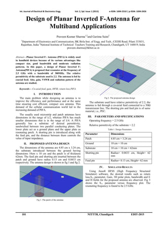
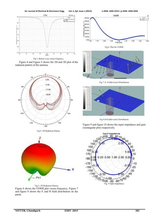
1) The document describes the design of a Planar Inverted F-Antenna (PIFA) that resonates at 2.5 GHz with a 300MHz bandwidth. 2) Key parameters of the proposed antenna design are described, including dimensions of the patch, ground, substrate, and position of the feeding and shorting pins. 3) Simulation results using HFSS are presented, including return loss, radiation patterns, voltage standing wave ratio (VSWR), and electric and magnetic field distributions. The antenna achieves the desired resonance frequency and has a maximum gain of 28.5362 dBi.