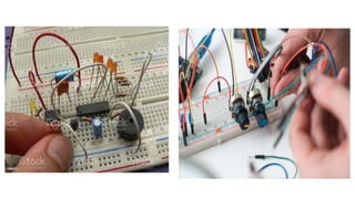
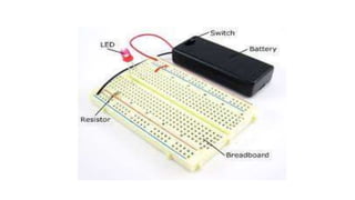
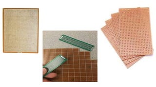
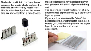
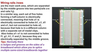
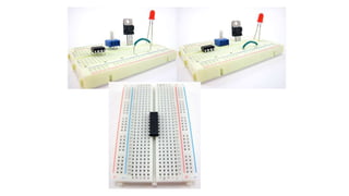
Breadboard
Priyanka jakhar
Physics (lecturer )
ATAL LAB Incharge
Breadboard
1. A breadboard is a circuit board that is used to make temporary circuits.
2. It is a device having electronics and test circuit designs.
3. The electronic elements inside the electronic circuits can be interchanged by
inserting the terminals and leads into holes and later connecting it with the
help of appropriate wires.
4. The device has stripes of metal below the board that connects the holes
placed on the top of the board.
5. The connections of the breadboard are mostly temporary and the elements
can further be reassembled and reused without any damage.
6. Breadboards are generally used in electrical engineering.
7. Engineers make use of breadboards in order to test different products made
by them.
8. Using breadboard is the most efficient way of testing and also they are cost
effective.
09. They can be reused again and again for the purpose of testing.
10. Breadboards earlier were made of copper wires or terminal strips.
11. These days it is made up of white plastic and is a breadboard that can be
plugged.
12. Breadboards are solderless and they are made of two kinds of strips i.e.
terminal and bus strips.
13. Terminal strips help in holding the electronic elements while the bus strip is
used to power electric power to all the electronic components.
14. The advantage of using a breadboard for testing is that connection can be
changed if they are wrong.
15. The parts of the circuit do not get damaged and can easily be reused.
16. A breadboard generally consists of lots of holes so that wires can easily be
pushed in.
17. Testing for almost every electronic projects starts from the breadboard.
18. On the whole, using a breadboard is very easy and as it gives immediate
results everyone prefers using it for testing different gadgets and electronic
products.
19. In the below diagram you can see alphabets are used in order to identify
vertical columns and numbers are used in order to identify vertical columns.
Breadboards come in two different versions;
solderless and solderable.
The solderless versions are the easiest to work with. Each row of
connected holes has a metal clip in the hole to capture the leads or
jumper wire connections that you will put into it.
A soldered breadboard, on the other hand, requires that each lead or
jumper wire be soldered into the hole. This makes the soldered
versions of more robust as the leads are permanently captured. Of
course, they are not as reusable as the solderless versions.
The term breadboard comes from the early days of electronics,
when people would literally drive nails or screws into wooden boards on which
they cut bread in order to connect their circuits.
Types of Breadboard
Breadboards are classified into two types like
a solderless breadboard a solder-able breadboard.
• This is the most commonly used breadboard for
prototyping as well as testing electronic circuits
without soldering the components.
• These are available in different shapes, sizes as well as
ratings.
• The circuits on these breadboards are not permanent
so we can check & test the functionality of a circuit
before confirming its design onto a PCB.
• These breadboards include rows & columns with holes
that allow the leads of components & wire gauges.
• If the terminal of the component does not place into the
hole of a breadboard, then a connecting wire can be
soldered to the lead of a component that will insert in
the breadboard hole.
• These types of breadboards offer a permanent setup for
your electronic circuits .
• This kind of breadboard gives a stronger setup. It
includes holes for electronic components including
copper tracing.
• These components can be soldered using soldering iron
for soldering the components to the breadboard so that
an electrical connection can be formed through the
copper tracing.
• For designing a circuit, jumper wires are needed for
soldering separately in between these components to
make a lane to permit the flow of current.
• These types of breadboards are available in different
sizes based on the requirement.
The leads can fit into the breadboard
because the inside of a breadboard is
made up of rows of tiny metal clips.
This is what the clips look like when
they are removed from a breadboard.
Most breadboards have a backing layer
that prevents the metal clips from falling
out.
The backing is typically a layer of sticky,
double-sided tape covered by a protective
layer of paper.
If you want to permanently "stick" the
breadboard to something (for example, a
robot), you just need to peel off the paper
layer to expose the sticky tape
underneath.
Row numbers and column letters help you identify
individual holes in the breadboard
columns
Buses----- The strips are marked by red and blue (or red
and black) lines, with plus (+) and minus (-) signs,
respectively. They are called the buses, also referred to
as rails.
power bus, positive bus, and voltage bus all refer to the
one next to the red line with the plus (+) sign.
negative bus and ground bus both refer to one next to
the blue (or black) line with the minus (-) sign.
Wiring rails /rows
are the main work area, which are separated
by the middle groove into two parts(rails a-e
and rails f-j).
In a similar way, each set of five holes
forming a half-column is electrically
connected, meaning that hole a1 is
electrically connected to holes b1, c1, d1
and e1, but not connected to hole a2,
because that hole is in a different column
with a separate set of medal clips.
Also holes a1- e1 is not connected to holes
f1, g1, h1, i1 and j1, because they are
electrically separated by the middle groove.
Tips: Normally there
is bulges and grooves on the sides of a
breadboard which allow you to splice
multiple same-sized breadboards together
Blue represents the ground bus and red is the high voltage bus. If you supply
power to any spot on the red side of the column, every hole in the column now has
voltage.
Similarly, if you do this with ground, the entire column will be what we call a “bus”
(i.e. all the holes in the column are ground).
The rows are linked together by little metal clips. These allow for jumper wires and
components (resistor, etc.) to be easily connected, but keeps them from easily
falling out.
Advantages
•It doesn’t require soldering to connect the
components on board.
•If the circuit is not working properly then, we can
easily check and rectify them by taken out the
components & replace them easily.
Disadvantages
•Components that are connected to the
breadboard can come loose once the breadboard
is pushed or moved.
•This kind of breadboard is available with high
parasitic capacitances because of the
capacitances among different components which
are being close to each other.
•These breadboards are restricted to below or 10
MHz frequencies.
Advantages
•These breadboards are robust and your circuit
will be very secured on this type of breadboard.
•This kind of breadboard gives your project a
more specialized look.
•Less cost and saves time while designing a
circuit.
Disadvantages
•If there is any error occurs in the circuit then de-
soldering may cause damage to components
•This board cannot be reused.
 It is used to make a temporary prototype for the electronics projects.
 This is reusable because it doesn’t need any soldering.
 These boards are less weight because the material used to make this board is a lightweight
plastic material.
 Testing can be done very easily.
 The arrangement of these components can be done very simply into the holes on the board to
make the design of a circuit.
 It is economical and simple to use.
 It does not use any difficult parts.
 Drilling is not necessary to connect the components because the holes on the board are
embedded already.
 Modifying can be done very quickly.
 We can add or remove the components on the breadboard.
 These boards are available in different sizes and shapes.
 These boards can be adjusted very easily.
Advantages of Breadboard
Disadvantages of Breadboard
 These boards are not used for high current applications.
 For low-frequency applications, low-frequency boards are not used.
 For making simple circuits, it needs more physical space.
 The number of connections on the breadboard can make the circuit messy because of several
wires.
 The connections on the board can be disturbed once the components are connected or removed.
 Reliable connections are less.
 Signaling is limited.
Breadboard Sizes
There are different sizes of breadboards are available in the market which is used based on the
application.
•Tiny Breadboard
•Little Breadboard Bits
•Half Size
•Large Breadboard
Mini
The internal structure of a mini sized breadboard
is almost the same as a half sized one.
Only it does not have the top and bottom 4 long
rows.
All it contains is the groups of terminals, which
are also less than those on a half sized one.
So naturally it is much smaller sized – so it is
called "mini"
Tiny
The internal structure of a tiny sized
breadboard is the same as a mini sized
one.
But tiny sized one is slightly longer; also
there are numbers and letters on it.
As mentioned before, the 5 terminals of
each group named from 1 to 20 are
connected vertically.
And horizontally, A to E and F to J
represents holes on
Half & Half+
The internal structure of a half sized
breadboard is the same as that of a half+
sized one.
The difference lies in their appearance:
there are two red and blue lines on a half+
sized breadboard, which a half sized one
dose note have
Little Breadboard Bits -----
These breadboards are available in different sizes like
4X4, 2X8, and 2X4. The 4×4 type includes hour strips
with four-pin terminal strips.
The 2×8 type includes 8 strips with two-pin terminal
strips.
The 2×4 boards include 4 strips with two-pin terminal
strips.
Full+
1) Holes in the top and bottom 4 rows
The breadboard has strips of metal which run
underneath the board and connect the holes on the
top of the board.
The metal strips are laid out .
Note that the top and bottom 4 rows of holes in total
are connected horizontally, marked with "+" and "-",
while the remaining holes are connected vertically.
Full
A full sized breadboard is a little bit different from a
full+ sized one. Plug a diode on the breadboard.
You can see the groups of terminals in the left half of
the long row are green; there is a division vertical line
in the middle, and groups on its right side are grey.
Therefore, each of the 4 long rows is segmented into
two.

Breadboard

  • 1.
  • 2.
    Breadboard 1. A breadboardis a circuit board that is used to make temporary circuits. 2. It is a device having electronics and test circuit designs. 3. The electronic elements inside the electronic circuits can be interchanged by inserting the terminals and leads into holes and later connecting it with the help of appropriate wires. 4. The device has stripes of metal below the board that connects the holes placed on the top of the board. 5. The connections of the breadboard are mostly temporary and the elements can further be reassembled and reused without any damage. 6. Breadboards are generally used in electrical engineering. 7. Engineers make use of breadboards in order to test different products made by them. 8. Using breadboard is the most efficient way of testing and also they are cost effective.
  • 3.
    09. They canbe reused again and again for the purpose of testing. 10. Breadboards earlier were made of copper wires or terminal strips. 11. These days it is made up of white plastic and is a breadboard that can be plugged. 12. Breadboards are solderless and they are made of two kinds of strips i.e. terminal and bus strips. 13. Terminal strips help in holding the electronic elements while the bus strip is used to power electric power to all the electronic components. 14. The advantage of using a breadboard for testing is that connection can be changed if they are wrong. 15. The parts of the circuit do not get damaged and can easily be reused. 16. A breadboard generally consists of lots of holes so that wires can easily be pushed in. 17. Testing for almost every electronic projects starts from the breadboard.
  • 4.
    18. On thewhole, using a breadboard is very easy and as it gives immediate results everyone prefers using it for testing different gadgets and electronic products. 19. In the below diagram you can see alphabets are used in order to identify vertical columns and numbers are used in order to identify vertical columns. Breadboards come in two different versions; solderless and solderable. The solderless versions are the easiest to work with. Each row of connected holes has a metal clip in the hole to capture the leads or jumper wire connections that you will put into it. A soldered breadboard, on the other hand, requires that each lead or jumper wire be soldered into the hole. This makes the soldered versions of more robust as the leads are permanently captured. Of course, they are not as reusable as the solderless versions.
  • 5.
    The term breadboardcomes from the early days of electronics, when people would literally drive nails or screws into wooden boards on which they cut bread in order to connect their circuits.
  • 8.
    Types of Breadboard Breadboardsare classified into two types like a solderless breadboard a solder-able breadboard. • This is the most commonly used breadboard for prototyping as well as testing electronic circuits without soldering the components. • These are available in different shapes, sizes as well as ratings. • The circuits on these breadboards are not permanent so we can check & test the functionality of a circuit before confirming its design onto a PCB. • These breadboards include rows & columns with holes that allow the leads of components & wire gauges. • If the terminal of the component does not place into the hole of a breadboard, then a connecting wire can be soldered to the lead of a component that will insert in the breadboard hole. • These types of breadboards offer a permanent setup for your electronic circuits . • This kind of breadboard gives a stronger setup. It includes holes for electronic components including copper tracing. • These components can be soldered using soldering iron for soldering the components to the breadboard so that an electrical connection can be formed through the copper tracing. • For designing a circuit, jumper wires are needed for soldering separately in between these components to make a lane to permit the flow of current. • These types of breadboards are available in different sizes based on the requirement.
  • 11.
    The leads canfit into the breadboard because the inside of a breadboard is made up of rows of tiny metal clips. This is what the clips look like when they are removed from a breadboard. Most breadboards have a backing layer that prevents the metal clips from falling out. The backing is typically a layer of sticky, double-sided tape covered by a protective layer of paper. If you want to permanently "stick" the breadboard to something (for example, a robot), you just need to peel off the paper layer to expose the sticky tape underneath.
  • 12.
    Row numbers andcolumn letters help you identify individual holes in the breadboard columns Buses----- The strips are marked by red and blue (or red and black) lines, with plus (+) and minus (-) signs, respectively. They are called the buses, also referred to as rails. power bus, positive bus, and voltage bus all refer to the one next to the red line with the plus (+) sign. negative bus and ground bus both refer to one next to the blue (or black) line with the minus (-) sign.
  • 13.
    Wiring rails /rows arethe main work area, which are separated by the middle groove into two parts(rails a-e and rails f-j). In a similar way, each set of five holes forming a half-column is electrically connected, meaning that hole a1 is electrically connected to holes b1, c1, d1 and e1, but not connected to hole a2, because that hole is in a different column with a separate set of medal clips. Also holes a1- e1 is not connected to holes f1, g1, h1, i1 and j1, because they are electrically separated by the middle groove. Tips: Normally there is bulges and grooves on the sides of a breadboard which allow you to splice multiple same-sized breadboards together
  • 14.
    Blue represents theground bus and red is the high voltage bus. If you supply power to any spot on the red side of the column, every hole in the column now has voltage. Similarly, if you do this with ground, the entire column will be what we call a “bus” (i.e. all the holes in the column are ground). The rows are linked together by little metal clips. These allow for jumper wires and components (resistor, etc.) to be easily connected, but keeps them from easily falling out.
  • 16.
    Advantages •It doesn’t requiresoldering to connect the components on board. •If the circuit is not working properly then, we can easily check and rectify them by taken out the components & replace them easily. Disadvantages •Components that are connected to the breadboard can come loose once the breadboard is pushed or moved. •This kind of breadboard is available with high parasitic capacitances because of the capacitances among different components which are being close to each other. •These breadboards are restricted to below or 10 MHz frequencies. Advantages •These breadboards are robust and your circuit will be very secured on this type of breadboard. •This kind of breadboard gives your project a more specialized look. •Less cost and saves time while designing a circuit. Disadvantages •If there is any error occurs in the circuit then de- soldering may cause damage to components •This board cannot be reused.
  • 17.
     It isused to make a temporary prototype for the electronics projects.  This is reusable because it doesn’t need any soldering.  These boards are less weight because the material used to make this board is a lightweight plastic material.  Testing can be done very easily.  The arrangement of these components can be done very simply into the holes on the board to make the design of a circuit.  It is economical and simple to use.  It does not use any difficult parts.  Drilling is not necessary to connect the components because the holes on the board are embedded already.  Modifying can be done very quickly.  We can add or remove the components on the breadboard.  These boards are available in different sizes and shapes.  These boards can be adjusted very easily. Advantages of Breadboard
  • 18.
    Disadvantages of Breadboard These boards are not used for high current applications.  For low-frequency applications, low-frequency boards are not used.  For making simple circuits, it needs more physical space.  The number of connections on the breadboard can make the circuit messy because of several wires.  The connections on the board can be disturbed once the components are connected or removed.  Reliable connections are less.  Signaling is limited.
  • 19.
    Breadboard Sizes There aredifferent sizes of breadboards are available in the market which is used based on the application. •Tiny Breadboard •Little Breadboard Bits •Half Size •Large Breadboard
  • 21.
    Mini The internal structureof a mini sized breadboard is almost the same as a half sized one. Only it does not have the top and bottom 4 long rows. All it contains is the groups of terminals, which are also less than those on a half sized one. So naturally it is much smaller sized – so it is called "mini"
  • 22.
    Tiny The internal structureof a tiny sized breadboard is the same as a mini sized one. But tiny sized one is slightly longer; also there are numbers and letters on it. As mentioned before, the 5 terminals of each group named from 1 to 20 are connected vertically. And horizontally, A to E and F to J represents holes on
  • 23.
    Half & Half+ Theinternal structure of a half sized breadboard is the same as that of a half+ sized one. The difference lies in their appearance: there are two red and blue lines on a half+ sized breadboard, which a half sized one dose note have
  • 24.
    Little Breadboard Bits----- These breadboards are available in different sizes like 4X4, 2X8, and 2X4. The 4×4 type includes hour strips with four-pin terminal strips. The 2×8 type includes 8 strips with two-pin terminal strips. The 2×4 boards include 4 strips with two-pin terminal strips.
  • 25.
    Full+ 1) Holes inthe top and bottom 4 rows The breadboard has strips of metal which run underneath the board and connect the holes on the top of the board. The metal strips are laid out . Note that the top and bottom 4 rows of holes in total are connected horizontally, marked with "+" and "-", while the remaining holes are connected vertically. Full A full sized breadboard is a little bit different from a full+ sized one. Plug a diode on the breadboard. You can see the groups of terminals in the left half of the long row are green; there is a division vertical line in the middle, and groups on its right side are grey. Therefore, each of the 4 long rows is segmented into two.