Download as PDF, PPTX

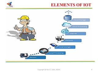
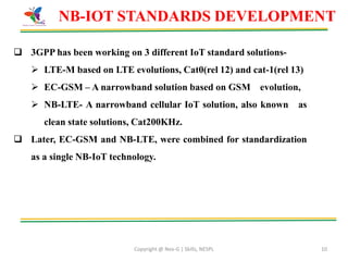
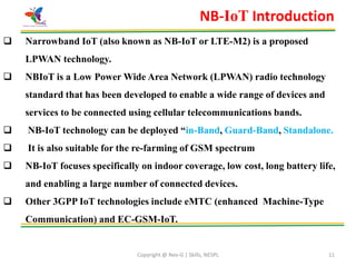
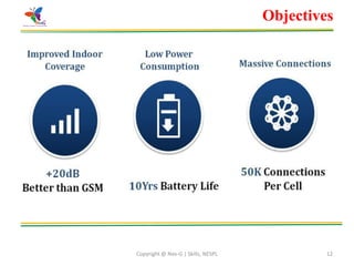
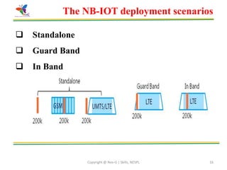
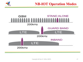
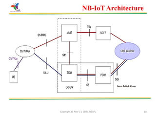
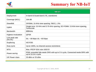
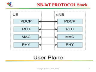
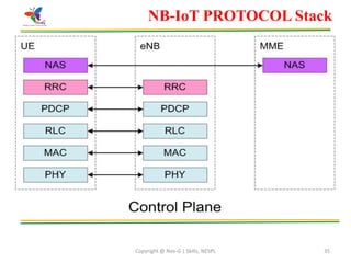
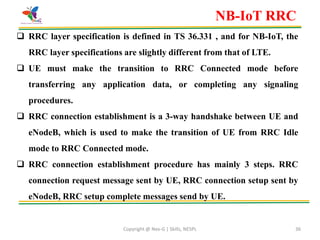
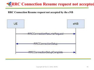
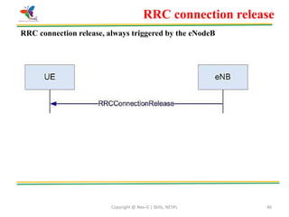
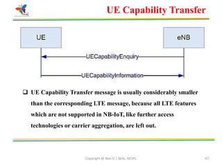
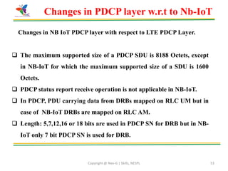
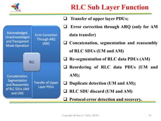
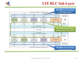


This document provides an overview of Narrow Band Internet of Things (NB IoT) technology. It begins with introductions to IoT and the key elements that make up IoT systems. It then describes NB IoT, including its objectives to enable low cost, long battery life connections for a large number of devices. The document outlines the NB IoT standards development and provides details on its deployment scenarios, operation modes, architecture and characteristics. It also summarizes the different layers of the NB IoT protocol stack, including the radio resource control layer.


![Lecture 5,6 [Autosavedaot IOT ]slides.pptx](https://cdn.slidesharecdn.com/ss_thumbnails/lecture56autosaved-250319212033-33ce99fb-thumbnail.jpg?width=640&height=640&fit=bounds)


