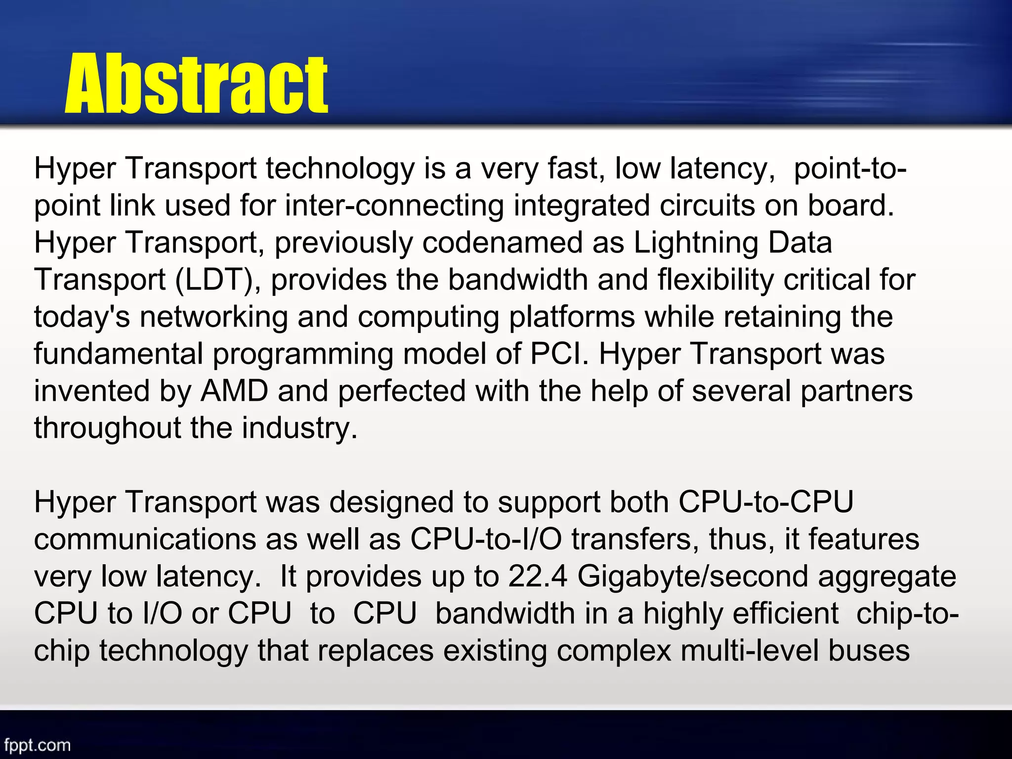
HyperTransport™
Technology
(A High-Bandwidth I/O Architecture )
SEMINAR ON
Group members are :- (T. Y. Btech.
Comp. Sci.)
1. Rohan R. Khude
2.Rina Kamble
3. Manjiri C. Patil
4. Ruksar Mulani
5.Akshata Doijad
Guidance by
Tirmare H. A.
Hyper Transport technology is a very fast, low latency, point-to-
point link used for inter-connecting integrated circuits on board.
Hyper Transport, previously codenamed as Lightning Data
Transport (LDT), provides the bandwidth and flexibility critical for
today's networking and computing platforms while retaining the
fundamental programming model of PCI. Hyper Transport was
invented by AMD and perfected with the help of several partners
throughout the industry.
Hyper Transport was designed to support both CPU-to-CPU
communications as well as CPU-to-I/O transfers, thus, it features
very low latency. It provides up to 22.4 Gigabyte/second aggregate
CPU to I/O or CPU to CPU bandwidth in a highly efficient chip-to-
chip technology that replaces existing complex multi-level buses
Abstract
Introduction
Old
Technology
problem
1.I/O Bandwidth Problem
2.Hyper Transport Solution
• While microprocessor performance continues to double every
eighteen months, the performance of the I/O bus architecture has lagged,
doubling in performance approximately every three years, as illustrated in
Figure 1.
• This I/O bottleneck constrains system performance, resulting in
diminished actual performance gains as the processor and memory
subsystems evolve. Over the past 20 years, a number of legacy buses, such
as ISA, VL-Bus, AGP, LPC, PCI-32/33, and PCI-X, have emerged that must
be bridged together to support a varying array of devices. Servers and
workstations require multiple high-speed buses, including PCI-64/66, AGP
Pro, and SNA buses like InfiniBand. The hodge-podge of buses increases
system complexity, adds many transistors devoted to bus arbitration and
bridge logic, while delivering less than optimal performance.
1.I/O Bandwidth Problem
2.Hyper Transport Solution
Original Design
Goals
Improve system performance
Simplify system design
Increase I/O flexibility
Maintain compatibility with legacy system
Ensure extensibility to new system network architecture
Provide highly scalable multiprocessing system
Conceptually, the architecture of the
HyperTransport I/O link can be mapped into five different
layers, which structure is similar to the Open System
Interconnection (OSI) reference model.
In HyperTransport technology:
 Physical layer
 Datalink layer
 Protocol layer
 Transaction layer
 Session layer
Flexible I/O Architecture
 Minimize Latency when transferring from HyperTransport™ to
Hyper Transport
 Maximize Bandwidth when transferring to and from PCI-X
 Provide 80% or more utilizable PCI-X bandwidth
 Hot-Plug Support
 Utilize ASIC flow for development and implementation
Architectural Goals
 Do not make acceptance of a posted request dependent upon the ability to
issue another request.
 Do not make acceptance of a nonposted request dependent upon the ability
to issue another nonposted request.
 Do not make acceptance of a request dependent upon receipt of a response.
 Do not make issuance of a response dependent upon the ability to issue a
nonposted request.
 Do not make issuance of a response dependent upon receipt of a response.
Ordering Rules (Row Pass Column?)
Posted Non-Posted Response
Posted | No | Yes | Yes
Non-Posted | No | Yes/No | Yes/No
Response | No | Yes | Yes/No
Deadlock avoidance strategy
HyperTransport™ Technology
Pins
Device
Configurations
• Cave
• Tunnel
• Bridge
Device Configurations
Working of I/O
Architechture
1.Physical Layer
2. Data Link Layer
3. Protocol Layer
4. Transaction Layer
5. Session Layer
Physical Layer
Electrical Configuration
• The signaling technology used in HyperTransport technology is a
type of low voltage differential signaling (LVDS ).
• HyperTransport links implement double data rate (DDR)
transfer, where transfers take place on both the rising
and falling edges of the clock signal.
• An implementation of HyperTransport links with 16 CAD
bits in each direction with a 1.6-GHz data rate provides
bandwidth of 3.2 Gigabytes per second in each direction,
for an aggregate peak bandwidth of 6.4 Gbytes/s, or 48
times the peak bandwidth of a 33-MHz PCI bus.
Maximum Bandwidth
Minimal Pin Count
• The data link layer includes the
initialization and configuration sequence,
periodic cyclic redundancy check (CRC),
disconnect/reconnect sequence,
information packets for flow control and
error management, and doubleword
framing for other packets.
Data Link Layer
• The protocol layer includes the
commands, the virtual channels in which
they run, and the ordering rules that
govern their flow.
• The transaction layer uses the elements
provided by the protocol layer to perform
actions, such as read request and
responses.
Protocol and Transaction
Layers
• The session layer includes link width
optimization and link frequency
optimization along with interrupt and
power state capabilities.
Session Layer
Hyper Transport
Environments
Overall
Features &
Function
Hardware
Software
Hardware Feature
Software Feature
• Supports Windows Server® 2003, Windows Server® 2008,
Red Hat Enterprise Linux, SUSE Linux, and Solaris.
• Supports corporate manageability requirements
• ACPI support.
• OS and API support
.
• Power Management support
Hyper Transport
Packet Based
Protocol
1. Packet Based
2. Low packet Overhead
Packet based
Low packet overhead
HT-Link
Diagram: HT-Link
•
control pair
• Clock Clock Pair
• 2,4,8,16,32 Data Pairs
clock pair
control pair
2,4,8,16,32 Data Pairs
RESET_L
PWORK
VHT
GND
HyperTransport
Device A
HyperTransport
Device B
HT Devices
• Host Bridge : HT interface that provide
connectivity between system’s host processor.
• End-Chain Link :The Altera
HyperTransport MegaCore function
implements an end-chain link.
• Tunnel :A tunnel is a dual-link device that
is not a HyperTransport-to-HyperTransport
bridge.
• HyperTransport-to-HyperTransport
Bridge : This bridge has one or more HT
links and is more complex than a tunnel
because
How will HTT
change the
Motherboard
AMD HTT device in Main Motherboard
HTX Expansion Slot
Implementation
Examples
1. Daisy Chain Topology
2. Switch Topology
3. Star Topology
4. Multiprocessor implementation
1. Daisy Chain Topology
2. Switch topology
3. Star topology
4. Multiprocessor implementation
General Examples
of HTT
-- Graphics & 3D rendering
-- Security processing
-- Real Time data/packet analysis
-- Media processing
-- Co-processing
Example Co-processing
Case Study
Advantages
System faster
High speed
Low power consumption
Minimal pin count
Low cost
Low latency
Narrow buses
Maximum bandwidth
Point-to-point connection
Disadvantages
Cross talk
 The spectrum of IO technology
 Traditional inside the box verses outside the box
 Point to point inside the box verses outside the box
 Traditional shared buses verses point to point
interconnection
 Serial links verses parallel point to point link
Comparisons with other technologies
Shared buses
Point to point parallel buses
Application
Front-side bus replacement
Multiprocessor Interconnect
Router or switch bus replacement
Coprocessor interconnect
Add on card connector
Conclusion
THANK YOU
Any

Hyper Transport Technology

  • 1.
  • 2.
    Group members are:- (T. Y. Btech. Comp. Sci.) 1. Rohan R. Khude 2.Rina Kamble 3. Manjiri C. Patil 4. Ruksar Mulani 5.Akshata Doijad Guidance by Tirmare H. A.
  • 3.
    Hyper Transport technologyis a very fast, low latency, point-to- point link used for inter-connecting integrated circuits on board. Hyper Transport, previously codenamed as Lightning Data Transport (LDT), provides the bandwidth and flexibility critical for today's networking and computing platforms while retaining the fundamental programming model of PCI. Hyper Transport was invented by AMD and perfected with the help of several partners throughout the industry. Hyper Transport was designed to support both CPU-to-CPU communications as well as CPU-to-I/O transfers, thus, it features very low latency. It provides up to 22.4 Gigabyte/second aggregate CPU to I/O or CPU to CPU bandwidth in a highly efficient chip-to- chip technology that replaces existing complex multi-level buses Abstract
  • 4.
  • 5.
  • 6.
    • While microprocessorperformance continues to double every eighteen months, the performance of the I/O bus architecture has lagged, doubling in performance approximately every three years, as illustrated in Figure 1. • This I/O bottleneck constrains system performance, resulting in diminished actual performance gains as the processor and memory subsystems evolve. Over the past 20 years, a number of legacy buses, such as ISA, VL-Bus, AGP, LPC, PCI-32/33, and PCI-X, have emerged that must be bridged together to support a varying array of devices. Servers and workstations require multiple high-speed buses, including PCI-64/66, AGP Pro, and SNA buses like InfiniBand. The hodge-podge of buses increases system complexity, adds many transistors devoted to bus arbitration and bridge logic, while delivering less than optimal performance. 1.I/O Bandwidth Problem
  • 8.
  • 9.
    Original Design Goals Improve systemperformance Simplify system design Increase I/O flexibility Maintain compatibility with legacy system Ensure extensibility to new system network architecture Provide highly scalable multiprocessing system
  • 10.
    Conceptually, the architectureof the HyperTransport I/O link can be mapped into five different layers, which structure is similar to the Open System Interconnection (OSI) reference model. In HyperTransport technology:  Physical layer  Datalink layer  Protocol layer  Transaction layer  Session layer Flexible I/O Architecture
  • 11.
     Minimize Latencywhen transferring from HyperTransport™ to Hyper Transport  Maximize Bandwidth when transferring to and from PCI-X  Provide 80% or more utilizable PCI-X bandwidth  Hot-Plug Support  Utilize ASIC flow for development and implementation Architectural Goals
  • 12.
     Do notmake acceptance of a posted request dependent upon the ability to issue another request.  Do not make acceptance of a nonposted request dependent upon the ability to issue another nonposted request.  Do not make acceptance of a request dependent upon receipt of a response.  Do not make issuance of a response dependent upon the ability to issue a nonposted request.  Do not make issuance of a response dependent upon receipt of a response. Ordering Rules (Row Pass Column?) Posted Non-Posted Response Posted | No | Yes | Yes Non-Posted | No | Yes/No | Yes/No Response | No | Yes | Yes/No Deadlock avoidance strategy
  • 15.
  • 16.
  • 17.
  • 18.
    Working of I/O Architechture 1.PhysicalLayer 2. Data Link Layer 3. Protocol Layer 4. Transaction Layer 5. Session Layer
  • 19.
  • 21.
    Electrical Configuration • Thesignaling technology used in HyperTransport technology is a type of low voltage differential signaling (LVDS ).
  • 22.
    • HyperTransport linksimplement double data rate (DDR) transfer, where transfers take place on both the rising and falling edges of the clock signal. • An implementation of HyperTransport links with 16 CAD bits in each direction with a 1.6-GHz data rate provides bandwidth of 3.2 Gigabytes per second in each direction, for an aggregate peak bandwidth of 6.4 Gbytes/s, or 48 times the peak bandwidth of a 33-MHz PCI bus. Maximum Bandwidth
  • 23.
  • 24.
    • The datalink layer includes the initialization and configuration sequence, periodic cyclic redundancy check (CRC), disconnect/reconnect sequence, information packets for flow control and error management, and doubleword framing for other packets. Data Link Layer
  • 25.
    • The protocollayer includes the commands, the virtual channels in which they run, and the ordering rules that govern their flow. • The transaction layer uses the elements provided by the protocol layer to perform actions, such as read request and responses. Protocol and Transaction Layers
  • 27.
    • The sessionlayer includes link width optimization and link frequency optimization along with interrupt and power state capabilities. Session Layer
  • 28.
  • 29.
  • 30.
  • 31.
    Software Feature • SupportsWindows Server® 2003, Windows Server® 2008, Red Hat Enterprise Linux, SUSE Linux, and Solaris. • Supports corporate manageability requirements • ACPI support. • OS and API support . • Power Management support
  • 32.
    Hyper Transport Packet Based Protocol 1.Packet Based 2. Low packet Overhead
  • 33.
  • 34.
  • 36.
  • 37.
    Diagram: HT-Link • control pair •Clock Clock Pair • 2,4,8,16,32 Data Pairs clock pair control pair 2,4,8,16,32 Data Pairs RESET_L PWORK VHT GND HyperTransport Device A HyperTransport Device B
  • 38.
    HT Devices • HostBridge : HT interface that provide connectivity between system’s host processor. • End-Chain Link :The Altera HyperTransport MegaCore function implements an end-chain link. • Tunnel :A tunnel is a dual-link device that is not a HyperTransport-to-HyperTransport bridge.
  • 39.
    • HyperTransport-to-HyperTransport Bridge :This bridge has one or more HT links and is more complex than a tunnel because
  • 40.
    How will HTT changethe Motherboard
  • 41.
    AMD HTT devicein Main Motherboard
  • 42.
  • 43.
    Implementation Examples 1. Daisy ChainTopology 2. Switch Topology 3. Star Topology 4. Multiprocessor implementation
  • 44.
  • 45.
  • 46.
  • 47.
  • 48.
    General Examples of HTT --Graphics & 3D rendering -- Security processing -- Real Time data/packet analysis -- Media processing -- Co-processing
  • 49.
  • 50.
  • 51.
    Advantages System faster High speed Lowpower consumption Minimal pin count Low cost Low latency Narrow buses Maximum bandwidth Point-to-point connection
  • 52.
  • 53.
     The spectrumof IO technology  Traditional inside the box verses outside the box  Point to point inside the box verses outside the box  Traditional shared buses verses point to point interconnection  Serial links verses parallel point to point link Comparisons with other technologies
  • 54.
  • 55.
    Point to pointparallel buses
  • 56.
    Application Front-side bus replacement MultiprocessorInterconnect Router or switch bus replacement Coprocessor interconnect Add on card connector
  • 59.
  • 60.
  • 61.