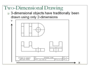
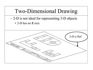
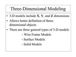
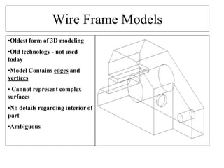
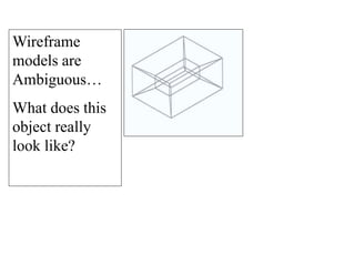
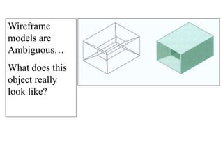
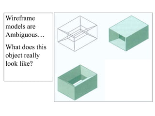
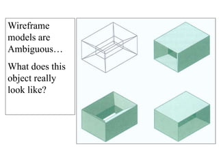
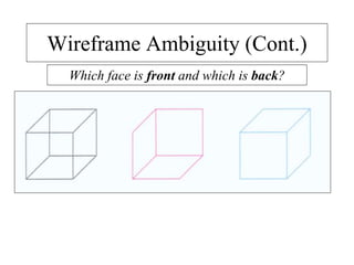
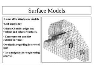
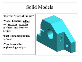
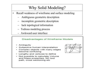
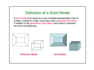
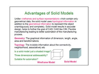
UNIT - 4
SOLID MODELING
(PART -1)
Two-Dimensional Drawing
– 2-D is not ideal for representing 3-D objects
• 2-D has no Z axis
2-D is flat!
Three-Dimensional Modeling
• 3-D models include X, Y, and Z dimensions
• Allows better definition of three-
dimensional objects
• There are three general types of 3-D models
- Wire Frame Models
- Surface Models
- Solid Models
Wire Frame Models
•Oldest form of 3D modeling
•Old technology - not used
today
•Model Contains edges and
vertices
• Cannot represent complex
surfaces
•No details regarding interior of
part
•Ambiguous
Wireframe
models are
Ambiguous…
What does this
object really
look like?
Wireframe
models are
Ambiguous…
What does this
object really
look like?
Wireframe
models are
Ambiguous…
What does this
object really
look like?
Wireframe
models are
Ambiguous…
What does this
object really
look like?
Wireframe
models are
Ambiguous…
What does this
object really
look like?
Wireframe Ambiguity (Cont.)
Which face is front and which is back?
Wireframe Ambiguity (Cont.)
Which face is front and which is back?
Wireframe Ambiguity (Cont.)
Which face is front and which is back?
Surface Models
•Came after Wireframe models
•Still used today
•Model Contains edges and
vertices and exterior surfaces
• Can represent complex
exterior surfaces
•No details regarding interior of
part
•Too ambiguous for engineering
analysis
Solid Models
•Current “state of the art”
•Model Contains edges
and vertices , exterior
surfaces, and interior
details
•Part is unambiguously
defined
•May be used for
engineering analysis
Why Solid Modeling?
• Recall weakness of wireframe and surface modeling
– Ambiguous geometric description
– incomplete geometric description
– lack topological information
– Tedious modeling process
– Awkward user interface
Solid model
• Solid modeling is based on complete, valid and unambiguous
geometric representation of physical object.
– Complete  points in space can be classified.(inside/
outside)
– Valid vertices, edges, faces are connected properly.
– Unambiguous  there can only be one interpretation of
object
• Analysis automation and integration is possible only with solid
models has properties such as weight, moment of inertia,
mass.
• Solid model consist of geometric and topological data
– Geometry  shape, size, location of geometric elements
– Topology connectivity and associatively of geometric
elements non graphical, relational information
Solid model representation schemes
1. Primitive instancing
2. Regularized Boolean set operations
3. Sweep representations.
4. Boundary representations (B-reps)
5. Constructive solid geometry (CSG)
6. Spatial-partitioning representations
- Octree representation
Primitives
Primitives in-use
Boundary representation (B-Rep)
• Solid model is defined by their enclosing surfaces or boundaries. This
technique consists of the geometric information about the faces, edges and
vertices of an object with the topological data on how these are connected.
• Why B-Rep includes such topological information?
- A solid is represented as a closed space in 3D space (surface connect
without gaps)
- The boundary of a solid separates points inside from points outside solid.
• Surface model
– A collection of surface entities which simply enclose a volume lacks the
connective data to define a solid (i.e topology).
• B- Rep model
– Technique guarantees that surfaces definitively divide model space into
solid and void, even after model modification commands.
– B-Rep graph store face, edge and vertices as nodes, with pointers, or
branches between the nodes to indicate connectivity.
Boundary representation- validity
• System must validate topology of created solid.
• B-Rep has to fulfill certain conditions to disallow self-
intersecting and open objects
• This condition include
– Each edge should adjoin exactly two faces and have a vertex
at each end.
– Vertices are geometrically described by point coordinates
– At least three edges must meet at each vertex.
– Faces are described by surface equations
– The set of faces forms a complete skin of the solid with no
missing parts.
– Each face is bordered by an ordered set of edges forming a
closed loop.
– Faces must only intersect at common edges or vertices.
– The boundaries of faces do not intersect themselves
B-Rep data structure
solid
face1 face2 face3 face4 face5
edge1 edge2 edge3 edge4 edge5 edge6 edge7 edge8
vertex1 vertex2 vertex3 vertex4 vertex5
f1
f2f3
f4 f5
E1
E2
E3
E4
E5
E6
E7
E8
v1 v2
v3v4
v5
(x, y, z)
Combinatorial
structure /
topology
Metric information/
geometry
• Valid B-Reps are unambiguous
• Not fully unique, but much more so than CSG
• Potential difference exists in division of
– Surfaces into faces.
– Curves into edges
• Capability to construct unusual shapes that would not be possible with
the available CSG aircraft fuselages, swing shapes
• Less computational time to reconstruct the image
• Requires more storage
• More prone to validity failure than CSG
• Model display limited to planar faces and linear edges
– complex curve and surfaces only approximated
Boundary representation-
ambiguity and uniqueness
Constructive Solid Geometry
Constructive solid geometry (CSG)
• Objects are represented as a combination of simpler solid objects
(primitives).
• The primitives are such as cube, cylinder, cone, torus, sphere etc.
• Copies or “instances” of these primitive shapes are created and
positioned.
• A complete solid model is constructed by combining these “instances”
using set specific, logic operations (Boolean)
• Boolean operation
– each primitive solid is assumed to be a set of points, a boolean
operation is performed on point sets and the result is a solid model.
– Boolean operation  union, intersection and difference
– The relative location and orientation of the two primitives have to
be defined before the boolean operation can be performed.
– Boolean operation can be applied to two solids other than the
primitives.
Constructive Solid Geometry Methods
• Constructive Solid Geometry (CSG)
performs solid modelling by generating a
new object from two 3-dimensional objects
using a set operation
• Valid set operations include
– Union
– Intersection
– Difference
CSG Operations
• Primitives:
• Union:
• Intersection:
• Difference:
Constructive Solid Geometry Methods
(cont…)
Constructive Solid Geometry Methods
(cont…)
• CSG usually starts with a small set of
primitives such as blocks, pyramids, spheres
and cones
• Two objects re initially created and combined
using some set operation to create a new object
• This object can then be combined with another
primitive to make another new object
• This process continues until modelling
complete
Constructive Solid Geometry Methods
(cont…)
CSG
Object
oper
1
obj1 obj2
oper
3
obj4
oper
2
obj2 obj3
• CSG models are
usually represented
as CSG trees
Constructive solid geometry
(CSG)- CSG tree
+
-
Ray-Casting
• Ray-casting is typically used to implement
CSG operators when objects are described with
boundary representations
• Ray casting is applied by determining the
objects that are intersected by a set of parallel
lines emanating from the xy plane along the z
axis
• The xy plane is referred to as the firing plane
Ray-Casting (cont…)
ImagestakenfromHearn&Baker,“ComputerGraphicswithOpenGL”(2004)
Ray-Casting (cont…)
• Surface intersections along each ray are
calculated and these are sorted according to
distance from the firing plane
• The surface limits for the composite object
are then determined by the specified set
operation
Ray Casting Example
ImagestakenfromHearn&Baker,“ComputerGraphicswithOpenGL”(2004)
CSG Data Structure
• typedef struct _csgtree
– Operator op;
– Quadric primitive;
– struct _csgtree *right;
– struct _csgtree *left;
• } CSGTreePtr;
• Each leaf node represents a primitive (usually a
quadric primitive).
• ‘op’ can also be ‘leaf’ rather than a combination
operator.
Intersecting a Ray
• Pseudo code for ray-tree intersection
Intersecting a Ray
• The result will be a sequence of intersection
points along a ray, represented by the
parametric values
– t0, t1, t2, …,tn
– where there are n intersections
• Each individual intersection with a solid
will result (typically) in two values.
• When using Boolean operation, be careful
to avoid situation that do not result in a
invalid solid
Constructive solid geometry (CSG)-
Boolean operation
A  B
A B
• Boolean operation
– Are intuitive to user
– Are easy to use and understand
– Provide for the rapid manipulation of large amounts of data.
• Because of this, many non-CSG systems also use Boolean operations
• Data structure does not define model shape explicitly but rather implies the
geometric shape through a procedural description
– E.g: object is not defined as a set of edges & faces but by the instruction :
union primitive1 with primitive 2
• This procedural data is stored in a data structure referred to as a CSG tree
• The data structure is simple and stores compact data  easy to manage
• CSG tree  stores the history of applying boolean operations on the
primitives.
– Stores in a binary tree format
– The outer leaf nodes of tree represent the primitives
– The interior nodes represent the boolean operations performed.
Constructive Solid Geometry (CSG)- Boolean operation
Advantage
• CSG is powerful with high level command.
• Easy to construct a solid model – minimum step.
• CSG modeling techniques lead to a concise database less storage.
– Complete history of model is retained and can be altered at any
point.
• Can be converted to the corresponding boundary representation.
Disadvantage
• Only boolean operations are allowed in the modeling process  with
boolean operation alone, the range of shapes to be modeled is severely
restricted  not possible to construct unusual shape.
• Requires a great deal of computation to derive the information on the
boundary, faces and edges which is important for the interactive
display/ manipulation of solid.
Constructive Solid Geometry (CSG) –
Advantage and Disadvantage
Examples
www-2.cs.cmu.edu/afs/cs/misc/rayshade/
all_mach/omega/doc/Examples/jpg/csg.jpg
ccvweb.csres.utexas.edu/ccv/projects/VisualEyes/
visualization/domainpara/algebraic2/parameterization/
gallery/Reconstruction/Csg/
Octrees
• Hierarchical tree structures, called
Octrees, are used to represent solid
objects in some graphics systems.
• The fundamental idea behind both
the quadtree and octrees is the
divide and conquer power of
binary
sub division.
• For a heterogeneous region of
space, the successive sub-division
into quadrants continues until all
quadrants are homogenous color.
• It also provides a convenient
representation for storing
information about object interiors.
• Quadtree is used to speed up 3-D
picking in graphics package.
Octrees Advantages and applications
• Medical Imaging and other applications that require displays of
object cross sections commonly use octrees representation
• This representation for solids takes advantage of spatial
coherence to reduce storage requirements for solids 3-D
Objects.
• 3-D octrees rotations are accomplished by applying the
transformations to the occupied octants.
• Visible Surface Detection (or) Hidden Surface elimination is
accomplished by projecting octrees nodes on to the viewing
surface in a front to back order.
• Individual elements of a 3-D space are called volume elements
(or) voxels.
2D-Quadtree
• A node either has 4 children or none
• Construct a quadtree with rule as no more than 3 dots
can exist in a square.
2D-Quadtree
• A node either has 4 children or none
• The below quadtree has a rule that no more than 3
dots can exist in a square.
Parameter Sweeps B-reps CSG Octree
Accuracy High
Sometimes
Requires
approx.
High High
Domain Limited
Can Represent
wide class of
objects
Limited to
some extend
Limited
Uniqueness Unique Unique Not Unique Unique
Validity
Easy to
Validate
Most difficult
to validate
Easy to
Validate
Easy to
Validate
Closure
Not closed
under
Boolean
operations
May suffer
from closure
problems
under Boolean
operations
Closed Closed
Compactness
More
Compact and
efficient
Compact and
evaluation is
not necessary
More Compact
needs
evaluation of
Boolean
operations and
transformation
Compact

Solid modelling cg

  • 1.
    UNIT - 4 SOLIDMODELING (PART -1)
  • 3.
    Two-Dimensional Drawing – 2-Dis not ideal for representing 3-D objects • 2-D has no Z axis 2-D is flat!
  • 4.
    Three-Dimensional Modeling • 3-Dmodels include X, Y, and Z dimensions • Allows better definition of three- dimensional objects • There are three general types of 3-D models - Wire Frame Models - Surface Models - Solid Models
  • 5.
    Wire Frame Models •Oldestform of 3D modeling •Old technology - not used today •Model Contains edges and vertices • Cannot represent complex surfaces •No details regarding interior of part •Ambiguous
  • 6.
    Wireframe models are Ambiguous… What doesthis object really look like?
  • 7.
    Wireframe models are Ambiguous… What doesthis object really look like?
  • 8.
    Wireframe models are Ambiguous… What doesthis object really look like?
  • 9.
    Wireframe models are Ambiguous… What doesthis object really look like?
  • 10.
    Wireframe models are Ambiguous… What doesthis object really look like?
  • 11.
    Wireframe Ambiguity (Cont.) Whichface is front and which is back?
  • 12.
    Wireframe Ambiguity (Cont.) Whichface is front and which is back?
  • 13.
    Wireframe Ambiguity (Cont.) Whichface is front and which is back?
  • 14.
    Surface Models •Came afterWireframe models •Still used today •Model Contains edges and vertices and exterior surfaces • Can represent complex exterior surfaces •No details regarding interior of part •Too ambiguous for engineering analysis
  • 15.
    Solid Models •Current “stateof the art” •Model Contains edges and vertices , exterior surfaces, and interior details •Part is unambiguously defined •May be used for engineering analysis
  • 17.
    Why Solid Modeling? •Recall weakness of wireframe and surface modeling – Ambiguous geometric description – incomplete geometric description – lack topological information – Tedious modeling process – Awkward user interface
  • 20.
    Solid model • Solidmodeling is based on complete, valid and unambiguous geometric representation of physical object. – Complete  points in space can be classified.(inside/ outside) – Valid vertices, edges, faces are connected properly. – Unambiguous  there can only be one interpretation of object • Analysis automation and integration is possible only with solid models has properties such as weight, moment of inertia, mass. • Solid model consist of geometric and topological data – Geometry  shape, size, location of geometric elements – Topology connectivity and associatively of geometric elements non graphical, relational information
  • 28.
    Solid model representationschemes 1. Primitive instancing 2. Regularized Boolean set operations 3. Sweep representations. 4. Boundary representations (B-reps) 5. Constructive solid geometry (CSG) 6. Spatial-partitioning representations - Octree representation
  • 29.
  • 30.
  • 45.
    Boundary representation (B-Rep) •Solid model is defined by their enclosing surfaces or boundaries. This technique consists of the geometric information about the faces, edges and vertices of an object with the topological data on how these are connected. • Why B-Rep includes such topological information? - A solid is represented as a closed space in 3D space (surface connect without gaps) - The boundary of a solid separates points inside from points outside solid. • Surface model – A collection of surface entities which simply enclose a volume lacks the connective data to define a solid (i.e topology). • B- Rep model – Technique guarantees that surfaces definitively divide model space into solid and void, even after model modification commands. – B-Rep graph store face, edge and vertices as nodes, with pointers, or branches between the nodes to indicate connectivity.
  • 46.
    Boundary representation- validity •System must validate topology of created solid. • B-Rep has to fulfill certain conditions to disallow self- intersecting and open objects • This condition include – Each edge should adjoin exactly two faces and have a vertex at each end. – Vertices are geometrically described by point coordinates – At least three edges must meet at each vertex. – Faces are described by surface equations – The set of faces forms a complete skin of the solid with no missing parts. – Each face is bordered by an ordered set of edges forming a closed loop. – Faces must only intersect at common edges or vertices. – The boundaries of faces do not intersect themselves
  • 53.
    B-Rep data structure solid face1face2 face3 face4 face5 edge1 edge2 edge3 edge4 edge5 edge6 edge7 edge8 vertex1 vertex2 vertex3 vertex4 vertex5 f1 f2f3 f4 f5 E1 E2 E3 E4 E5 E6 E7 E8 v1 v2 v3v4 v5 (x, y, z) Combinatorial structure / topology Metric information/ geometry
  • 54.
    • Valid B-Repsare unambiguous • Not fully unique, but much more so than CSG • Potential difference exists in division of – Surfaces into faces. – Curves into edges • Capability to construct unusual shapes that would not be possible with the available CSG aircraft fuselages, swing shapes • Less computational time to reconstruct the image • Requires more storage • More prone to validity failure than CSG • Model display limited to planar faces and linear edges – complex curve and surfaces only approximated Boundary representation- ambiguity and uniqueness
  • 55.
  • 56.
    Constructive solid geometry(CSG) • Objects are represented as a combination of simpler solid objects (primitives). • The primitives are such as cube, cylinder, cone, torus, sphere etc. • Copies or “instances” of these primitive shapes are created and positioned. • A complete solid model is constructed by combining these “instances” using set specific, logic operations (Boolean) • Boolean operation – each primitive solid is assumed to be a set of points, a boolean operation is performed on point sets and the result is a solid model. – Boolean operation  union, intersection and difference – The relative location and orientation of the two primitives have to be defined before the boolean operation can be performed. – Boolean operation can be applied to two solids other than the primitives.
  • 57.
    Constructive Solid GeometryMethods • Constructive Solid Geometry (CSG) performs solid modelling by generating a new object from two 3-dimensional objects using a set operation • Valid set operations include – Union – Intersection – Difference
  • 58.
    CSG Operations • Primitives: •Union: • Intersection: • Difference:
  • 59.
    Constructive Solid GeometryMethods (cont…)
  • 60.
    Constructive Solid GeometryMethods (cont…) • CSG usually starts with a small set of primitives such as blocks, pyramids, spheres and cones • Two objects re initially created and combined using some set operation to create a new object • This object can then be combined with another primitive to make another new object • This process continues until modelling complete
  • 61.
    Constructive Solid GeometryMethods (cont…) CSG Object oper 1 obj1 obj2 oper 3 obj4 oper 2 obj2 obj3 • CSG models are usually represented as CSG trees
  • 63.
  • 64.
    Ray-Casting • Ray-casting istypically used to implement CSG operators when objects are described with boundary representations • Ray casting is applied by determining the objects that are intersected by a set of parallel lines emanating from the xy plane along the z axis • The xy plane is referred to as the firing plane
  • 65.
  • 66.
    Ray-Casting (cont…) • Surfaceintersections along each ray are calculated and these are sorted according to distance from the firing plane • The surface limits for the composite object are then determined by the specified set operation
  • 67.
  • 68.
    CSG Data Structure •typedef struct _csgtree – Operator op; – Quadric primitive; – struct _csgtree *right; – struct _csgtree *left; • } CSGTreePtr; • Each leaf node represents a primitive (usually a quadric primitive). • ‘op’ can also be ‘leaf’ rather than a combination operator.
  • 69.
    Intersecting a Ray •Pseudo code for ray-tree intersection
  • 70.
    Intersecting a Ray •The result will be a sequence of intersection points along a ray, represented by the parametric values – t0, t1, t2, …,tn – where there are n intersections • Each individual intersection with a solid will result (typically) in two values.
  • 71.
    • When usingBoolean operation, be careful to avoid situation that do not result in a invalid solid Constructive solid geometry (CSG)- Boolean operation A  B A B
  • 72.
    • Boolean operation –Are intuitive to user – Are easy to use and understand – Provide for the rapid manipulation of large amounts of data. • Because of this, many non-CSG systems also use Boolean operations • Data structure does not define model shape explicitly but rather implies the geometric shape through a procedural description – E.g: object is not defined as a set of edges & faces but by the instruction : union primitive1 with primitive 2 • This procedural data is stored in a data structure referred to as a CSG tree • The data structure is simple and stores compact data  easy to manage • CSG tree  stores the history of applying boolean operations on the primitives. – Stores in a binary tree format – The outer leaf nodes of tree represent the primitives – The interior nodes represent the boolean operations performed. Constructive Solid Geometry (CSG)- Boolean operation
  • 73.
    Advantage • CSG ispowerful with high level command. • Easy to construct a solid model – minimum step. • CSG modeling techniques lead to a concise database less storage. – Complete history of model is retained and can be altered at any point. • Can be converted to the corresponding boundary representation. Disadvantage • Only boolean operations are allowed in the modeling process  with boolean operation alone, the range of shapes to be modeled is severely restricted  not possible to construct unusual shape. • Requires a great deal of computation to derive the information on the boundary, faces and edges which is important for the interactive display/ manipulation of solid. Constructive Solid Geometry (CSG) – Advantage and Disadvantage
  • 74.
  • 75.
    Octrees • Hierarchical treestructures, called Octrees, are used to represent solid objects in some graphics systems. • The fundamental idea behind both the quadtree and octrees is the divide and conquer power of binary sub division. • For a heterogeneous region of space, the successive sub-division into quadrants continues until all quadrants are homogenous color. • It also provides a convenient representation for storing information about object interiors. • Quadtree is used to speed up 3-D picking in graphics package.
  • 76.
    Octrees Advantages andapplications • Medical Imaging and other applications that require displays of object cross sections commonly use octrees representation • This representation for solids takes advantage of spatial coherence to reduce storage requirements for solids 3-D Objects. • 3-D octrees rotations are accomplished by applying the transformations to the occupied octants. • Visible Surface Detection (or) Hidden Surface elimination is accomplished by projecting octrees nodes on to the viewing surface in a front to back order. • Individual elements of a 3-D space are called volume elements (or) voxels.
  • 78.
    2D-Quadtree • A nodeeither has 4 children or none • Construct a quadtree with rule as no more than 3 dots can exist in a square.
  • 79.
    2D-Quadtree • A nodeeither has 4 children or none • The below quadtree has a rule that no more than 3 dots can exist in a square.
  • 84.
    Parameter Sweeps B-repsCSG Octree Accuracy High Sometimes Requires approx. High High Domain Limited Can Represent wide class of objects Limited to some extend Limited Uniqueness Unique Unique Not Unique Unique Validity Easy to Validate Most difficult to validate Easy to Validate Easy to Validate Closure Not closed under Boolean operations May suffer from closure problems under Boolean operations Closed Closed Compactness More Compact and efficient Compact and evaluation is not necessary More Compact needs evaluation of Boolean operations and transformation Compact