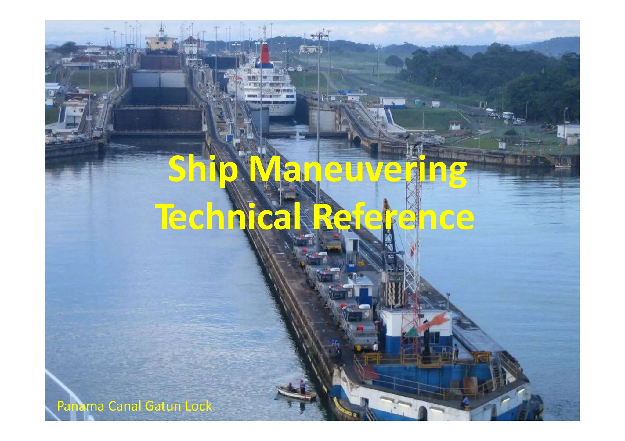
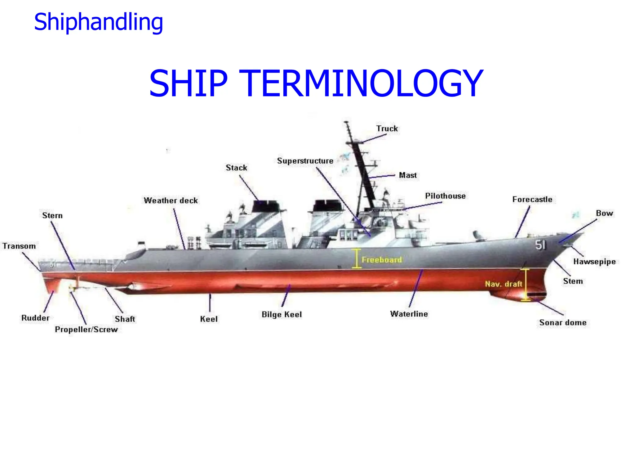
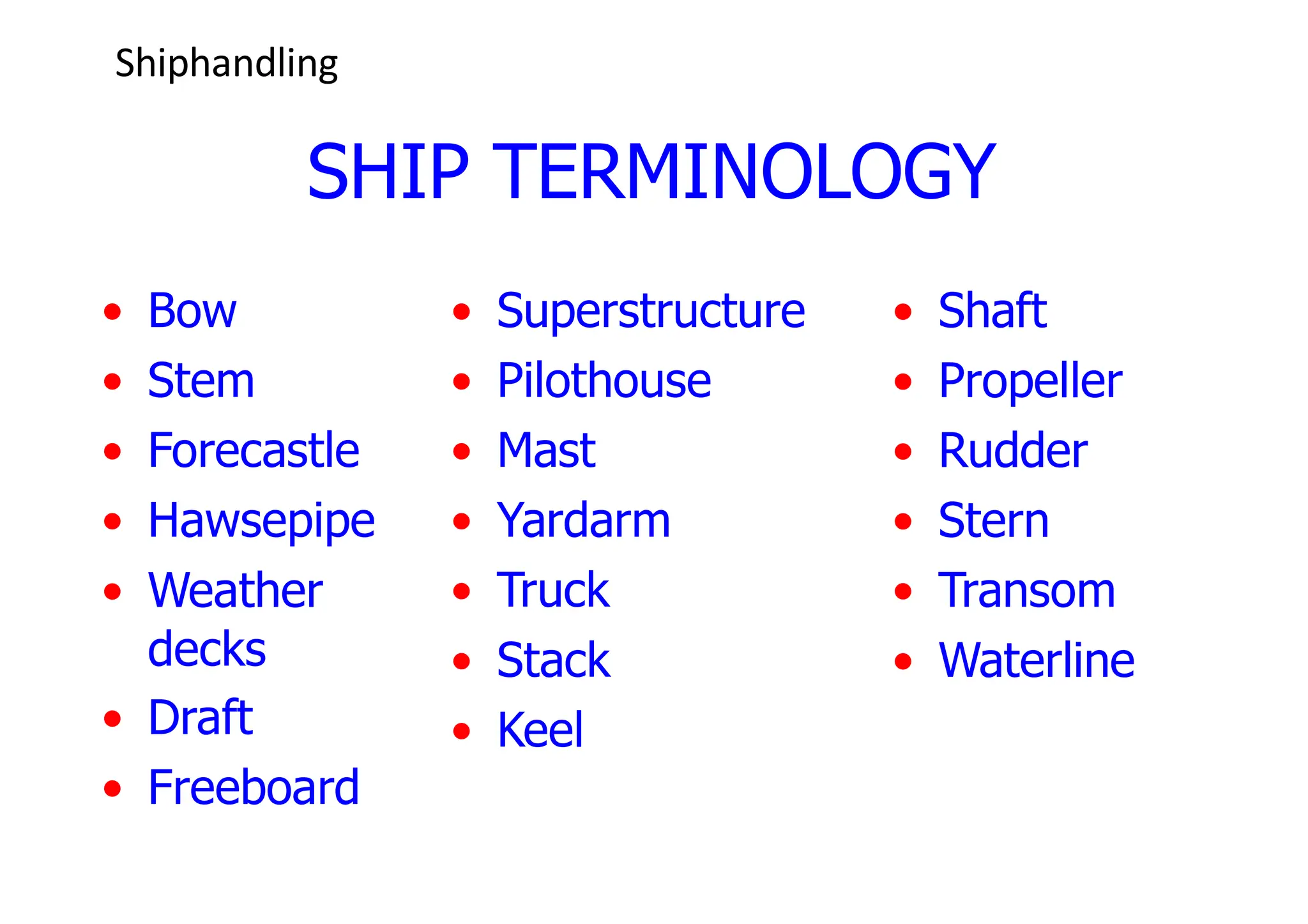
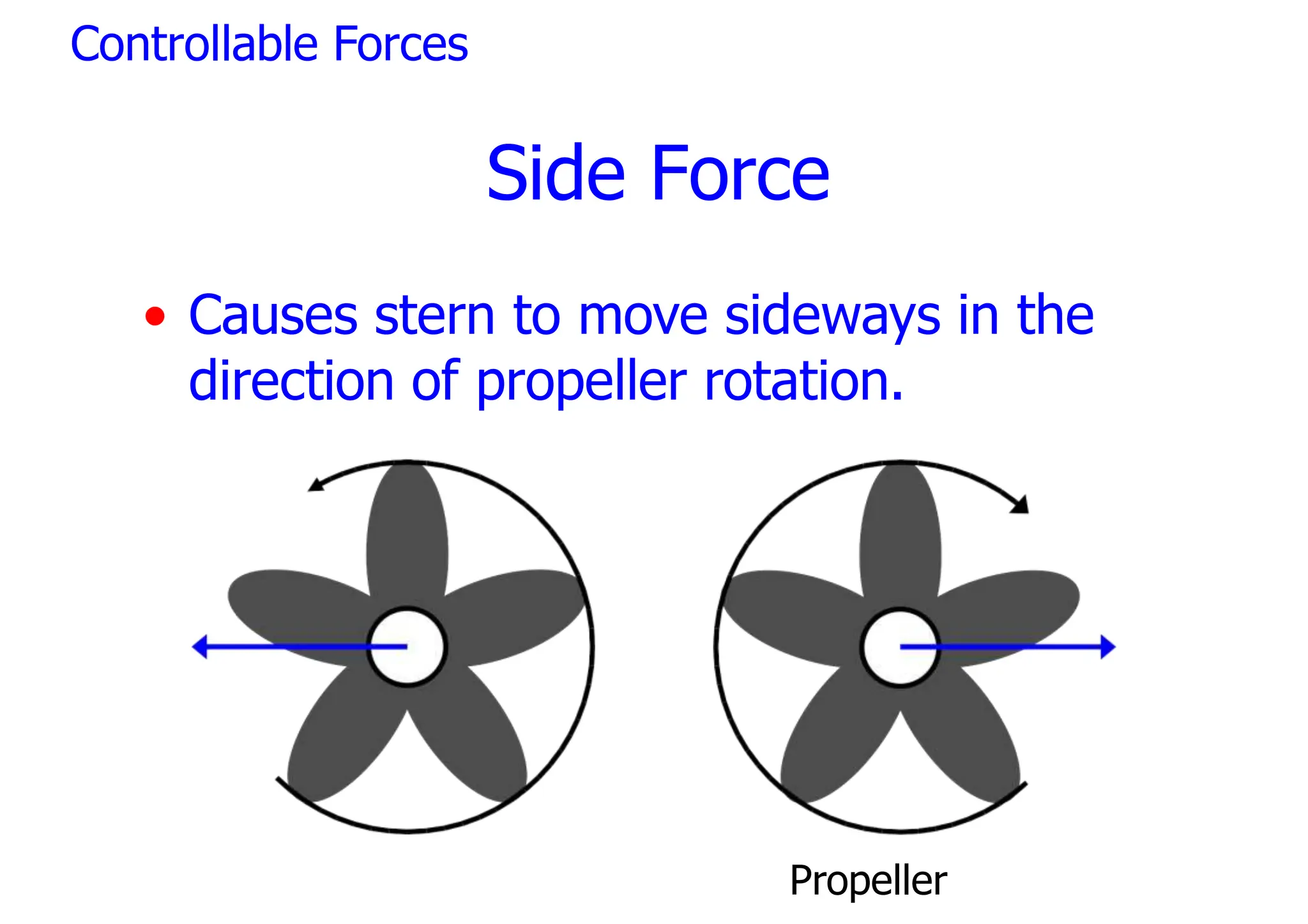
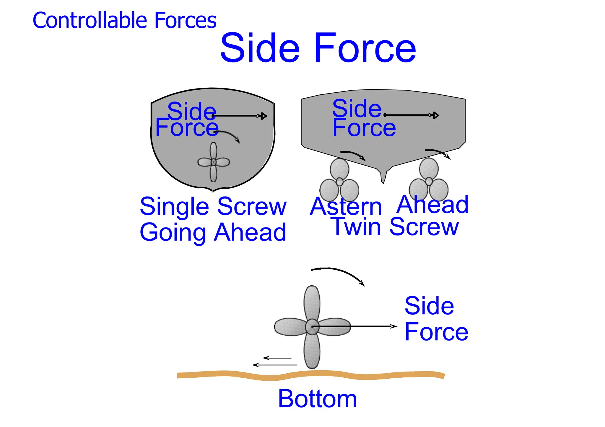
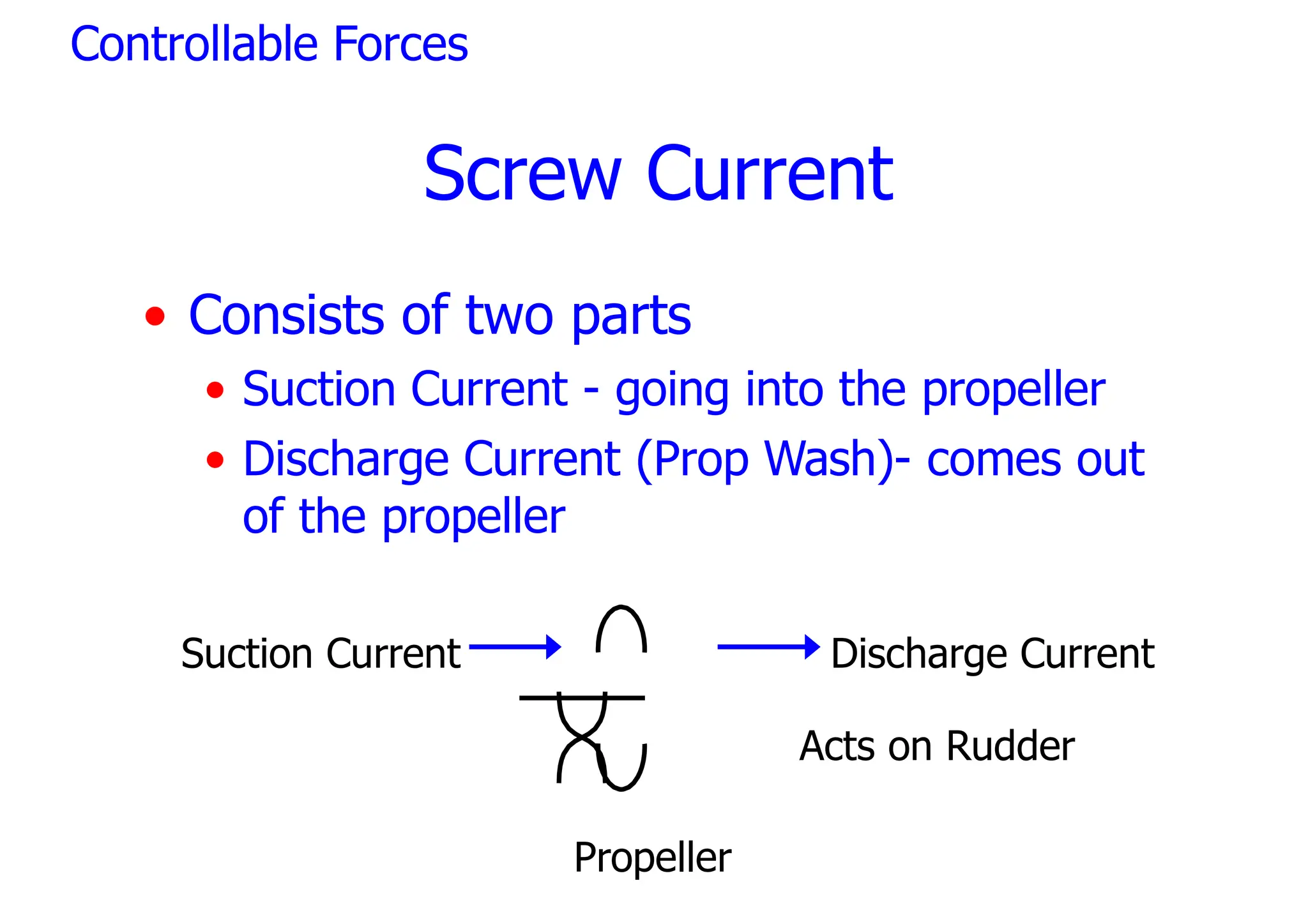
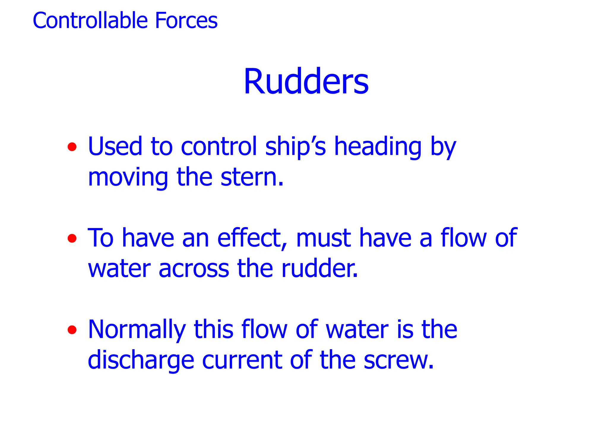
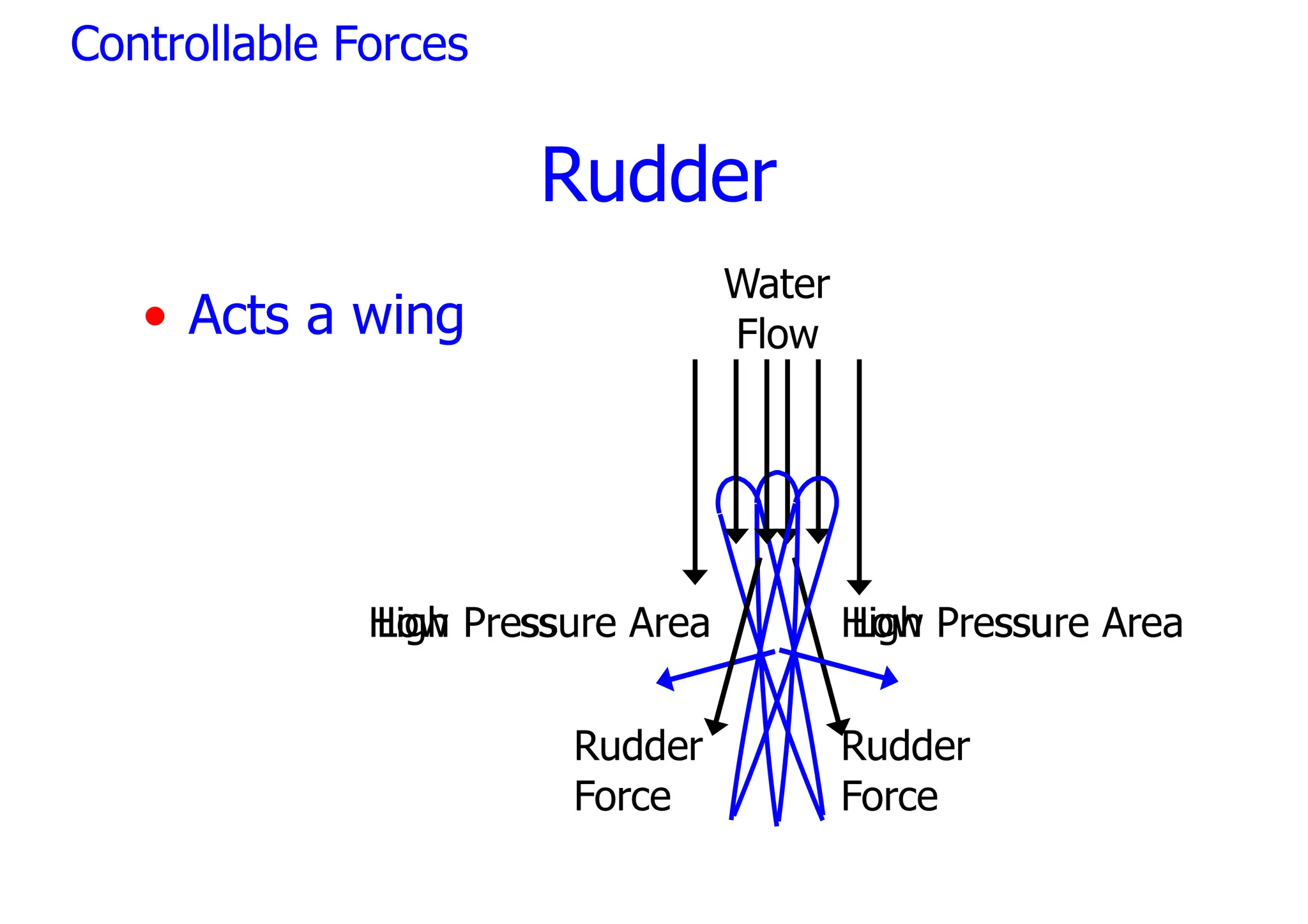
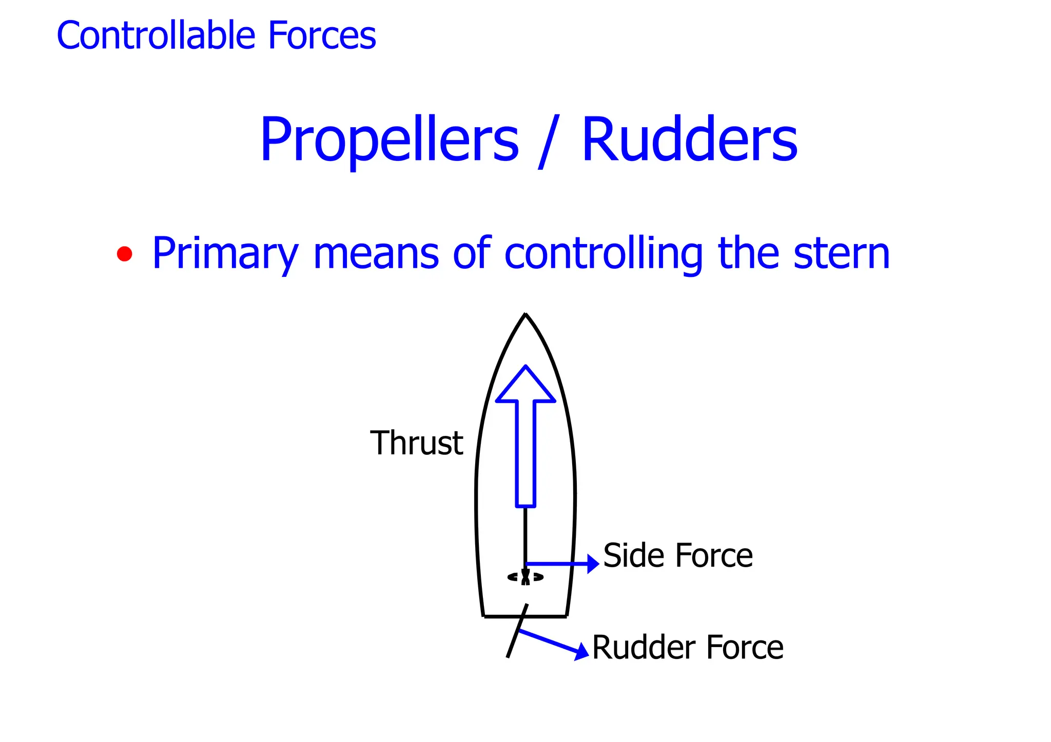
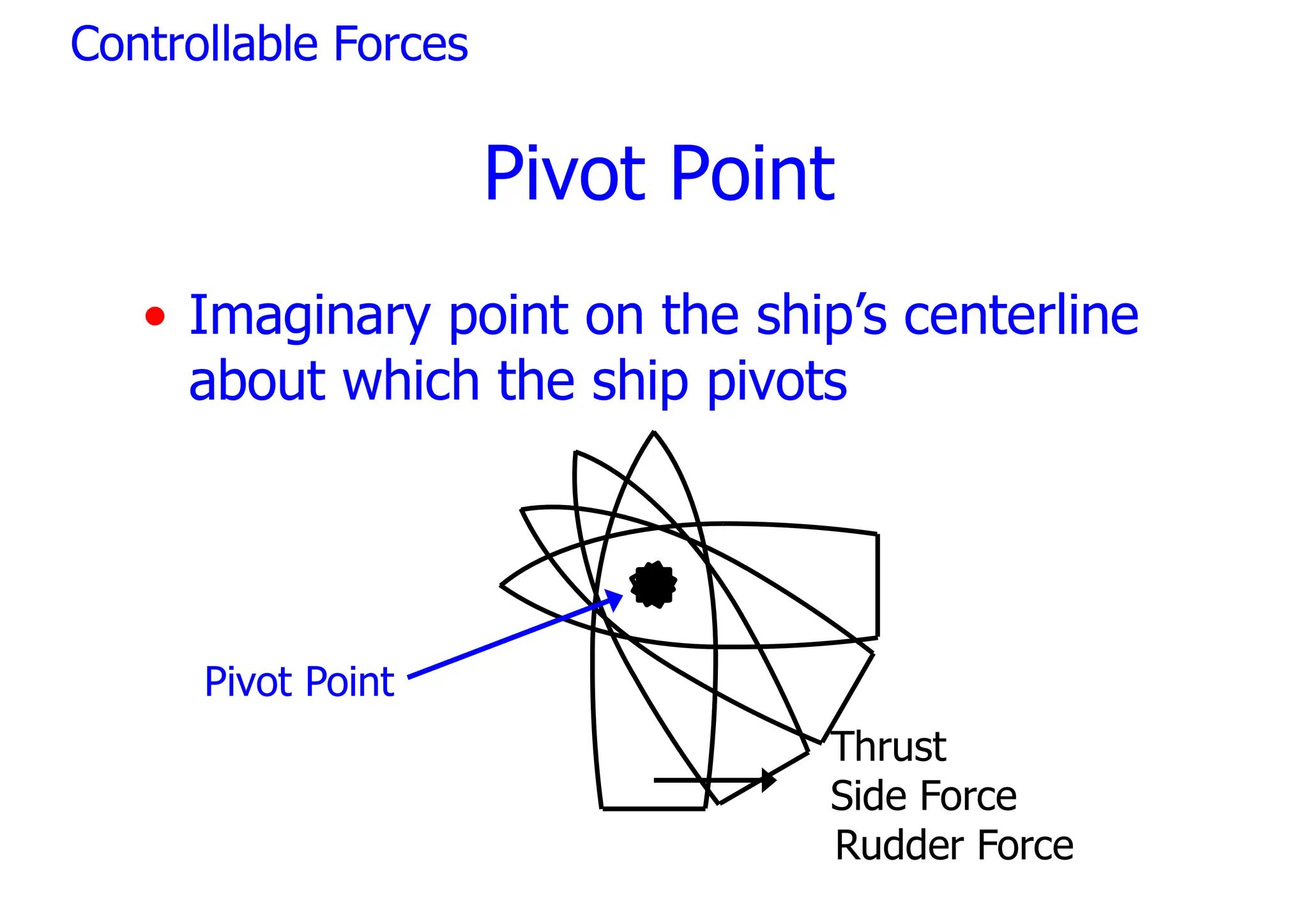
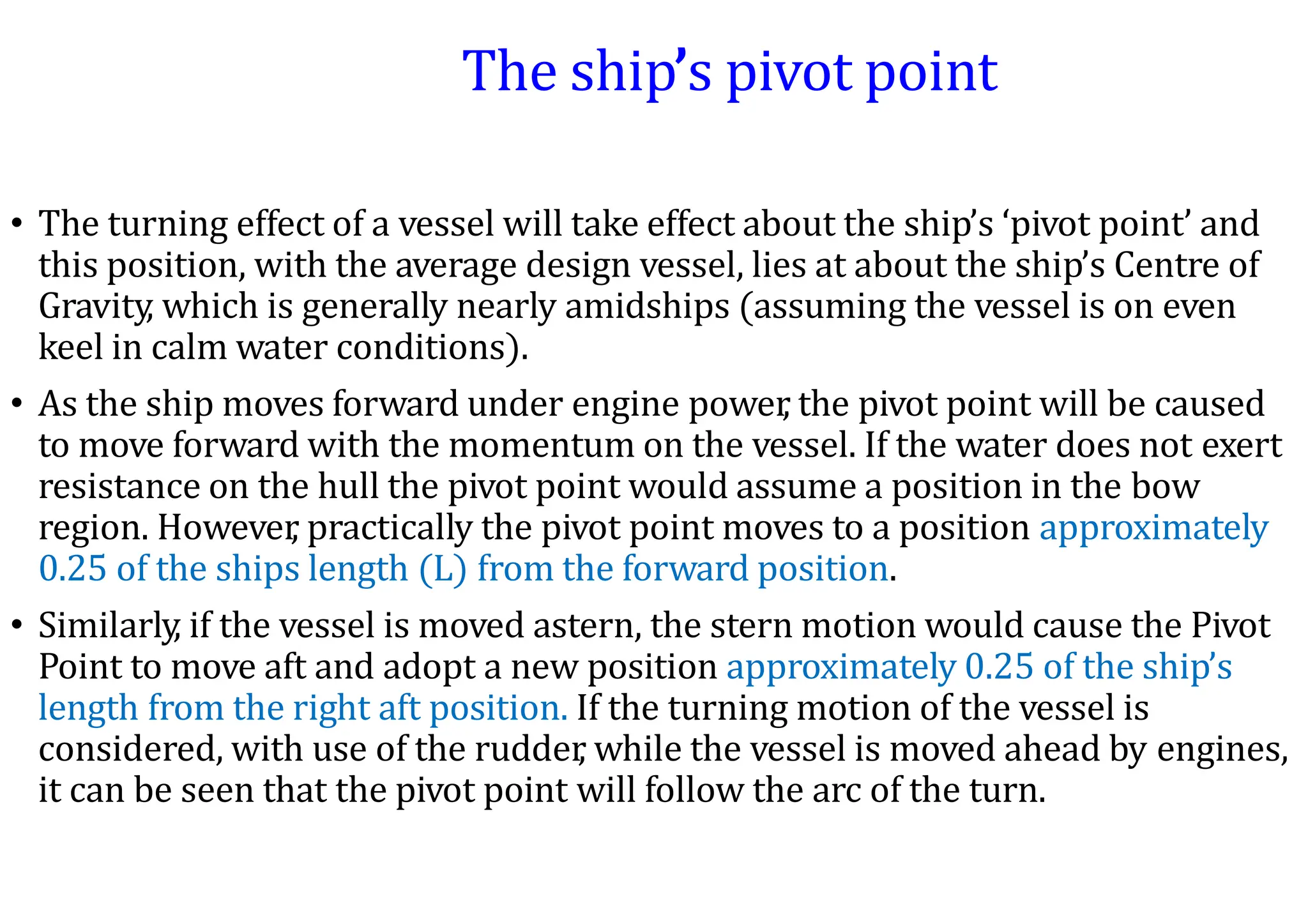
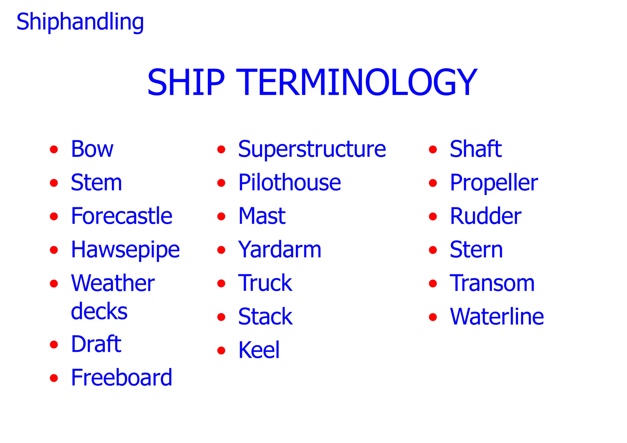
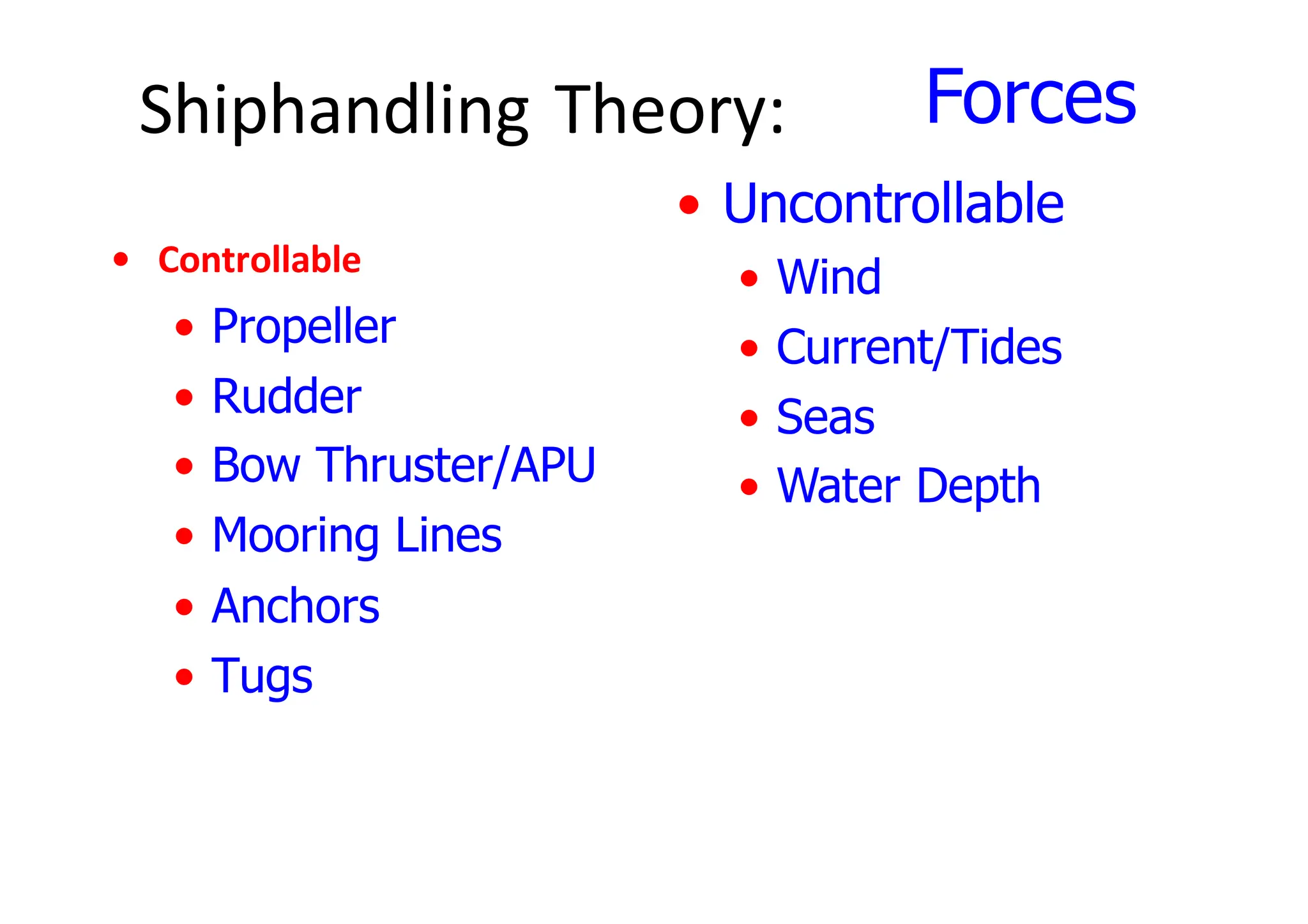
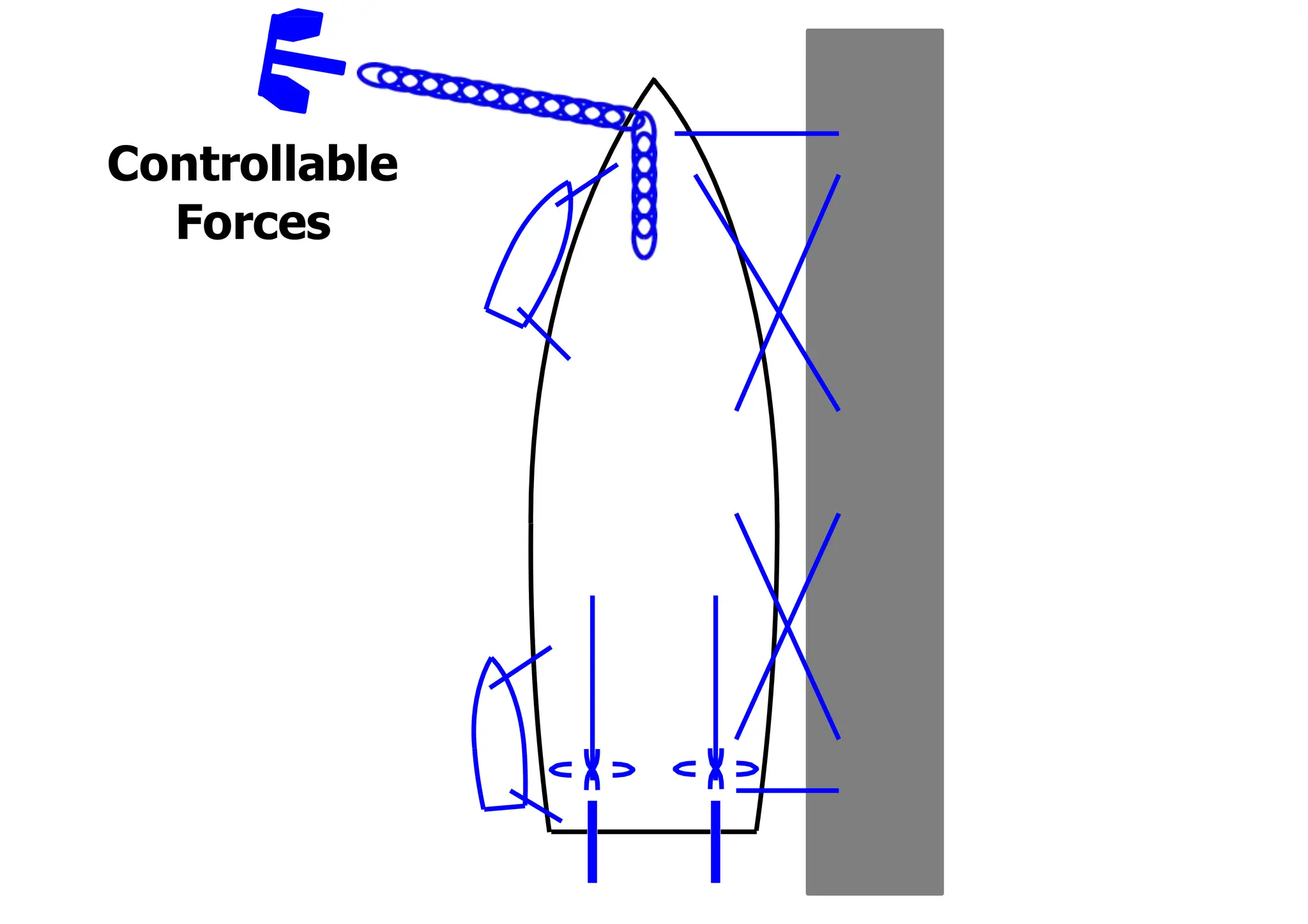
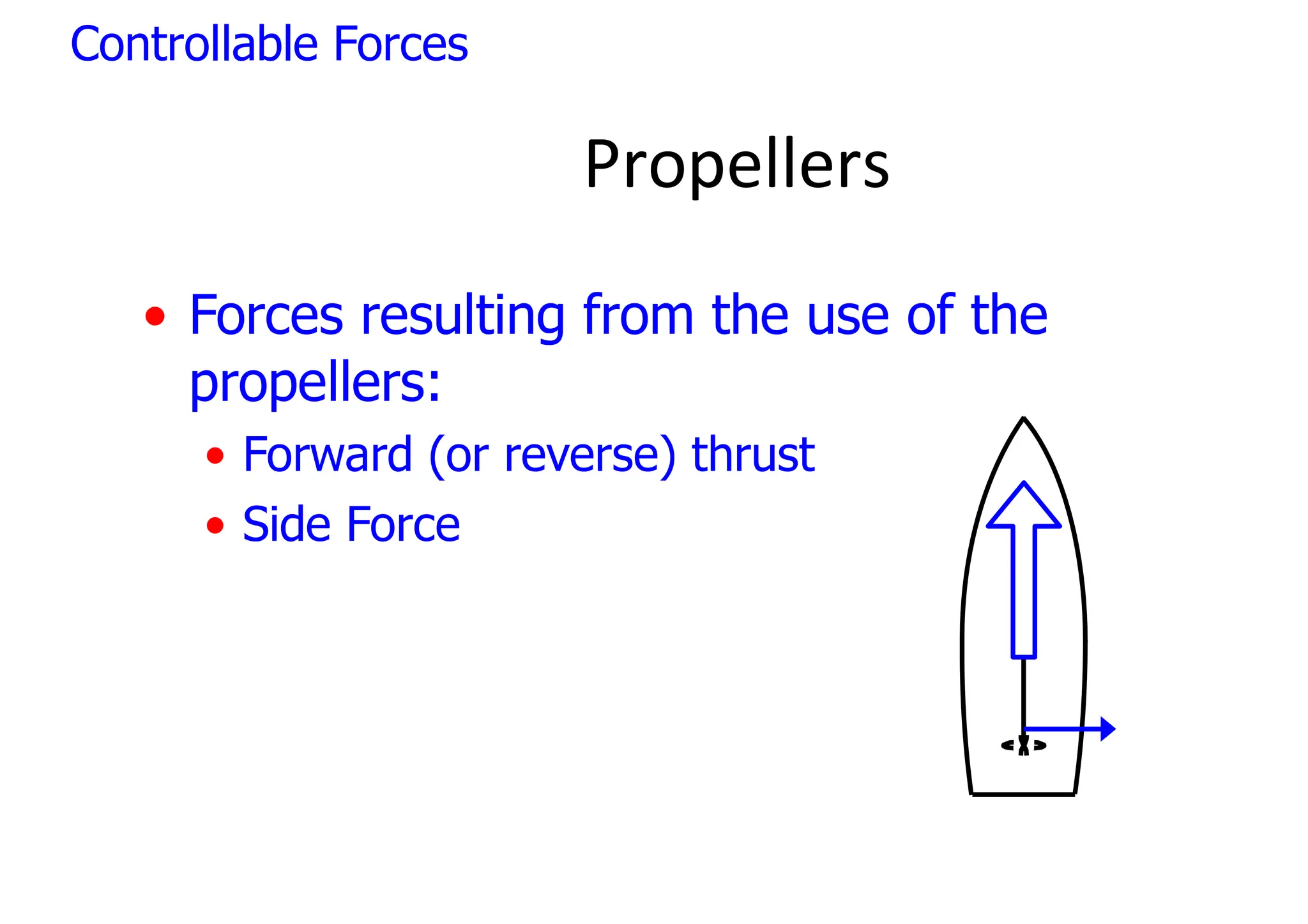
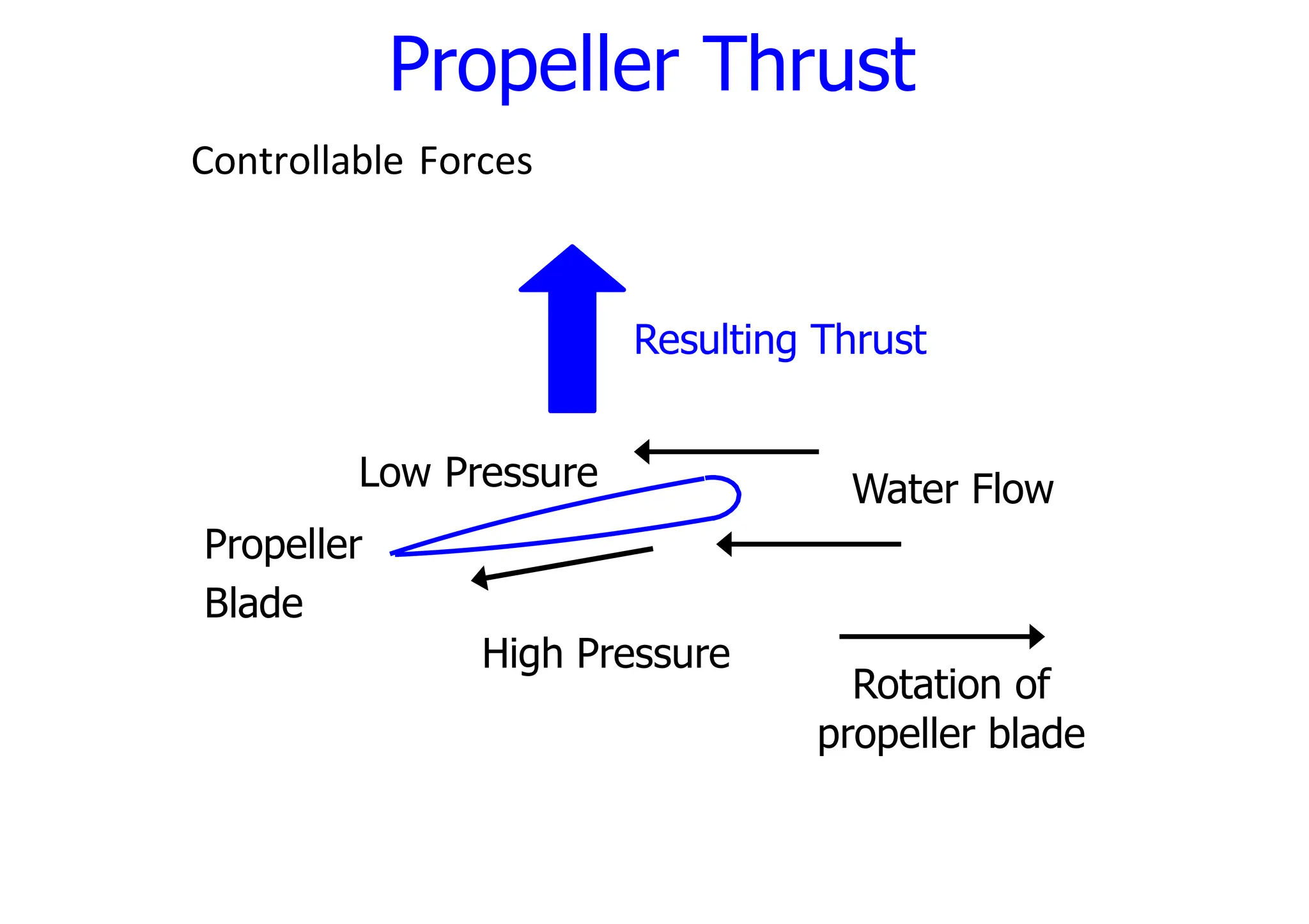
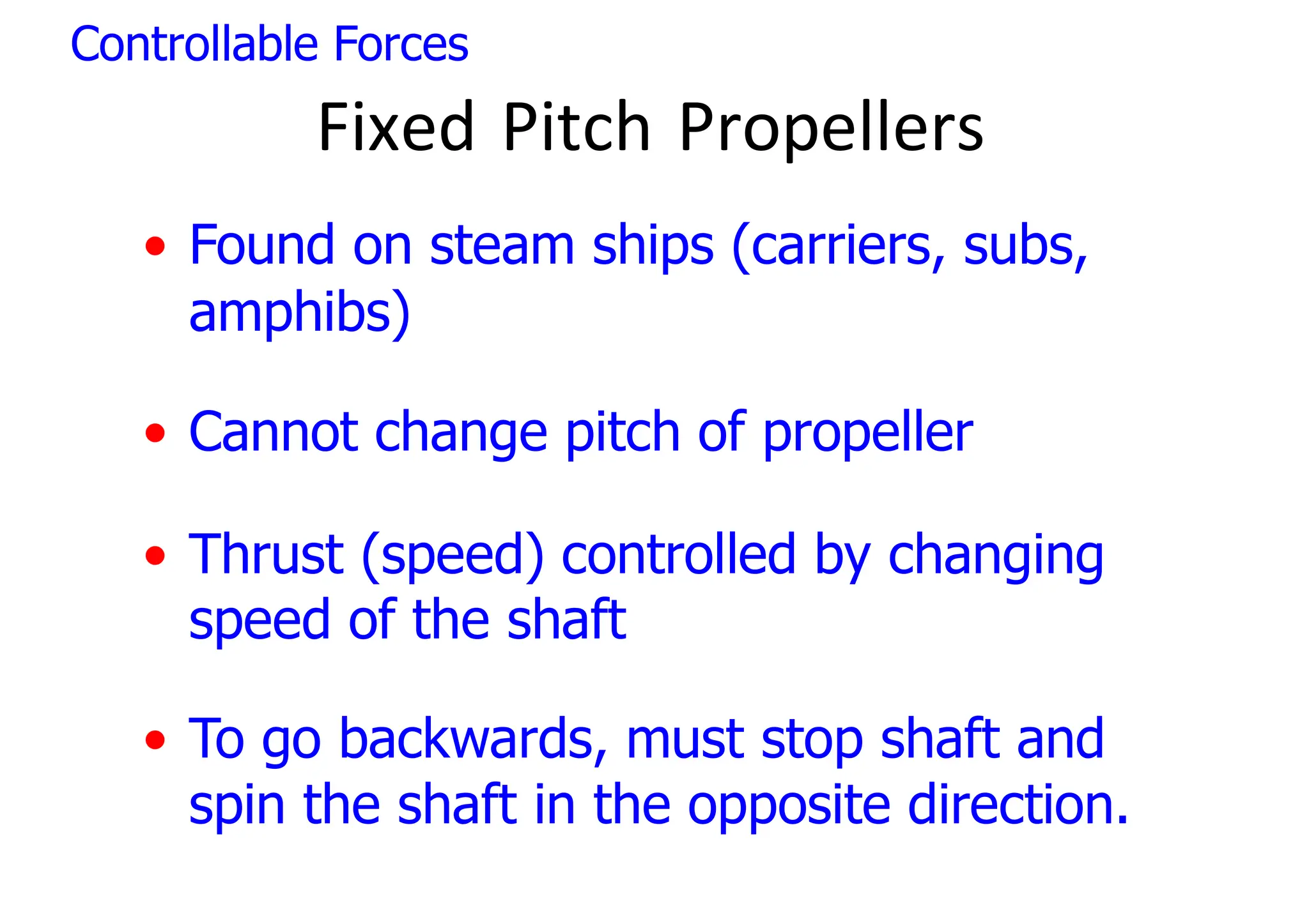
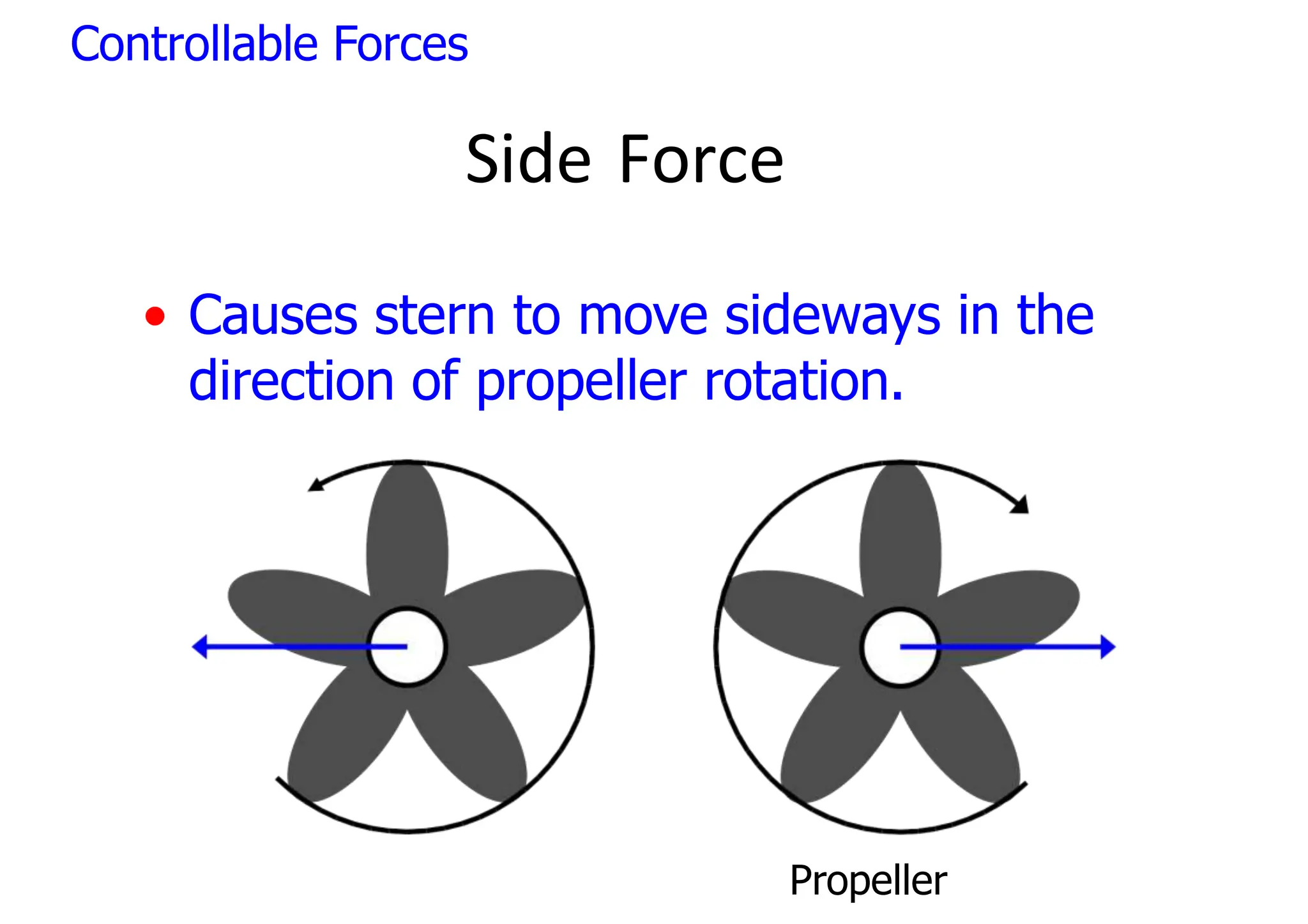
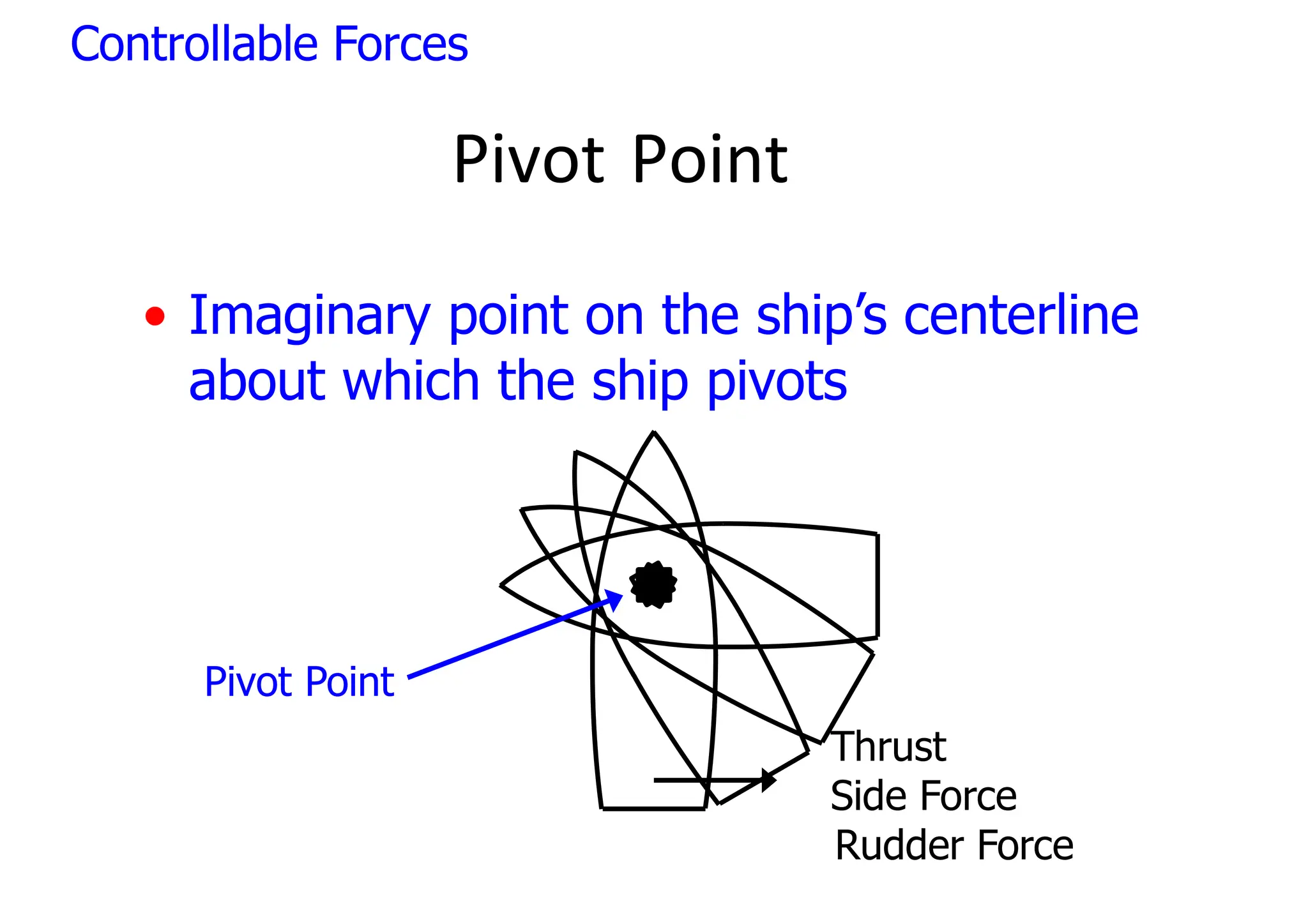
SlideShare a Scribd company logo
1 of 308
Ship Maneuvering
Technical Reference
Panama Canal Gatun Lock
SHIP TERMINOLOGY
Shiphandling
SHIP TERMINOLOGY
• Bow
• Stem
• Forecastle
• Hawsepipe
• Weather
decks
• Draft
• Freeboard
• Superstructure
• Pilothouse
• Mast
• Yardarm
• Truck
• Stack
• Keel
• Shaft
• Propeller
• Rudder
• Stern
• Transom
• Waterline
Shiphandling
Lesson Contents
• Shiphandling Theory
• Laws of Motion
• Controllable Forces
• Uncontrollable Forces
• Shiphandling
• Terminology
• Ground Tackle
• Getting Underway
• Single Screw Characteristics
• Twin Screw Characteristics
• Tug Handling
• Man Overboard Recovery
Shiphandling Theory: Motion
• Various forces acting on the ship create
movement.
• Newton’s Laws of Motion
1.Unless acted upon by an outside force:
• An object in motion tends to stay in motion.
• An object at rest tends to stay at rest.
2.The resulting motion of an object is the
sum of all forces acting on it.
3.Every action has an equal and opposite
reaction.
What is Vessel Handling?
Vessel handling is based on the basic knowledge that a vessel floats
in the water and returns to its original position after a list.
It is maneuvered with the assistance of the rudder, main engine(s)
and other auxiliary equipment, using knowledge of the rolling,
pitching and yawing characteristics of the vessel in waves.
In handling the vessel it is necessary to consider the effects of
environmental conditions while controlling the position of the vessel,
its attitude, and its speed, to move the vessel in the designed
direction in a safe and efficient manner, and to stop at the intended
position.
(Theory and Practice of Ship Handling, Kinzo Inoue, Honorary
Professor, Kobe University).
̎
Ship Handling and Maneuvering
Ship Handling and Maneuvering is defined
as the art of proper control of a ship
while underway, especially in harbors,
around docks and piers. It is one of the skills
that any ship handler finds very
satisfying when well accomplished.
The most basic thing to be understood in
ship handling is to know and anticipate
how a ship behaves under all
circumstances and what orders should be
given in order to make the ship behave and
move exactly the way you want her to. The
difference between the ships’ heading and
the actual direction of movement of the
ship should also be constantly attended to
as this is essentially important at slow
speeds and when there are wind and
current.
Vessel with
Stability
Means
Rudder, main
engine, thrusters,
anchors, mooring
lines, tugs etc.
Vessel
maneuverability
Rolling, Pitching and
Yawing characteristics
in waves
Environmental conditions
*Geography (existence of shallow areas and
water
depth etc.)
* Facilities (port facilities)
* Navigation (buoys, fishing boats, marine traffic
etc.)
* Social (regulations, navigation regulations etc.)
* Nature (wind, tidal flows, visibility, waves etc.)
Ship
Navigator
Control of vessel position, attitude,
and speed for safe and efficient
* movement in the required
direction
* stopping at the required position
Operatevesselas described
̏
Shiphandling Theory: Forces
• Controllable
• Propeller
• Rudder
• Bow Thruster/APU
• Mooring Lines
• Anchors
• Tugs
• Uncontrollable
• Wind
• Current/Tides
• Seas
• Water Depth
Controllable
Forces
Propellers
• Provides the most important source of
force on a ship.
• (Usually) makes ship go forward.
• Most ships have 2 propellers.
• Aircraft carriers / Patrol Craft have 4.
• Frigates have 1.
Controllable Forces
Propellers
• Forces resulting from the use of the
propellers:
• Forward (or reverse) thrust
• Side Force
Controllable Forces
Propeller Thrust
• A result of the propeller spinning on its
shaft.
• Caused by a pressure differential
between the opposite sides of the
propeller blade.
Controllable Forces
Propeller Thrust
Rotation of
propeller blade
Water Flow
Low Pressure
Propeller
Blade
High Pressure
Resulting Thrust
Controllable Forces
Controlling Propeller Thrust
• Depends on type of propellers
• Fixed Pitch Propellers
• Controllable Pitch Propellers
Controllable Forces
Controllable Pitch Propellers
• Found on all gas turbine ships and
some diesel amphibs
• 0 - 12 kts
• shaft rotates at 55 RPM
• thrust (speed) controlled by changing the
pitch of the propeller blade
Controllable Forces
Controllable Pitch Propellers
• >12 kts
• thrust controlled by changing the speed
(RPM) of the shaft.
• The shaft always spins in same
direction whether going forward or
backward.
Controllable Forces
Fixed Pitch Propellers
• Found on steam ships (carriers, subs,
amphibs)
• Cannot change pitch of propeller
• Thrust (speed) controlled by changing
speed of the shaft
• To go backwards, must stop shaft and
spin the shaft in the opposite direction.
Controllable Forces
Side Force
• Causes stern to move sideways in the
direction of propeller rotation.
Propeller
Controllable Forces
Side Force
Astern Ahead
Twin Screw
Side
Force
Bottom
Single Screw
Going Ahead
Side
Force
Side
Force
Controllable Forces
Screw Current
• Consists of two parts
• Suction Current - going into the propeller
• Discharge Current (Prop Wash)- comes out
of the propeller
Suction Current Discharge Current
Acts on Rudder
Propeller
Controllable Forces
Rudders
• Used to control ship’s heading by
moving the stern.
• To have an effect, must have a flow of
water across the rudder.
• Normally this flow of water is the
discharge current of the screw.
Controllable Forces
Rudder
Force
H
Li
o
g
w
h Pres
ss
sure Area H
Lio
gw
h Pres
ss
su
ure Area
• Acts a wing
Rudder
Water
Flow
Rudder
Force
Controllable Forces
Propellers / Rudders
• Primary means of controlling the stern
Thrust
Side Force
Rudder Force
Controllable Forces
Pivot point concept
Pivot Point
• Imaginary point on the ship’s centerline
about which the ship pivots
Pivot Point
Thrust
Side Force
Rudder Force
Controllable Forces
The ship’s pivot point
• The turning effect of a vessel will take effect about the ship’s ‘pivot point’ and
this position, with the average design vessel, lies at about the ship’s Centre of
Gravity, which is generally nearly amidships (assuming the vessel is on even
keel in calm water conditions).
• As the ship moves forward under engine power
, the pivot point will be caused
to move forward with the momentum on the vessel. If the water does not exert
resistance on the hull the pivot point would assume a position in the bow
region. However
, practically the pivot point moves to a position approximately
0.25 of the ships length (L) from the forward position.
• Similarly, if the vessel is moved astern, the stern motion would cause the Pivot
Point to move aft and adopt a new position approximately 0.25 of the ship’s
length from the right aft position. If the turning motion of the vessel is
considered, with use of the rudder
, while the vessel is moved ahead by engines,
it can be seen that the pivot point will follow the arc of the turn.
• If the turning motion of the vessel is considered, with use of the rudder
, while
the vessel is moved ahead by engines, it can be seen that the pivot point will
follow the arc of the turn.
• The combined forces of water resistance, forward of the pivot point and the
opposing turning forces from the rudder
, aft of the pivot point, cause a ‘couple
effect’ to take place. The resultant turning motion on the vessel sees the pivot
point following the arc of the turn.
Pivot point means the center of any rotational system. It is very vital to know the location of
the pivot point as the ship handling depends greatly on knowing the location of the same.
The pivot point is not a fixed point. It changes the location depending on the below
factors;-
▪ When the vessel is at rest or static, the pivot point is almost the same as that of the center
of Gravity, which is denoted by G.
▪ When the vessel moves forward, the position of pivot point shifts forward. The new pivot
point will be about 1/4th of the Length of the vessel from the forward.
▪ When the vessel moves astern, the position of the pivot point shifts towards the stern. The
new pivot point will be about 1/4th of the Length of the vessel from the stern.
• while the vessel moves astern, the pivot point moves towards the stern. This shift of the
pivot point can be made to advantage. Let's assume that both the tugs are pulling with the
same force. Since the pivot point has shifted more towards the stern, the effect of the
Forward tug will be increased automatically. The reason being that the turning lever for the
Forward tug has been increased, because of the shift of the pivot point. Therefore the action
of the forward tug will be dominant over the stern tug. Therefore the bow will move to
PORT
.
The pivot point at anchor
• It should be noted that when the vessel goes to anchor the pivot
point moves right forward and effectively holds the bow in one
position.
• Any forces acting on the hull, such as from wind or currents, would
cause the vessel to move about the hawse pipe position.
• Use of the rudder can however
, be employed when at anchor
, to
provide a ‘sheer’ to the vessel, which could be a useful action
to angle the length of the vessel away from localized dangers.
Pivot Point
Ship twisting with no way on.
Controllable Forces
Pivot Point
• Usually located 1/3 the length of the
ship from the bow. (Just behind the
bridge.)
• Pivot point is not fixed
Controllable Forces
Forces which affect
location of the Pivot Point
• Headway or Sternway
• Ship’s Speed
• Anchors
• Mooring Lines
• Tugs
Controllable Forces
Wind
• Acts on the sail area of the ship
• Exposed superstructure
• Hull structure
• Ships tend to back into the wind
• 30kts of wind = 1kts of current
Current
• Acts on the underwater part of the ship.
• Creates set and drift.
Uncontrollable Forces
Depth of Water
• Squat - Occurs a high speeds
• bow of a ship rides up onto the bow wave
• stern of a ship tends to sink
• Shallow water effects.
Uncontrollable Forces
SHIP TERMINOLOGY
• Bow
• Stem
• Forecastle
• Hawsepipe
• Weather
decks
• Draft
• Freeboard
• Superstructure
• Pilothouse
• Mast
• Yardarm
• Truck
• Stack
• Keel
• Shaft
• Propeller
• Rudder
• Stern
• Transom
• Waterline
Shiphandling
• Headway
• moving forward thru the water
• Sternway
• moving backwards thru the water
• Bare Steerageway
• the minimum speed a ship can proceed
and still maintain course using the rudders
Shiphandling: Terms
• Stand by lines
• Take in the slack
• Take a strain
• Heave around
• Avast heaving
• Hold
• Check
• Double up
• Single up
• Take in
• Slack
• Ease
• Take to the capstain
Ground Tackle, Mooring Lines
Sequence:
Commands:
Shiphandling:
Safety
• Battle dress
• Snap back zone
• Tugs
• Pilots ladder
Shiphandling: Ground Tackle, Mooring Lines
Lesson Contents
• Shiphandling Theory
• Laws of Motion
• Controllable Forces
• Uncontrollable Forces
• Shiphandling
• Terminology
• Ground Tackle
• Getting Underway
• Single Screw Characteristics
• Twin Screw Characteristics
• Tug Handling
• Man Overboard Recovery
Shiphandling Theory: Motion
• Various forces acting on the ship create
movement.
• Newton’s Laws of Motion
1.Unless acted upon by an outside force:
• An object in motion tends to stay in motion.
• An object at rest tends to stay at rest.
2.The resulting motion of an object is the
sum of all forces acting on it.
3.Every action has an equal and opposite
reaction.
Shiphandling Theory: Forces
• Controllable
• Propeller
• Rudder
• Bow Thruster/APU
• Mooring Lines
• Anchors
• Tugs
• Uncontrollable
• Wind
• Current/Tides
• Seas
• Water Depth
Controllable
Forces
Propellers
• Provides the most important source of
force on a ship.
• (Usually) makes ship go forward.
• Most ships have 2 propellers.
• Aircraft carriers / Patrol Craft have 4.
• Frigates have 1.
Controllable Forces
Propellers
• Forces resulting from the use of the
propellers:
• Forward (or reverse) thrust
• Side Force
Controllable Forces
Propeller Thrust
• A result of the propeller spinning on its
shaft.
• Caused by a pressure differential
between the opposite sides of the
propeller blade.
Controllable Forces
Propeller Thrust
Rotation of
propeller blade
Water Flow
Low Pressure
Propeller
Blade
High Pressure
Resulting Thrust
Controllable Forces
Controlling Propeller Thrust
• Depends on type of propellers
• Fixed Pitch Propellers
• Controllable Pitch Propellers
Controllable Forces
Controllable Pitch Propellers
• Found on all gas turbine ships and
some diesel amphibs
• 0 - 12 kts
• shaft rotates at 55 RPM
• thrust (speed) controlled by changing the
pitch of the propeller blade
Controllable Forces
Controllable Pitch Propellers
• >12 kts
• thrust controlled by changing the speed
(RPM) of the shaft.
• The shaft always spins in same
direction whether going forward or
backward.
Controllable Forces
Fixed Pitch Propellers
• Found on steam ships (carriers, subs,
amphibs)
• Cannot change pitch of propeller
• Thrust (speed) controlled by changing
speed of the shaft
• To go backwards, must stop shaft and
spin the shaft in the opposite direction.
Controllable Forces
Side Force
• Causes stern to move sideways in the
direction of propeller rotation.
Propeller
Controllable Forces
Side Force
Astern Ahead
Twin Screw
Side
Force
Bottom
Single Screw
Going Ahead
Side
Force
Side
Force
Controllable Forces
Screw Current
• Consists of two parts
• Suction Current - going into the propeller
• Discharge Current (Prop Wash)- comes out
of the propeller
Suction Current Discharge Current
Acts on Rudder
Propeller
Controllable Forces
Rudders
• Used to control ship’s heading by
moving the stern.
• To have an effect, must have a flow of
water across the rudder.
• Normally this flow of water is the
discharge current of the screw.
Controllable Forces
Rudder
Force
Hliog wh Pres
ss
sure Area HLiogwh Pressssuure
Area
• Acts a wing Rudder Water
Flow
Rudder
Force
Controllable Forces
Propellers / Rudders
• Primary means of controlling the stern
Thrust
Side Force
Rudder Force
Controllable Forces
Pivot Point
• Imaginary point on the ship’s centerline
about which the ship pivots
Pivot Point
Thrust
Side Force
Rudder Force
Controllable Forces
Pivot Point
Ship twisting with no way on.
Controllable Forces
Pivot Point
• Usually located 1/3 the length of the
ship from the bow. (Just behind the
bridge.)
• Pivot point is not fixed
Controllable Forces
Forces which affect
location of the Pivot Point
• Headway or Sternway
• Ship’s Speed
• Anchors
• Mooring Lines
• Tugs
Controllable Forces
Internal and External Factors
Internal Factors/Forces
These are the factors or forces INSIDE the ship that affects how the
vessel behaves or performs during maneuvering, some examples are:
Engine Power, Specification of Propeller and Rudder, Mooring Lines
and Anchor, Thrusters and Vessel Speed.
External Factors/Forces
These are the factors or forces that happens OUTSIDE the ship
that affects the maneuvering of the vessel while underway,
approaching a port or being docked, some examples are:
Tide, A sudden change in wind velocity and direction (gust), Set and
drift, The proximity of other vessels, The depth of harbors.
External Factors/forces
● Tide - At low tide, the water will be
too shallow for the ship to move and
she will hit the bottom of the harbor.
This means that ships need to
schedule their arrival at or departure
from some ports around the high
tides at those ports. Ships' mooring
lines tighten as the tide rises, and
slacken when the tide goes out. High
tides help in navigation. They raise
the water level close to the shores.
This helps the ships to arrive at
harbor more easily.
● A sudden change in wind
velocity and direction (gust) -
The Wind Force will develop a
sideways force on the vessel,
away from the exposed side.
Making Headway with Stern to
Wind, the vessel loses “course
stability” and is difficult to steer,
this effect is greater when there
is also a following Sea or Swell.
● Set and drift - Ignoring set and
drift can cause a mariner to get
off their desired course,
sometimes by hundreds of miles.
A mariner needs to be able to
steer the ship and compensate
for the effects of set and drift
their vessel while
upon
underway. The actual course a
vessel travels is referred to as
the course over the ground.
● The proximity of
other vessels
● The depth of harbors -
Shallow water affects the
maneuverability of ships
limited
considerably. The
water depth will change the
pressure distribution
around the vessel and lead
to an increase in
hydrodynamic forces.
Internal Factors/forces under the control of the
Shiphandler
● Engine power
challenging to
keeping control.
- It can be
slow down while
This is because
reduction in propeller speed reduces
water flow over the rudder and the
rudder becomes less effective. The
conventional approach for halting is
to put engines astern. The ship will
be less responsive to steering when
a propeller is rotating astern because
the water flow across the rudder is
disrupted. In addition, there is the
disruptive effect of transverse thrust.
● Speed - The turning circle will
not increase by any
therefore
considerable margin with an increase
in speed, because the steering effect
is increased over the same period.
Generally speaking, higher speeds
mean more force on the rudder but
also more momentum. So, the head
will turn faster, but the ship will travel
farther along its previous track. The
higher momentum also means more
heeling.
● Effect of the type of propeller -
Propeller affects every phase of
performance - handling, riding,
comfort,
engine
safety.
speed, acceleration,
life, fuel economy and
In boat
are
determining
propellers
performance,
second in importance only to the
power available from the engine
itself. Without the propeller's
thrust, nothing happens.
● Rudder movement and type -
The rudder acts as a hydrofoil.
By itself, it is a passive
instrument and relies on water
passing over it to give it ‘lift’.
Rudders are placed at the stern
of a ship for this reason and to
take advantage of the forward
pivot point, which enhances the
effect.
● Thrusters - The thruster takes
suction from one side and throws
it out at the other side of the
vessel, thus moving the ship in
the opposite direction. This can
be operated in both the
directions, i.e., port to starboard
and starboard to port. The bow
thrusters are placed below the
waterline of the ship.
● Anchors and mooring lines - The
purpose of an anchor is to keep a ship
safe and secure at a desired location or
to help control the ship during bad
weather. However, to accomplish these
vital purposes, just having an anchor is
not enough. The anchor must be solid,
dependable, and used properly at the
right time and place. On the other hand,
an anchor mooring fixes a vessel's
position relative to a point on the bottom
of a waterway without connecting the
vessel to shore. As a verb, mooring refers
to the act of attaching a vessel to a
mooring.
● Tugboats - Tugboats are
small,
capable
powerful boats
large
of steering
ships by pulling or pushing
them. They are used to
assist these ships in places
where they are unable to
maneuver themselves,
such as narrow water
channels and ports.
Wind
• Acts on the sail area of the ship
• Exposed superstructure
• Hull structure
• Ships tend to back into the wind
• 30kts of wind = 1kts of current
Current
• Acts on the underwater part of the ship.
• Creates set and drift.
Uncontrollable Forces
Depth of Water
• Squat - Occurs a high speeds
• bow of a ship rides up onto the bow wave
• stern of a ship tends to sink
• Shallow water effects.
Uncontrollable Forces
Three Types of Basic Ship Motion
1. Longitudinal motion (forward or astern).
2. Lateral motion (sideways).
3. Rotational or turning motion.
SHIP FACTORS THAT AFFECT MANUEVERING
● Handling characteristics will vary from ship type to ship
type and from ship to ship. Handling qualities are
determined by ship design, which in turn depends on
the ship’s intended function. Typically, design ratios,
such as a ship’s length to its beam, determine its
willingness to turn.
● However, desirable handling qualities are achieved
only when there is a balance between directional
stability and directional instability.
Other Variable factors affecting ship
handling.
● Human factor – A delay in time
between your given order and the
execution of the order will affect how
you intend to move your ship. This
is caused by human factors
because the individuals you are
ordering may have different
responses depending on their training
and ability to perform the job, or that
orders have to be relayed by an
officer to the helmsman, which is a
bad practice that should be avoided
so that the conning officer should be
able to give his orders directly to the
helmsman.
● Wind and current are usually associated as both being
forces not under control of the shiphandler. The two
forces have, however, a different effect on the ship
because of the difference in nature of the two. When the
ship is affected by wind alone and moves through the
water, the hull meets underwater resistance. When, on the
other hand, the ship’s motion originates from current,
there is practically no resistance of the above-water area
to air. As water is eight hundred times denser than sea
level atmosphere, current must,
than
by nature, have
wind, especially on
considerably stronger effect
loaded ships.
OCEAN CURRENT
Ocean currents are the continuous, predictable, directional
movement of seawater driven by gravity, wind (Coriolis
Effect), and
directions:
movements
water density. Ocean water moves in two
horizontally and vertically. Horizontal
are referred to as currents, while vertical
changes are called upwellings or downwelling.
Ocean currents act much like a conveyor belt, transporting
warm water and precipitation from the equator toward the
poles and cold water from the poles back to the tropics.
● Current has a direct effect on the under-
water part of the ship and an indirect ef-
fect expressed in momentum after the
ship alters course or comes out of a cur-
rent, when the ship will carry momentum
in the direction of the current that the
ship was previously subjected to.
Effect of Wind and Current
● Whereas the effect of wind on the ship has to be
considered with respect to the pivot point, current
affects a freely moving ship as a whole and
consequently its effect is on the center of gravity.
However, when we try to keep the ship stationary relative
to the ground, we must arrest the ship’s movement and
let the ship make speed through the water contrary to
the current, in which case the ship meets underwater
resistance.
● All freely moving ships, not being subjected to wind and
dead in the water, have the same speed as the current,
whether the ships are big or small, loaded or light. Ships
not freely moving, as ships at anchor or moored, are
subjected to pressure exerted by the current, pressure
which is directly proportionate to the exposed underwater
area and to the square of the current velocity.
● In a strong tide we see that ships at
anchor, or moored to a single point, are
heading into the tide; when it is nearly
slack water ballasted ships will be more
affected by wind while the loaded tankers
still remain heading into the tide.
● When we approach the monobuoy with a
ballasted tanker in wind and tide condition,
the direction of the loaded tankers,
moored on single points nearby, gives
us an indication of the direction of the
current. However, the heading of the
ballasted ship, after having been tied up
to the buoy, may be quite different from
the heading of the loaded ship
Wind
Vessels such as Container and Ro-Ro Ships have large
freeboard and are thus more affected by winds. This exposed
area of the ship is also known as windage area as the effect of
wind is more prominent over it.
The wind effect on the same ship will be different at different
places, depending upon the draught condition of the ship. A wind
with force of 3-4 on the Beaufort scale will have similar effect in
light condition as with wind force of 7-8 when the ship is down to
her marks.
When ship is at slow speeds during maneuvering or near to the
coast, wind direction is easy to find; but this is not the case when
out at high sea. The direction of the wind perceived when
standing on deck is its relative direction. This is the resultant of
the true direction of the wind and the course steered by the ship.
EFFECT OF WIND
● Needless to say, with no tug assistance, it is wise to get
this area of ship handling right first time and also
appreciate what the limits are.
Navigators can use the wind:
1. As a good brake
2. As a device for making a tight turn.
3. To maneuver comparatively easily as long as the wind remains
about two to three points on the bow.
Vessel Stopped
● we have a ship on even keel, stopped dead in the
water. It has the familiar all aft accommodation
and we will assume, at this stage, that the wind is
roughly on the beam.
● Whilst the large area of superstructure and
funnel offer a considerable cross-section to the
wind, it is also necessary to take into account the
area of freeboard from forward of the bridge to the
bow. On a VLCC this could be an area as long as
280 x 10 meters.
● The center of effort of the wind (W) is thus
acting upon the combination of these two areas
and is much further forward than is sometimes
expected. This now needs to be compared with the
underwater profile of the ship and the position of
the pivot point (P).
● With the ship initially stopped in the water this
was seen to be close to amidships. The center of
effort of the wind (W) and the pivot point (P) are
thus quite close together and therefore do not create
a turning influence upon the ship. Although it will
vary slightly from ship to ship, generally
speaking, most will lay stopped with the wind just
forward or just abaft the beam.
Vessel Making Headway
● When the same ship is making headway,
the shift of the pivot point upsets the
previous balance attained whilst stopped,
figure 2. With the wind on the beam, the
center of effort of the wind remains where it
is but the pivot point moves forward. This
creates a substantial turning lever between
P and W and, depending on wind strength,
the ship will develop a swing of the bow into
the wind.
● At lower speeds the pivot point shifts even
further forward, thereby improving the wind's
turning lever and effect. When approaching a
berth with the wind upon or abaft the beam
that as speed is reduced the effect of
the wind gets progressively greater and
requires considerable corrective action.
● When approaching a berth or a buoy with
the wind dead ahead and the ship on an
even keel such an approach should be
easily controlled. Even at very low speeds
the ship is stable and will wish to stay with the
wind ahead until stopped.
Vessel Making Sternway
● The effect of the wind on a ship making sternway is
generally more complex and less predictable. In part this
is due to the additional complication of transverse thrust
when associated with single screw ships.
● Figure 3, we have already seen that with sternway the
pivot point moves aft to a position approximately 1/4
L from the stern. Assuming that the centre of effort (W)
remains in the same position, with the wind still on the
beam, the shift of pivot point (P) has now created a totally
different turning lever (WP). This will now cause the stern to
swing into the wind.
● Some caution is necessary, however, as the turning lever
can be quite small and the effect disappointing, particularly
on even keel. In such cases, the stern may only partially
seek the wind, with the ship making sternway 'flopped'
across the wind. This situation is not helped by the
center of effort (W) moving aft as the wind comes round
onto the quarter. This, in turn, tends to reduce the
magnitude of the turning lever WP.
● The other complicating factor is transverse thrust. If the
wind is on the port beam, there is every likelihood that
the transverse thrust and effect of wind will combine and
indeed take the stern smartly into the wind. If, however, the
wind is on the starboard beam, it can be seen that
transverse thrust and effect of wind oppose each other.
Which force wins the day is therefore very much
dependent upon wind strength versus stern power,
unless you know the ship exceptionally well, there may
be no guarantee as to which way the stern will swing when
backing.
Trim and Headway
● So far we have only considered a ship on even
keel. A large trim by the stern may change
the ship's wind handling characteristics quite
substantially.
● Figure 4 shows the same ship, but this time
in ballast and trimmed by the stern. The
increase in freeboard forward has moved W
forward and very close to P. With the
turning lever thus reduced the ship is not so
inclined to run up into the wind with headway,
preferring instead to fall off, or lay across the
wind. Because the ship is difficult to keep
head to wind, some pilots will not accept a
ship that has an excessive trim by the
stern, particularly with regards SBM
operations.
Vessel Head to Wind with
Headway
● The middle diagram in Figure 6 shows a vessel making
Headway through the water, and Heading directly into the
Wind. W is now well forward of amidships, and in fact very
close to P; the wind is exerting no turning moment, or
sideways force, on the vessel. A comparatively small
change in relative wind direction (either by alteration of
course, or wind fluctuation), will place the wind on the
vessel's bow; the whole of one side of the vessel will now
be exposed to the wind, and W will move aft as shown in
the side diagrams of Figure 6. The following effects will now
be experienced:-
● a) The Turning Force will now develop a turning moment
about P, tending to turn the vessel into the wind again.
● b) The Wind Force will also develop a sideways force on
the vessel, away from the exposed side.
● Head to Wind therefore, the vessel is "course stable",
provided that she maintains Headway through the water.
● If the ship has a large Trim by the stern W will be further
forward, with a reduction, or even loss, of "course stability".
This can sometimes result in a rapid and violent loss of
control.
Vessel Head to Wind with
Sternway.
● Consider the situation when our vessel remains Head to
Wind, but now starts to make Sternway through the water.
W remains forward, whilst P has moved aft, as shown in the
middle diagram of figure 7: the wind is exerting no turning
moment or sideways force.
● A comparatively small change in the relative direction of the
wind will move W aft, as shown in the side diagrams of
Figure 7: however P remains aft of W. The following
effects will now be experienced:-
● a) The Wind Force will develop a strong turning moment
about P, tending to turn the vessel's bow further away from
the wind.
● b) The Wind Force will develop a sideways force on the
vessel, away from the exposed side.
● Head to Wind, as soon as the vessel starts to make
Sternway through the water, she loses "course stability"
and the bow will pay off away from the wind, sometimes
quite rapidly.
● If the ship has a large Trim by the stern W may move
further forward, perhaps quickly, and the loss of "courses
stability" is even more pronounced. This can sometimes
result in a rapid and violent loss of control.
Vessel Stern to Wind with
Headway
● The middle diagram of figure 8 shows a vessel making
Headway through the water, and with the Wind directly
Astern. P is forward, a long distance from W, which is well
aft. A comparatively small change in relative wind direction
will move W forwards as shown in the side diagrams of
Figure 8: however W is still some distance abaft P. The
following effects will now be experienced:-
● a) The Wind Force will develop a strong turning moment
about P, tending to turn the vessel's Stern further away
from the Wind.
● b) The Wind Force will develop a sideways force on the
vessel, away from the exposed side.
● Making Headway with Stern to Wind, the vessel loses
"course stability" and is difficult to steer, this effect is greater
when there is also a following Sea or Swell.
● If the ship has a large Trim by the Stern, W may move
further forward, and loss of "course stability" may be
generally less pronounced, but still a potential danger.
Vessel Stern to Wind making Sternway
● The middle diagram of Figure 9 shows a
vessel making Sternway through the water,
and with the Wind directly Astern. P has
moved aft, fairly close to W, which remains
even further aft. A change in relative wind
direction will eventually move W forward of
P, as shown in the side diagrams of Figure
9, with the following effects:-
● a) The Wind Force will develop a turning
moment about P, tending to turn the vessel's
Stern back into the Wind.
● b) The Wind Force will develop a sideways
force on the vessel, away from the exposed
side.
● Making Sternway through the water, with Stern
to Wind, the vessel is again "course stable".
● If the ship has a large Trim by the Stern
W may move further forward, generally
improving "course stability"; however with
such a Trim, there is always the possibility of
an unpredictable loss of control.
Wind force
● Wind force depends on- windage,
wind velocity (wind pressure),
the angle between apparent
wind, and heading. Wind
pressure is proportional to wind
velocity squared.
● The Centre of wind pressure
depends on the distribution of
windage alongside the ship.
Ship in a beam wind
● Ship stopped
● The wind force is large.
● There is no longitudinal component.
● The behavior of the ship depends on
the center of wind pressure, which
could be in front of or behind the point
of application of transverse resistance
force (pivot point). This point is
approximately at midship.
● Ship is drifting and turning either way,
depending on the
relative position of these points.
Ship with headway
● Point of application of wind force is
behind the pivot point.
● Ship has tendency to swing
towards the wind line.
Ship with sternway
● Point of application of wind
force is in front of the pivot
point.
● Ship has tendency to swing
out of the wind line.
Wind from bow quarter
● Ship with headway
● The point of application of wind
force is behind the pivot point.
● The ship has a tendency to swing
towards the wind line.
Ship with sternway
● Point of application of
wind force is behind the
pivot point.
● Ship
swing
line.
has tendency to
towards the wind
QUESTION:
WHAT ARE
THE
FORCES
INA TURN?
104
Turning circle and dynamic
stability
 Course keeping ability is related to dynamic
stability on straight course.
 Ships can be dynamically stable or
dynamically unstable
 Ship is dynamically stable if after small
disturbance will remain on the new straight
course slightly deviated from the previous
one without using rudder.
 Dynamically unstable ship will
make a turning circle with rudder amidships
 Dynamically unstable ships are more difficult to
handle, and if the amount of dynamical instability is
large, they might be dangerous
• There is, however, no force that can bring
the ship to the original course without using
rudder.
ILLUSTRATE DIRECTIONALLY STABLE AND DIRECTIONALLY
UNSTABLE SHIP
ILLUSTRATE DRIFT ANGLE AND STATE IMO CRITERIA FOR
TACTICAL DIAMETER AND ADVANCE
 Initial turning test
 Initial turning ability is a measure of the reaction
of the ship to small angle of rudder; Is defined
by the distance travelled before realizing certain
heading deviation when rudder is
applied.
WHAT IS INITIAL TURNING ABILITY OF A SHIP
AND IMO CRITERIA
• Ship is moving along the curvilinear path with the
centre at point O. The distance between the centre of
curvature and the centre of gravity of the ship is
radius of instantaneous turn.
• Ship’s centreplane deviates from the tangent to the
path of the centre of gravity by the drift angle.
• The line perpendicular to the ship’s centreplane
through the centre of rotation,marks pivot point
(PP).
At this point, there is no transverse velocity in
turning; for people on board it appears that the ship
rotates around this point (Fig. 2.8).
Transverse velocity is greatest at stern.
•
•
question: Compare the turning characteristics wrf length , beam of ships
 Two ships of the same length have nearly the
same Transfer
 Tactical Diameter for both ships is almost the same
 Radius of the steady turning circle is much smaller
for tanker
 Drift angle is much larger for tanker
 Pivot point is closer to the bow in tanker
Comparison of Turning characteristics of
Full and Slender ship
 Effect of ship size on turning performance
 Turning characteristics depend on the
ship size. The tactical diameter is not
proportional to the displacement of the
ship but relative tactical diameter D/L is
equal for ships geometrically similar of
different size as well as for full-scale
ship and its model.
Effect of ship parameters on turning and course keeping
Manoeuvring performance depends on ship form and proportions. Table below
shows
the effect of ship performance on manoeuvring characteristics
Shiphandling: Terms
Turning Circle: The path described by a ship’s pivot
point as it executes a 360° turn.
Tactical Diameter (180°)
Final Diameter (360°)
Kick
Final Diameter
Tactical Diameter
Turning Circle
Shiphandling:
Terms
• Advance
• Distance gained toward the direction of the
original course after the rudder is put over.
• Transfer
• Distance gained perpendicular to the
original course after the rudder is put over.
Shiphandling: Terms
Advance and Transfer
Advance & Transfer 90° Turn
Kick
Advance
Transfer
Shiphandling: Terms
Advance & Transfer 180° Turn
Kick
Advance
Transfer
Shiphandling: Terms
Advance & Transfer 360° Turn
Kick
Advance
Transfer
Shiphandling: Terms
Shiphandling: Terms
Turning Circle: The path described by a ship’s pivot po
it executes a 360° turn.
Tactical Diameter (180°)
Final Diameter (360°)
Turning circle
▪ The turning circle of a vessel is the circle the vessel will describe when her helm is
put, hard over to starboard or hard over to port, usually with her engines full ahead.
▪ The determination of the turning circle of a vessel is normally carried out during
the sea trials of the vessel prior to handover from the builders to the owners.
▪ The turning circle, tighter with stopping distance, are placed on board of the vessel
in the trial papers, so that they can be consulted by the ship’s Master
, the watch
officers and eventually the pilots.
▪ With regard to the turning circle the following statements are usually stated in the
trial papers:-
• The advance of the vessel.
• The transfer of the vessel.
• The tactical diameter that the vessel scribes.
• The final diameter that the vessel has scribed.
Turning circle
• Turning circle information from trials or estimates for various loaded/ballast
conditions; Test condition results reflecting ‘advance’ and ‘transfer’ and the
stated maximum rudder angle employed in the test, together with times and
speeds at 90°, 180°, 270° and 360°; details should be in diagrammatic format
with ship’s outline.
• Turning circle maneuver is the maneuver to be performed to both starboard
and port with 35° rudder angle or the maximum rudder angle permissible at
the test speed, following a steady approach with zero yaw rate.
• A ship’s turning circle is the path followed by the ship’s pivot point when
making a 360° turn without returning to the initial course.
• If the vessel is fitted with a right-hand fixed propeller
, she would benefit from
the transverse thrust effect, and her turning circle, in general, will be quicker
and tighter when turning to port than to starboard.
• A vessel listed will turn more readily towards her high side with smaller
turning circle on that side.
▪ The diameter of the turning circle is equal to about 4
ship’s lengths (4L).
▪ In position 1, the helm is put hard to starboard and
the vessel will first move to port of her initial course.
The vessel also start to turn to starboard. Due to the
position of her turning point ( pivot point) at about
¼ from the bow, the bow will hardly be moving
inside the initial course but the aft of the vessel will
swing to port. Only in position 4, after 4 ship’s
lengths on the initial course, the aft of the vessel will
start to move to the inside of the initial course. In
position 5, the ship’s course will have changed about
90° to starboard.
▪ Conclusion:
If there is an obstacle straight ahead of the vessel at
a distance of less than 4 ship’s lengths, this obstacle
can not be avoided by a helm action only. The port
quarter of the vessel will hit the obstacle.
• Advance - Advance is the distance travelled in the
direction of the original course by the midship point of
a ship from the position at which the rudder order is
given to the position at which the heading has changed
90° from the original course., measured from the point
where the rudder is first put over and should not
exceed 4.5 ship lengths
• Transfer - Transfer is the amount of distance gained
towards the new course (shown here for 90° heading
change).
• Tactical Diameter - Tactical diameter is the distance
travelled by the midship point of a ship from the
position at which the rudder order is given to the
position at which the heading has changed 180°
from the original course. It is measured in a
direction perpendicular to the original heading of
the ship..
• Final Diameter - Final diameter is the distance
perpendicular to the original course measured
from the 180° point through 360° (shown here for
steady turning radius, R).
• Pivot Point - A ship’s pivot point is a point on the
centerline about which the ship turns when the rudder
is put over
.
• Drift Angle - Drift angle is an angle at any point on the
turning circle between the intersection of the tangent
at that point and the ship’s keel line.
Max.
Advance
Advance
Reach
Kick
Transfer
Max. Transfer
Tactical Diameter
Final Diameter
TurningCircle
̓̒
Regarding the method of turning circle, which is measured during a sea trial and displayed in the
bridge, in the event that it is a container ship: Max. Advance or a Max. Transfer etc., the Final
Diameter at the time when rudder is steered to full, is generally 3.5 to 4 times that of the hull
length.
However, this information is based on a vessel carrying ballast (ballast condition) and most of them
navigate at a speed of approximately 15 kts. There is no data available for when a vessel is fully
loaded and at full speed. These specifications are invaluable for the
helmsman in the event of rapid turning at
S/B being necessary (e.g. to prevent a
collision or grounding).
Maneuvering with rudder Hard Over at
Full Speed is not realistic because the
above-described trouble may occur
.
In such a situation, in order to carry out
avoidance maneuvering safely at full speed
and to remain at a safe distance from the
shore, take into account the sea area while
paying careful attention to rate- of-turn
speed.
Advance :
2.1 miles
Final Diameter :
4.2 miles
18 min.
̓̓
Focus on the rate-of-turn speed during the ship's hull turning round moment
Although it will differ depending on a ship's hull construction, speed and stability, the rate-of-
turn speed, which neither causes deceleration or engine harm, is approximately 10 degrees
per minute.
Conditions ɿ Steer at a controlled limit of 22 kts and 10 degrees per minute for rate-of-turn speed.
- Time required for turning
round at 360 degrees
ʹ 36 minutes (0.6 hours)
- Running distance over 36 minutes
ʹ 13.2 nautical miles (22 knots ͇
5VS
O3 BU
F ̍̌ EFHS
FF N J
OVU
FT
4I J
QT TQFFE LU
T
0.6 hours ʣ
For example, in the event of avoiding a
crossing vessel, it is necessary to
consider the sea area and time
required for turning round at 90
degrees.
Otherwise, calculate estimated size of
sea area, required for one turning
round, by drawing and formula and
checking it by drawing it on the nautical
chart.
Total run : 13.2 mile
ʢ ̏̒෼ʣ
Transfer :
2.1 miles
9 min.
27 min.
General remarks
▪ The turning circle conducted in shallow water will be considerably increase
compared with a turning circle conducted in deep water
.
▪ Turning a vessel with her helm hard over will cause the vessel’s speed to
decrease considerably.
▪ A deep laden vessel performing a turning circle (e.g. in case of man
overboard) will experience less effect from the wind or sea condition than in
light ballast condition.
▪ A vessel trimmed by the stern will generally steer more easily but the tactical
diameter of the turn will be expected to increase.
▪ A vessel trimmed by the head will decrease the size of the turn but will be
more difficult to steer
.
▪ A vessel conducting a turning circle with a list could normally be delayed.
▪ Turning towards a list would normally generate a large turning circle.
▪ Turning away from a list would normally generate a smaller turning circle.
▪ A vessel tends to heel towards the direction of turn once helm is applied.
▪ A vessel turning with an existing list and not being in an upright position
could in shallow waters experience an increase in draught.
▪ The type or rudder can have influence on the turning circle of a vessel.
▪ A narrow beam vessel normally make a tighter turning circle then a wide
beam circle.
▪ A vessel equipped with a right hand fixed propeller would normally turn
tighter to port than starboard.
Factors will affect the rate of turn and the size of
turning circle
1. Structural design and length of the vessel.
2. Draught and trim of vessel.
3. Size and motive power of main machinery.
4. Distribution and stowage of cargo.
5. Even keel or carrying a list.
6. Position of turning in relation to the available depth of water
.
7. Amount of rudder angle required to complete the turn.
8. External forces affecting the drift angle.
1. Structural design and length. The longer the ship
generally, the greater the turning circle . The type of
rudder and the resulting steering effect will decide the
final diameter, with the clearance between rudder and
hull having a major influence . The smaller the
clearance between rudder and hull the more effective
the turning action.
2. Draught and trim. The deeper a vessel lies in the water
, the
more sluggish will be her response to the helm. On the other
hand, the superstructure of a vessel in a light condition and
shallow in draught is considerably influenced by the wind.
The trim of a vessel will influence the size of the turning
circle in such a way that it will decrease if the vessel is
trimmed by the head. However
, vessels normally trim by the
stern for better steerage and improved headway and it would
be unusual for a vessel to be trimmed in normal
circumstances by the head.
3. Motive power
. The relation between power and displacement will affect
the turning circle performance of any vessel in the same way that a
light speedboat has greater acceleration than a heavily laden ore
carrier
. It should be remembered that the rudder is only effective when
there is a flow of water past it . The turning circle will therefore not
increase by any considerable margin with an increase in speed,
because the steering effect is increased over the same period. (The
rudder steering effect will increase with the square of the flow of
water past the rudder
.)
4. Distribution and stowage of cargo. Generally this will not affect the
turning circle in any way, but the vessel will respond more readily if
loads are stowed amidships instead of at the extremities. Merchant
ship design tends to distribute weight throughout the vessel’s length .
The reader may be able to imagine a vessel loaded heavily fore and aft
responding slowly and sluggishly to the helm.
5. Even keel or listed over
. A new vessel when engaged on trials will be on
an even keel when carrying out turning circles for recording the ship’s
data. This condition of even keel cannot, however
, always be
guaranteed once the vessel is commissioned and loaded. If a vessel is
carrying a list, it can be expected to make a larger turning circle when
turning towards the list, and vice-versa.
6. Available depth of water
. The majority of vessels, depending on hull
form, will experience greater resistance when navigating in shallow
water
. A form of interaction takes place between the hull and the sea
bed which may result in the vessel yawing and becoming difficult to
steer
. She may take longer to respond to helm movement, probably
increasing the advance of the turning circle, as well as increasing over
the transfer
. The corresponding final diameter will be increased
retrospectively.
7. Rudder angle. Probably the most significant factor affecting the turning
circle is the rudder angle . The optimum is one which will cause
maximum turning effect without causing excessive drag. If a small
rudder angle is employed, a large turning circle will result, with little
loss of speed. However
, when a large rudder angle is employed, then,
although a tighter turning circle may be experienced, this will be
accompanied by a loss of speed.
8. Drift angle and influencing forces. When a vessel responds to helm
movement, it is normal for the stern of the vessel to traverse in
opposing Motion . Although the bow movement is what is desired, the
resultant motion of the vessel is one of crabbing in a sideways
direction, at an angle of drift. When completing a turning circle,
because of this angle of drift, the stern quarters are outside the turning
circle area while the bow area is inside the turning circle. Studies have
shown that the ‘pivot point’ of the vessel in most cases describes the
circumference of the turning circle.
• Headway
• moving forward thru the water
• Sternway
• moving backwards thru the water
• Bare Steerageway
• the minimum speed a ship can proceed
and still maintain course using the rudders
Shiphandling:
Terms
Ship Ahead
Propeller Ahead
Rudder Amidships
Shiphandling: Single Screw Ships
Ship Astern
Propeller Astern
Rudder Amidships
Ship follows the rudder:
Ship will tend into the wind:
Ship will tend to port very easily
Ship does not tend to starboard easily
Shiphandling: Single Screw Ships
Ship Ahead
Propeller Astern
Rudder Amidships
Shiphandling: Single Screw Ships
Ship Ahead
Both Propellers Ahead
Shiphandling: Twin Screw Ships
Ship Ahead
One Propeller Trailing
Counteract with rudder
Shiphandling: Twin Screw Ships
Ship Astern
One Propeller Trailing
Counteract with rudder
Shiphandling: Twin Screw Ships
Ship Ahead
Both Propellers Ahead Different Speeds
Counteract with rudder
Shiphandling: Twin Screw Ships
Propellers Split
Shiphandling: Twin Screw Ships
Single Headline
• Simplest Tie-up
• Best to allow tug to
push or pull only
• Not good if complex
tug maneuvers
required.
Shiphandling: Tug Tie-Ups
Double Headline
• Not as simple
• Allows tug to push
or pull and complex
tug maneuvers
Shiphandling: Tug Tie-Ups
Power
• Most versatile tie-up
• Good for general
purpose use
• Holds tug securely
to ship.
Shiphandling: Tug Tie-Ups
Recovery Maneuvers
• Williamson Turn
• Anderson Turn
• Race Track
• Y-Turn
Shiphandling: Man Overboard Recovery
Easiest Method?
• Daylight: Anderson
• Night: Williamson
• Subs: Y backing
• Carriers: Racetrack
• Boat / Helo?
Shiphandling: Man Overboard Recovery
Recovery considerations
• Helicopter
• average time to ready for takeoff is 10-12 mins
• Small boat
• average time to launch 6-8 mins
• Ship
• fastest method
Shiphandling: Man Overboard Recovery
Right Full Rudder
All Engines Ahead Full
Kicks Stern Away
Man Overboard
Starboard Side
Shiphandling: Man Overboard Recovery
Williamson Turn
Shift Rudder
When 60° Off Course
Shiphandling: Man Overboard Recovery
maneuvering
• Williamson
port starboard
- slow
- good for night
or low vis
60 deg
Shiphandling: Man Overboard Recovery
Anderson Turn
Shiphandling: Man Overboard Recovery
maneuvering
• Anderson
port starboard
- fastest
- most skill
Shiphandling: Man Overboard Recovery
Racetrack Turn
Shiphandling: Man Overboard Recovery
maneuvering
• Race track
port starboard
- high speed
- easier approach
Shiphandling: Man Overboard Recovery
Y-Turn
Shiphandling: Man Overboard Recovery
maneuvering
• Y-backing
- poor control
- keeps ship
close to man
Shiphandling: Man Overboard Recovery
maneuvering
• tear drop
port
starboard
- Carriers
modified
racetrack
Shiphandling: Man Overboard Recovery
Stopping distance and
forces for stopping the ship
STOPPING OF SHIPS
CAPT RAJIV K VIG 163
Stopping distance – Stopping time
▪ The stopping distance is the distance that a vessel with her rudder amidships
and her engine full ahead, will run from the moment her engine are put astern
until she comes to a complete rest ( stop) over the ground.
▪ The time taken to complete this is call stopping time.
▪ Stopping distance and stopping time must :-
• Be expressed in ship’s lengths (L) or m. and the stopping time in minute and
second.
• Be clearly expressed on the bridge.
▪ The water resistance, at a constant speed is equal to the power of the engine
and, as a rough estimate, that water resistance is proportional to the square of
the speed ( V²).
Stopping distance – Stopping time
General remarks
▪ Suppose a vessel with a speed of 16 knots with her engines at the average power of 100%.
The water resistance in that case is also equal to 100%. The engines are stopped and the
vessel is continuing to move on her own inertia with her helm at midships.
▪ When the vessel has slow down to 8 knots the water resistance will be equal to 25% of the
inertia water resistance.
▪ The stopping distance depends for a great deal on the proportion between the propeller
power Ahead and Astern.
▪ The power of a turbine steam engine, working astern is about 70% of its power working
ahead.
▪ When applying astern propulsion to stop a ship, the ship may by considered as being
stopped when the wake reaches the middle of the ship.
▪ When the stopping time and the speed of a vessel are known, it is quit easy
to determine the stopping distance.
▪ When considering the stopping distance, take into account the distance ran from
the time the speed Telegraph is put on full astern and that the propeller actually
start to turn astern. The engineer is not always close to the manoeuvring board and
whale minute can elapse before the propeller actually turns in reverse direction.
▪ Elements such as the wind, the state of the sea, the depth of water should be taken
into account when considering the stopping distance and the stopping time.
▪ Keep in mind that when astern power is applied, the vessel will not stay on her
original course but the bow will turn either to starboard or to port depending
on the type of propeller used.
▪ For instance, with a right hand fixed propeller
, the astern will move to port and the
bow to starboard. When the vessel has come to complete rest, the vessel may well
have turned over 90°.
Stopping distance of ships
As we all know, ship like any other transport utility does not have brakes to
make them stop immediately. When the engine is given stop order
, the ship will
continue moving in the same direction due to inertia and will come to stop after
moving for some distance.
• Every ship has three different stopping distances depending on:
a. Inertia Stop.
b. Crash stop.
c. Rudder cycle stop.
Inertia Stop
• When the engine of the ship is stopped, the ship will continue moving in the
same direction for some more distance due to inertia. Here no astern
command is given (used to produce “braking effect” for ships), and hence ship
will travel more distance in the inertia stop method.
• The distance in miles may only be tenth of the initial speed for light ships, but
more than half the speed for deeply loaded ships.
• I.e. if ship speed 10 kts for laden ship the inertia stop will be about 5 N.M. if
ship speed 10 kts for light loaded ship the inertia stop may 1/10 of initial
speed which is one N.M.
• Stopping ability
• The track reach in the full astern stopping test should not exceed 15 ship
lengths.
• However
, this value may be modified by the Administration where ships of
large.
•Displacement make this criterion impracticable, but should in no case exceed
20 ship lengths.
Crash stop
• Crash stop is usually the term used when the ship has to sudden stop in
emergency situation. Here the engine, which is moving in an ahead direction
is given an order for full astern, leaving the rudder in the mid ship position to
stop the ship within minimum distance and shortest possible time. This stops
or reduces the speed of the vessel heading towards the collision course.
• Crash maneuvering is turning the engine in opposite direction to reduce the
heading speed of the ship. After certain time, the ship stops and starts
streaming in astern direction. This is done by supplying starting air at about
30 bars from the air receiver to the engine. The stopping air is known as the
brake air .
• The brake air when sudden injected inside the engine cylinder
, will try to
resist the motion of the piston and the rotation of the crankshaft and
propeller
.
Crash stop procedure
• When there is an emergency like collision, grounding etc. the controls
are transferred immediately in to the Engine room controls.
• The bridge will give astern direction in the telegraph, acknowledge the same.
• When the telegraph is acknowledged only the starting air cam will reverse
its direction but the fuel cam will remain in its running position due to
running direction interlock since engine is still running in the ahead
direction
• The fuel lever in the engine control room is brought to ‘0’
• As soon as the RPM of the engine drops below 40 % of the Maximum
Continuous Rating of the engine, give break air few times in short time frame.
• The break air will inject with astern timing setting inside the ahead moving piston
which will resist the piston motion .Since fuel will not inject until running direction
interlock opens, as soon as the rpm drops near to Zero, give fuel and air kick by
bringing fuel lever to minimum start setting.
• When carrying out Crash Maneuvering, some safeties need to be bypassed to avoid
tripping of engine in mid of emergency.
• When the ship stops and situation is under control, a detailed Main
engine inspection is to be carried out when there is a chance.
Rudder cycle
• A well tried method of using the engine to brake the forward progress of
the vessel is to initially keep the propeller going ahead but reducing the
revolutions and turning the helm from one side to the other to create a
rudder drag.
• When headway has been reduced the propeller can be reversed and
astern revolutions built up as the speed through the water declines.
• A typical Rudder Cycling maneuver for a ship
proceeding with 16 knots was carried out as
follows:
1. Initial speed 16 knots. (Full ahead)
2. Hard over to port 20° and, reducing speed to
(Half ahead)
3. After turning 40° to port, hard over the
wheel to starboard side and reduce to (Slow
ahead)
4. When the ship have passed the
original course hard over to port
5. Reduce to (Dead Slow ahead)
6. Finally when coming back to the original
course hard over to starboard and
engines (Full astern).
7. STOP ENGINE .
• The track reach of this maneuver is reduced
to less than half the crash stop.
Anchoring in emergency.
A vessel is approaching a channel in reduced
visibility, speed 5 knots. The officer of the
watch receives a VHF communication that the
channel has become blocked by a collision at
the main entrance. What would be a
recommended course of action when the
vessel was 1 mile from the obstructed
channel, with a flood tide of approximately 4
knots running astern?
1. Assuming the vessel to have a right-hand
fixed propeller
, put the rudder hard a-
starboard and stop main engines. The vessel
would respond by turning to starboard. The
anchor party should stand by forward to let go
starboard anchor
.
2.Let go starboard anchor
. Full astern on main
engines to reduce head reach. Letting go the
anchor would check the headway of the vessel
and act to snub the vessel round. Stop main
engines.
3.Full ahead on main engines, with rudder hard
to starboard. Ease and check the cable as
weight comes on the anchor
. Once the vessel
has stopped over the ground, go half ahead on
main engines, allowing the vessel to come up
towards the anchor and so relieve the strain on
the cable. Heave away on the cable and bring
the anchor home. Clear the area and investigate
a safe anchorage or alternative port until
channel obstruction is cleared.
• Stopping test
• Stopping test should be performed from the test speed with
maximum astern power.
• As indicated in figure, the ship’s track and heading after
astern order are plotted versus time.
CAPT RAJIV K VIG 175
• Head reach and lateral deviation are presented
in terms of the number of ship lengths.
• The time lag between issuing the astern order
and the moment when the propeller stops and
reverses should be measured.
Stopping test
 Test speed :
CAPT RAJIV K VIG 176
 VT= CB x VD
 VT : test speed
 VD : design speed
 CB : block coefficient
 IMO standard:
 Track reach < 15L
 QUESTION: IMO CRITERIA FOR STOPPING DISTANCE IN CRASH STOP
RUDDER CYCLING
QUESTION: FACTORS WHICH AFFECT EFFICIENT RUDDER CYCLING: SPEED,AREA OF
RUDDER, RUDDER FORCE,SIDE FORCE,DRAFT/DEPTH RELATIONSHIP
CAPT RAJIV K VIG 177
Comparison of different stopping techniques
QUESTION: What is the most effective way of achieving minimum head reach for
stopping a ship
CAPT RAJIV K VIG 178
•
•
179
Some other dangers affecting frequently tug’s safety are listed below:
Bulbous bows are not visible when they are underwater and because of their
important
dimensions the stern of the tug may touch the bow when passing or taking a towline.
Short
towlines can also create similar danger for tugs. This situation is especially dangerous
in
the case of excessive forward speed of ships to be assisted.
An inexperienced ship’s crew may not be able to release tug’s towline when needed.
After
slacking off the towline by a tug, when ship’s speed increases, the tension
simultaneously
increases in the towline dragged through the water. The releasing of the towline
becomes
very difficult, if not impossible.
•
•
•
•
•
•
•
DANGERS ASSOCIATED WITH TUG OPERATION
Type of tug co-operating with a ship,
where the main difference results
from the location of tug’s
propulsion and towing point.
The choice is between conventional
single or twin-screw tugs very often
fitted with nozzles and tractor type
tugs. The
ASD (azimuth stern drive) tugs are
the compromise linking some of
the benefits of conventional and
tractor tugs type.
QUESTION: WHAT ARE THE
DIFFERENT TYPES OF TUGS IN USE?
180
• When the bollard pull of assisting tugs is not
sufficient to counteract all external forces
• acting on a ship (underestimation of
wind force, current velocity increases),
tugs can be
• jammed between the ship and the
berth as the result of drifting ship’s
motion.
• When passing or taking a towline, the ship’s
speed and heading must be constant. Any
• change in values of the above parameters
creates additional danger to the tug. If such
a
• situation will occur, the assisting tug must
be immediately informed to anticipate
expected
• manoeuvres.
• Dangers related to ship-tug cooperation
• When assisting a ship, tugs operate in her close proximity in disturbed water pressure
• regions surrounding a ship’s hull. This is the source of interaction phenomenon,
especially
• dangerous for relatively small tugs when comparing with the size of assisted ships.
• Consecutive positions of a tug when approaching a ship to be assisted are shown in fig.
• . When the tug approaches the aft part of the ship (position 1), an increase of her speed
• may occur due the incoming flow velocity. In the close proximity of ship’s hull, a low
• pressure starts to move the tug towards the hull. For ships in ballast condition or for
ships
• having particular overhanging stern, the tug can easily come to position 2, which creates
• danger of damages to the tug’s hull and superstructure.
QUESTION: IDENTIFY DANGERS TO TUGS IN PROXIMITY OF SHIP HULLS; WHAT IS
GIRTING
181
•
•
182
Proceeding further along the hull (position 3), the tug is under important suction
force
oriented towards the ship’s hull and outward turning moment due to tug bow-
cushion. Once
sucked alongside it is very difficult to get off again and to continue the way.
Tug in position 4 enters the high-pressure area. Arising outward turning moment
must
be eliminated by appropriate use of rudder and engine. When arriving to position
5 close to
• the bow, very strong “out force” acting on the stern tries to bring the tug to
position 6
• broadside under the bow with risk of capsizing. Immediate action of rudder and
use of
• available power (full astern) can correct the position. Tractors type tugs are less
vulnerable in
such a situation.
•
•
•
•
•
 The main source of danger for a tug when assisting a ship is ship’s too high
speed.
 Classical tug accidents (so-called “girting”) are presented in next three figures.
In fig., a tug working on a line is assisting a ship making a turn to starboard
(position 1). Ship is suddenly accelerating for example to improve turning abilities
in order to realise the turn correctly. The speed after few moments becomes too
high and the consecutive tug positions are more and more aft with high tension in
the towline (positions 2 and 3). The danger of capsizing is then real.
The above-described situation is less dangerous for tractor tugs because
their towing point lies at the aft. So-called “gob rope” for conventional tugs
can improve much the situation by shifting the towing point more to the
stern, but on hand it limits the manoeuvrability of the towing tug.
183
SHIP DEAD IN WATER
PLACEMENT OF TUGS
Pivot point at midship.
Two tugs pulling or
pushing
sideways.
Ship is shifting to one
side without swing if
both tugs develop
equal pulling or
pushing forces and
levers are
the same.
CAPT RAJIV K VIG 32
SHIP MAKING HEADWAY
Pivot point shifts forward.
Stern tug working on large
lever is more effective.
Ship has a tendency to swing
to port.
QUESTION: WHICH TUG IS MORE EFFECTIVE I. GOING
AHEAD
II) MOVING ASTERN
CAPT RAJIV K VIG 33
 Pivot point shifts aft.
 Stern tug working on
small Lever (less
effective)
 Bow tug working on
large Lever
 Ship has a tendency to
swing to starboard
Ship making sternway
CAPT RAJIV K VIG 34
Mooring Lines
2 1
3
4
6 5
Bow
Line
Stern
Line
Spring Lines
After Bow
Spring
Forward Bow
Spring
After Quarter
Spring
Forward Quarter
Spring
Shiphandling: Ground Tackle, Mooring Lines
Mooring Lines
• Lines
• 1-6
• Lines 1 and 6 are thicker than others
• Mooring procedure
• fake out lines
• safety brief
• heaving lines
Shiphandling: Ground Tackle, Mooring Lines
Mooring Lines
• Terms:
• Heaving Line
• Tattletale
• Fenders
• Capstan (p. 188 Seamanship)
• Rat Guards (p. 175 Seamanship)
Shiphandling: Ground Tackle, Mooring Lines
Deck and Pier Fittings
Shiphandling: Ground Tackle
Mooring Lines
2 1
3
4
6 5
Bow
Line
Stern
Line
Spring Lines
After Bow
Spring
Forward Bow
Spring
After Quarter
Spring
Forward Quarter
Spring
Shiphandling:
Ground Tackle, Mooring Lines
Mooring Lines
• Lines
• 1-6
• Lines 1 and 6 are thicker than others
• Mooring procedure
• fake out lines
• safety brief
• heaving lines
Shiphandling: Ground Tackle, Mooring Lines
Mooring Lines
• Terms:
• Heaving Line
• Tattletale
• Fenders
• Capstan (p. 188 Seamanship)
• Rat Guards (p. 175 Seamanship)
Shiphandling: Ground Tackle, Mooring Lines
• Stand by lines
• Take in the slack
• Take a strain
• Heave around
• Avast heaving
• Hold
• Check
• Double up
• Single up
• Take in
• Slack
• Ease
• Take to the capstain
Ground Tackle, Mooring Lines
Sequence:
Commands:
Shiphandling:
Safety
• Battle dress
• Snap back zone
• Tugs
• Pilots ladder
Shiphandling: Ground Tackle, Mooring Lines
Deck and Pier Fittings
Shiphandling: Ground Tackle
Anchors
• Most common anchor
• Standard Navy Stockless
• Most ships have two
• Deep water anchor - 14 shots of chain
• Normal anchor - 12 shots of chain
• Shot - 15 fathoms (90 feet)
Shiphandling: Ground Tackle, Anchors
Scope of Chain
15 fathoms
30 fathoms
45 fathoms
60 fathoms
Shiphandling: Ground Tackle, Anchoring
Anchoring
• Approach
• Standby
• Let Go the Anchor
• Reports
• P. 194 (Seamanship)
• Anchor watch
Shiphandling: Ground Tackle, Anchoring
• Concerns:
• Watch the stern/pier
• Watch for other
ships
• Winds / Currents
• Set on or set off pier?
• Using mooring lines
and tugs as
necessary to control
bow / stern
Shiphandling: Getting Underway, Mooring
Getting Underway, Mooring
The Ideal Approach
• Approach on a converging course 10 to
20 degrees from the heading of our
berth.
• When parallel, swing the rudder
opposite the pier, and stop the ship.
• Stop headway by backing outboard
engine.
• “Walk” the ship in by tensioning line 1;
“twist” the stern with the engines.
Shiphandling:
Less than Ideal Conditions
• Being Set On:
• Stop parallel to the pier, with 1/2 a beam
width of open water between you and the
pier.
• Allow the current to push you onto the
pier.
• Being Set Off:
• Make your approach at a larger angle to
the pier at a considerable speed.
• Be careful not to part your bow line.
Shiphandling: Getting Underway, Mooring
• Easier than anchoring
• Buoy held securely by several anchors.
• Chance of dragging reduced.
• Two methods
• Ordinary
• Trolley
Shiphandling: Getting Underway, Mooring
Requires:
MWB / RHIB with boat crew
Your ship
A buoy
Conning Officer
• Drives the ship’s heading and speed
through standard commands (orders) to
the helm and leehelm
• Helm - controls the rudder
• Leehelm - controls the propellers
Shiphandling: Standard Commands
Basic Format
Conning Officer
Command
Verbatim Repeat back
(Carries out command)
Report
Acknowledges Report
Helm / Leehelm
Shiphandling: Standard Commands
Standard Commands
HELM CONSOLE
Shiphandling:
Shiphandling: Standard Commands
ENGINE ORDER TELEGRAPH
Investigation of Environmental Conditions (harbour conditions)
Harbour conditions must be investigated each time a port is entered,
not only just the first time.
For liner services, conditions must also be investigated and verified at
appropriate intervals as well.
Such investigation requires the collection of as much data as possible
and verifying it with the local agent.
Recently it has been possible to find information out via the Internet.
However, many vessels do not have an Internet connection, and it is
therefore desirable that a shore team collects the relevant data and
provides it to the vessel.
̑
1. Investigation of Geographical Conditions and Conditions
Associated with Harbour Facilities
2. Investigation of the Navigation Environment
(e.g. buoys, fishing vessels, fishing reefs,
shipping movements)
3. Investigation of the Social Environment (local regulations and
navigation restrictions)
4. Investigation of the Natural Environment
(e.g. wind, tides, visibility, wave direction)
Tidal Information
through the Internet
Example of Investigation of Geographical Conditions
(1) Maximum Permissible Draft and Under Keel Clearance (UKC)
Maximum permissible draft and Under Keel Clearance (UKC) are
important information in making decisions on safe entry of the
vessel to harbour
.
As shown below, UKC is a value indicating the margin between
the sea bottom and the bottom of the hull. For example, if the
water depth and draft are the same (UKC = 0), there is a
possibility that the vessel may run aground, and entry to harbour
is therefore unsafe.
̓
= Relationship Between Maximum Permissible Draft and UKC =
The relationship between maximum permissible draft and Under
Keel Clearance is as shown by the following calculation.
The maximum permissible draft must consider errors and a safety
factor together with the variables in the calculation. It is also
necessary to investigate the maximum permissible draft for each
harbour (or each berth) to determine problems.
Most harbours set guidelines for UKC, and many harbours throughout
the world manage UKC together with data on weather and sea
conditions to ensure a margin for navigation. many harbours employ
fixed UKC which is a proportion of the draft, or a set value in meters.
The European Maritime Pilots’ Association and the Japanese harbour
technical criteria employ the following guidelines.
̔
On charts, the allowable limit for error in water depth at the international depth
datum is as follows.
Water depth to 20m
Water depth to 100m
Water depth to 100m or more
: Up to 0.3m
: Up to 1.0m
: 10% of water depth
The actual water depth is the depth on the chart, plus or minus the tide level. The
tide level is obtained from the tide table. Since this tide level is a predicted value
which can be calculated from a fixed datum, it must be considered that the actual
tide level may differ
. If the diurnal inequality and abnormal weather conditions etc.
are ignored, the accuracy of the tide table is within 0.3m of the actual value.
̕
= Water Depth and Tide level =
= Vessel’s Sinkage While Underway =
When a vessel begins moving the
distribution of water pressure around it
changes, and the hull lowers slightly in the
water
.
When navigating in harbours, therefore,
the amount of this sinkage of the vessel in
the water must be added to the draft while
at berth.
This amount becomes greater as the
water becomes shallower, and as speed
increases, as shown in the following graph.
Large vessels are operated at low speed
(S/B speed) in harbours, and it is
therefore appropriate to estimate the
sinkage of the vessel as 0.1 – 0.2% of the
length of the vessel.
It is also necessary to consider sinkage of
the vessel due to rolling, pitching and
yawing of the vessel with wind and waves,
and swell.
̍̌
= Example Calculation to Decide Whether or Not to Enter Harbour =
LOA = 200m, draft = 12.00m
• Maximum draft of vessel: Draft at departure (or expected draft at arrival) +
amount of sinkage of vessel (0.2% of LOA)
12m + 200m x 0.2%(0.4m) = 12.40m
• Safety factor for water depth on chart: 0.6m (water depth error + tide level error)
• UKC: 10 – 20% of maximum draft (depending on sailing area),
15% in calculation = 12.40m x 15% = 1.86m
Minimum Required Water depth = 12.40m + 0.60m + 1.86m = 14.86m
̍̍
̍̎
(2) Turning Basins
When entering and leaving most harbours, the vessel will use its
own power, or auxiliary facilities such as tugs or bow thrusters, for
turning. The harbour design criteria guidelines specify as standard a
circle of a diameter three times the length of the vessel when
turning under its own power, and twice the length when turning
with the assistance of tugs.
Many harbours do not provide
sufficient area as shown in the
following diagram. In such cases,
it is necessary to investigate the
relevant points sufficiently in
advance (verifying the number of
tugs required, and determining
the procedure for turning the
vessel., etc.)
(1) Maximum Size of Acceptable Vessel at Pier
= Design Criteria for Harbour Facilities =
Technical criteria for harbour facilities according to Japanese ministerial
ordinances are as follows. Verify that sufficient pier length is available
based on the length of the vessel. The same considerations apply in
other countries.
Example of Investigation of Port Facilities
̍̏
Strength of Mooring Bitts
It is also necessary to verify that the mooring bitts on the pier are able
to withstand mooring of the vessel. Strength of mooring bitts in
accordance with Japanese harbour technical design standards are as
follows.
̍̐
Fenders
Fenders are also an important item of equipment for safe mooring of
the vessel. Particularly when a swell enters the harbour, insufficient
fenders may result in damage to the pier and to the hull of the vessel.
If damaged fenders are discovered after entering harbour, they should
be photographed to guard against claims later on.
̍̑
Tugs
Tugs are an important means of assistance when maneuvering while
entering and leaving harbour
. Verifying the number and power of tugs is
an important part of the investigation of harbour conditions.
= Power and Number of Tugs =
• Size and loading condition of the vessel
• Conditions of main engines, rudders, and anchors of the vessel
• Weather and sea conditions (wind direction, wind force, direction and speed of
tidal flow, waves)
• Method of approaching and leaving the pier (mooring toward the direction of
arrival and departure)
• Water depth in the area (consider effects of shallow water)
• Availability of thrusters
• Area available for maneuvering
̍̒
Guidelines are commonly set for the number of tugs required at each
harbour. Use this information for reference.
When no guidelines have been set, use the following equation to
determine the necessary power in conjunction with the deadweight
of the vessel.
̍̓
It is possible to reduce the number of tugs if they are fitted with
thrusters.
While bow thrusters operate only in the transverse direction, tugs
have a significant difference in that they allow towing and pushing at
an angle.
It is important to increase the number of tugs used when entering
or leaving harbour without hesitation in bad weather and sea
conditions.
Bow thruster Tug (towing and pushing at an angle)
̍̔
Vessel Maneuverability
Approximately 70% of incidents of damage to harbour facilities involve
damage to piers and fenders, however most are due to mistakes in
operation of the vessel.
Such mistakes in confined harbours with limited area available for
maneuvering are due to the following;
(1) Inability to accurately determine the effects of external
forces such as wind and tides.
(2) Mistakes in speed control and turning of the vessel while
using engines and tugs.
The ship navigator gradually reduces speed in
accordance with the distance remaining, and is
required to adjust speed and turn the vessel while
considering its type, size, loading condition,
inertia, maneuverability, and the effects of external
forces.
̍̕
Effects of External Forces (wind)
ᶃ Straight ahead if no external forces are acting
in windless conditions.
C
/ WЌ
/ WB
: WB
Wind
G
ᶄ When the wind is at 45˃ to starboard, the vessel is pressed to
leeward. The point at which the wind acts (C) is ahead of
the vessel’s center of gravity (G), and a turning moment
(N (Vα)) acts to turn the vessel in the leeward direction.
ᶅ When the vessel begins drifting (diagonally) leeward, water
: WЌ
E
Water Resist.
Direction of Ship
Movement
resistance is generated on the leeside of the bow. The point (E)
at which this force acts is ahead of the point at which the wind
pressure acts (C), and a turning moment (N (Vβ)) acts to turn the
vessel in the windward direction.
β
: WМ
/ WМ
ᶆ The vessel turns under the turning moment of the wind or water resistance, whichever
is the greater
. Since water resistance is normally much greater than air resistance,
the vessel begins to turn windward. (N (Vβ) > N (Vα))
ᶇ The rudder acts against the turning moment, i.e. the vessel is controlled with the
moment N (Vσ) generated by the rudder angle (σ).
ᶈ Finally, with turning moment of the wind, water resistance, and rudder in
equilibrium, the vessel maintains a course at the angle β (leeway) to the right
ahead, and proceeds with drifting leeward.
=Transverse Movement and Turning Under
Wind Pressure While Underway=
̎̌
̎̍
The point (C) at which the wind acts approaches the vessel’s center of gravity (G) the
closer the relative wind is to the transverse axis of the vessel. At 90˃ (abeam) it acts
almost entirely on the vessel’s center of gravity. As a result, the turning moment N (Vα)
acting in the leeward direction is reduced (turn), and the force Y (Vα) acting on the vessel
in the leeward direction increases (drift), and the diagonal angle increases, increasing the
turning moment N (Vβ) due to water resistance.
Furthermore, when the relative wind moves from the transverse to the rearward
direction, the point (C) at which the wind acts moves from the vessel’s of gravity
towards the stern, the turning moment N (Vα) rounds up the bow, and acts in the same
direction as the water resistance.
̎̎
The course can be maintained if the moment derived from the wind and water resistance
can be controlled with the rudder
. If such control is not possible, an increase in the turning
moment due to water resistance increases, and the course can no longer be maintained.
This graph shows the ratio of wind speed
(Va) to speed of the vessel (Vs) on the
vertical axis, and the relative wind angle
on the horizontal axis, and indicates the
regions in which the course can and
cannot be maintained with a rudder angle
of 30˃. If the ratio of wind speed to vessel
speed exceeds 3.7, a region occurs in
which the course cannot be maintained
due to the relative wind angle.
At vessel speeds of 6 – 8 knots (3.1 – 4.1m/sec) inside the harbour, a wind
speed of 11 – 15m/sec results in a ratio of wind speed to vessel speed of
3.7, and the course may not be able to be maintained in these conditions
depending on the direction of the relative wind.
̎̏
In the following graph, rudder angle is shown on the vertical axis, and the regions in
which the course can and cannot be maintained for each ratio of wind speed to vessel
speed. When the ratio of wind speed to vessel speed (Va/Vs) reaches 4, depending on the
angle of the relative wind, a region in which the course cannot be maintained occurs,
despite a rudder angle of 30˃.
̎̐
It is important to maneuver the vessel while
considering the rounding up angle leeway (β)
when navigating in a channel without the
assistance of tugs under wind pressure.
In such cases, wind direction and speed,
and vessel speed, must be considered, and
an investigation conducted to determine
whether or not maneuvering is possible in
the region in which the course can be
maintained.
The maximum allowable wind speed for
entering and leaving the harbour is very
often set, however hull shape etc. should be
considered together with the criteria
established for the harbour in question.
Leeway of 3˃ to starboard to ensure passage
under center of bridge. (Incheon Port)
Modern radar with
advanced technology
displays generally
incorporates GPS
information. If this
function is used skillfully
the leeway angle and
direction of drift can be
understood in numerical
terms. This information is
effective in maneuvering
the vessel.
̎̑
Turning the Vessel using 1(one) Tug Boat(Free of External Force)
When turning with one tug pushing at the stern (or bow), the center of the turn is the
pivot point (P), rather than the center of gravity (G). Turning the vessel on the spot in a
circle of radius 1/2L (L being the vessel length) is therefore not possible.
The radius of area required for turning can be found with the following equation.
Turning radius (R) = GP + 1/2L
C
P
G
1/2 L
GC
GP
L: Turning radius of moment of inertia around
vertical axis through center of gravity (G)
˺ 0.35L
P: Pivot point, center of rotation when turning
vessel
G: Center of gravity
C: Point at which tug acts on vessel
̎̒
ː Turning the vessel
G
Пʹ̡̎
10m/sec
Simulator
(Container)
̎̓
Turning within a circle of diameter 1L using 2 tugs under Wind Effect external Force
A simulation was run of turning a container vessel of 246m
in length subject to winds of 10m/sec at 45˃ to starboard
at the beginning of the turn, using two tugs. The tugs were
used solely for turning, and no adjustment was made for
drift.
While dependent on hull shape and vessel
type, a wind speed of 10m/sec is the limit,
even if a 2L circle is available for turning this
vessel. A larger area is required for turning at
wind speeds in excess of 10m/sec.
-PB N
-QQ N
#SFEUI N
%FQUI N
%SBGU N
%JTQ ,5
5SJN N
( QPTJUJPO
8JOE
1SPKFD
U
'SPOU
ᶷʣ
4JEFʢᶷʣ
Speed Control
Incidents of failing to control a ship’s speed while entering harbour, with
the vessel consequently colliding with the pier causing major damage to
the pier, shore cranes, and the vessel itself, never cease.
Ships differ from motor vehicles in that they
are not fitted with a braking mechanism to
reduce speed. Control of speed must
therefore rely on controlling the speed of the
main engine, reversing the main engine, or
the assistance of a tug.
In order to ensure that the vessel stops precisely at the scheduled
point, the ship navigator is required to consider its type, size, loading
condition, inertia, and maneuverability, and the effects of external
forces etc. when adjusting speed.
̎̔
̎̕
These factors are obviously not formally calculated while the vessel is
approaching the pier, and lack of communication between the pilot
and captain is a cause of incidents, as is insufficient advice from the
captain.
Both the captain and pilot are required
to have a quantitative, rather than an
intuitive exchange of information, based
on experience, understanding of the
stopping distance and the time required
to stop.
Basics of Stopping Distance, Vessel Weight, and Acceleration
Hull shape and resistance must be considered when determining details
such as stopping distance and the time required to stop, however
approximate values can be derived with the following equation based on
the principle of conservation of energy.
̏ ̌
̏ ̍
W.: Apparent displacement (displacement + additional mass*) (tons) Vo
: Initial speed (m/sec)
X. : Final speed (m/sec)
F : Forces acting (tug thrust and reverse engine thrust) (tons)
T : Elapsed time (seconds)
S : Forward movement (m)
Α : Acceleration applied to vessel (m/sec
2
)
* Additional mass
When accelerating and decelerating the vessel, the vessel itself moves,
while at the same time, the water in the vicinity also moves as a result of
this movement.
Power is therefore not only required to move the vessel, but to move a
part of the water in the vicinity.
This is, in effect, the same as moving a vessel of increased mass. This
increased mass is referred to as ‘additional mass’.
Speed Reduction Plan for Vessel Approaching Pier in Direction of
Arrival (example)
When approaching parallel to the pier in the direction of arrival it is
necessary to determine in advance when to stop the engine, and to
understand guidelines for evaluating whether or not speed through the
primary waypoints is excessive while approaching the berth.
For example, while moving forward at dead slow ahead as shown in the
following image, when stopping the engine with simultaneous braking
applied by a stern tug, and with a distance to the stop position of 4L and
1L, it is necessary to determine beforehand the speed at which it is
possible to stop at the scheduled point.
While incorporating a safety margin in the distance to the berth noted
above, it is also needed to reduce speed by increasing the braking effect
of the tug or by reversing the engine if the approach to the berth is at a
greater speed.
In practice, rather than maneuvering the vessel to stop at the stop
point, braking is applied while controlling speed so that the vessel
stops at the target at the front of the berth without losing control.
Verify displacement of vessel, power at engine astern,
and power of tug, verify the distance and time
required to stop during maneuvering for approach,
and maneuver the vessel with a safety margin.
̏ ̏
Reference Values for Reducing Speed
The spreadsheet below presents the equation in (4)-1 in a format
ready for data entry. Enter the necessary data to calculate approximate
values for stopping distance and stopping time, and safety margin. It is
important to recognize reference values for the stopping distance of the
vessel using simple spreadsheets. Early braking by tug or reversing the
engine is necessary if the safety margin is 0.3 or less.
̏ ̐
̏ ̑
In addition to this
spreadsheet, it is also
effective to consider the
maneuverability of the
vessel in preparing
speed reduction
guidelines in graphic
format.
The guidelines should
be posted on the bridge,
with copies kept in
storage. The guidelines
can be provided to the
pilot as reference
material for information
exchange upon
boarding to assist in
communication.
Up to 20,000GT
(conventional method)
Conventionally, the vessel approaches at an angle on a face line of
the pier, the bow line is taken, and the stern is pushed to the pier
.
This method is still used with vessels of up to 20,000GT.
However larger vessels generally approach and position parallel to
the pier at a distance of 1.5 – 2 times the beam, and are then pushed
sideways onto the pier by a tug (parallel approach).
Large vessels
exceeding 20,000GT
(parallel approach)
Control of Berthing Velocity When Approaching the Pier
̏ ̒
̏ ̓
= Advantages and disadvantages of the parallel approach =
[Advantages]
• While this depends on the layout of the pier, a mistake in reducing
speed does not result in damage to the pier
. When the pier is of
considerable length, a mistake in speed control simply results in
overrunning the scheduled stop position, and does not result in
damage to the pier
.
• With the conventional method, container ships etc. with large bow
flares sometimes damage cranes etc. overhanging the pier.
This risk is much reduced with the parallel approach.
• The attitude of the vessel is more easily controlled with the parallel
approach, facilitating response to rapid changes in external forces.
[Disadvantages]
• An extra 10 – 20 minutes is required to reach the pier
.
(5) Berthing Velocity Control
The energy of the vessel when contacting
the pier can be calculated with the following
equation, and is proportional to the square
of the speed of contact.
E
W’
G
V
C
: Contact energy (ton-m)
: W (displacement (tons) ʷ transverse additional mass coefficient (1-0 – 2.0)
: Acceleration due to gravity (m/sec2)
: Berthing Velocity (m/sec)
: Energy diminution coefficient due to turning etc.
̏ ̔
Contact
energy
(t-m)
Berthing Velocity (V cm/sec)
Using an additional mass coefficient of
1.8, and C of 0.5 in the above equation, a
container vessel with a displacement of
50,000 tons approaching the pier at a
speed of 10cm/sec has a contact energy
of approximately 23 ton-m.
This is equivalent to a 1 ton motor
vehicle colliding with a wall at 80km/h.
Vessels generally approach at a maximum speed of 10cm/sec, with large
vessels and VLCCs approaching at 5cm/sec.
These speeds allow absorption of the energy of the vessel when
contacting the pier fenders, and prevent damage to the hull and the pier
.
̏ ̕
Preventing Damage to Harbour Facilities
· Grasp External forces
· Control the attitude and speed of the vessel appropriately while
maneuvering.
· It is necessary for the captain to plan the procedure for entry
and exit in advance.
· Bridge Resource Management During Harbour Entry and Exit S/B
When the pilot boards the vessel, present the pilot card, and
explain draft, displacement and other points of special note.
Officers stationed at the bow and stern report repeatedly on
movement of the tugs.
̐̌
· Bridge Resource Management During Arriving and and Departure
S/B in Harbour
Consult with the navigator on the day prior to harbour entry for a briefing
on harbour entry and exit procedures.
When the pilot boards the vessel, present the pilot card , and explain draft,
displacement and other points of special note.
Obtain information from the pilot on where the tug is to be taken up,
whether the pier is to be approached on the ship’s port or starboard side,
and the number of mooring lines etc. to be used. If there is time available,
verify the requirements for maneuvering of the vessel (e.g. turning point).
̐̍
· Ensure that the officer on the bridge reports engine speed (when engines
are operated), and that the helmsman reports rudder status as appropriate.
When the engine is stopped in the final stages of approaching the pier, the
officer may begin tidying up the bridge and he / she may neglect to report
the berthing velocity of the vessel. It is important that the required
information (e.g. ahead/astern speed, berthing velocity) is reported
appropriately until an instruction is received from the captain that it is no
longer necessary.
· Officers stationed at the bow and stern report repeatedly on movement of
the tugs.
In non-English-speaking regions in particular, the pilot and captain of the tug
frequently converse in the local language, and information on movement of
the tug may not reach the captain of the vessel. It is important that officers
stationed at the bow and stern report concisely whether the tugs are
pushing or pulling the vessel, and in which direction etc.
̐̎
SHIP HANDLING AND MANOEUVERING BASICS.pptx

More Related Content

What's hot

Classification society
Classification societyClassification society
Classification society
mscmaritime
 
Classification societes. presentation mariner
Classification societes. presentation marinerClassification societes. presentation mariner
Classification societes. presentation mariner
jabbar2002pk200
 
International convention on load lines 1968 group 2
International convention on load lines 1968 group 2International convention on load lines 1968 group 2
International convention on load lines 1968 group 2
jabbar2002pk200
 
Lesson 1 Ship Characteristics
Lesson 1 Ship CharacteristicsLesson 1 Ship Characteristics
Lesson 1 Ship Characteristics
Guilherme Azevedo
 
[2] ship classification and types
[2] ship classification and types[2] ship classification and types
[2] ship classification and types
ikhulsys
 

What's hot (20)

Common terms used on board the ship
Common terms used on board the shipCommon terms used on board the ship
Common terms used on board the ship
 
Ship stresses
Ship stresses Ship stresses
Ship stresses
 
Maritime Labour Convention (MLC 2006)
Maritime Labour Convention (MLC 2006)Maritime Labour Convention (MLC 2006)
Maritime Labour Convention (MLC 2006)
 
Parts of a ship
Parts of a shipParts of a ship
Parts of a ship
 
Loadline
LoadlineLoadline
Loadline
 
PLANNING AND EXECUTION OF BLIND PILOTAGE.pptx
PLANNING AND EXECUTION OF BLIND PILOTAGE.pptxPLANNING AND EXECUTION OF BLIND PILOTAGE.pptx
PLANNING AND EXECUTION OF BLIND PILOTAGE.pptx
 
Ship Construction (Structure Part)
Ship Construction (Structure Part)Ship Construction (Structure Part)
Ship Construction (Structure Part)
 
Marine accidents
Marine accidentsMarine accidents
Marine accidents
 
Classification society
Classification societyClassification society
Classification society
 
Ship Construction- Ship Dimensions
Ship Construction- Ship DimensionsShip Construction- Ship Dimensions
Ship Construction- Ship Dimensions
 
Ship Construction by Jayan Pillai
Ship Construction by Jayan PillaiShip Construction by Jayan Pillai
Ship Construction by Jayan Pillai
 
Ship's Transverse Stability
Ship's Transverse StabilityShip's Transverse Stability
Ship's Transverse Stability
 
Ship handling
Ship handlingShip handling
Ship handling
 
Ship Motion and Stresses
Ship Motion and StressesShip Motion and Stresses
Ship Motion and Stresses
 
Maritime terms
Maritime termsMaritime terms
Maritime terms
 
Classification societes. presentation mariner
Classification societes. presentation marinerClassification societes. presentation mariner
Classification societes. presentation mariner
 
International convention on load lines 1968 group 2
International convention on load lines 1968 group 2International convention on load lines 1968 group 2
International convention on load lines 1968 group 2
 
Ship_Stability.ppt
Ship_Stability.pptShip_Stability.ppt
Ship_Stability.ppt
 
Lesson 1 Ship Characteristics
Lesson 1 Ship CharacteristicsLesson 1 Ship Characteristics
Lesson 1 Ship Characteristics
 
[2] ship classification and types
[2] ship classification and types[2] ship classification and types
[2] ship classification and types
 

Similar to SHIP HANDLING AND MANOEUVERING BASICS.pptx

Equipment for controlling ship's movements
Equipment for controlling ship's movementsEquipment for controlling ship's movements
Equipment for controlling ship's movements
arvylaps
 
Lect 9 ship propellers (new)
Lect 9 ship propellers (new)Lect 9 ship propellers (new)
Lect 9 ship propellers (new)
Saif Alenzi
 
2.The Principles of Watermanship & Safety Precautions.ppt
2.The Principles of Watermanship & Safety Precautions.ppt2.The Principles of Watermanship & Safety Precautions.ppt
2.The Principles of Watermanship & Safety Precautions.ppt
NafiulIslam22
 
Rescue boat handling lrg
Rescue boat handling lrgRescue boat handling lrg
Rescue boat handling lrg
Lance Grindley
 

Similar to SHIP HANDLING AND MANOEUVERING BASICS.pptx (20)

Equipment for controlling ship's movements
Equipment for controlling ship's movementsEquipment for controlling ship's movements
Equipment for controlling ship's movements
 
Coupled motions in turning and sea trials
Coupled motions in turning and sea trials Coupled motions in turning and sea trials
Coupled motions in turning and sea trials
 
Midterm Ship Handling and Manuevering 31 Mar 22-1.pptx
Midterm Ship Handling and Manuevering 31 Mar 22-1.pptxMidterm Ship Handling and Manuevering 31 Mar 22-1.pptx
Midterm Ship Handling and Manuevering 31 Mar 22-1.pptx
 
Cox training for bgrc visual aids
Cox training for bgrc  visual aidsCox training for bgrc  visual aids
Cox training for bgrc visual aids
 
Dynamics of machines-5
Dynamics of machines-5Dynamics of machines-5
Dynamics of machines-5
 
OLP1-5-EFFECT OF TIDE.pptx
OLP1-5-EFFECT OF TIDE.pptxOLP1-5-EFFECT OF TIDE.pptx
OLP1-5-EFFECT OF TIDE.pptx
 
propellers and propulsion.pptx
propellers and propulsion.pptxpropellers and propulsion.pptx
propellers and propulsion.pptx
 
Motion Response Project pdf
Motion Response Project pdfMotion Response Project pdf
Motion Response Project pdf
 
Lect 9 ship propellers (new)
Lect 9 ship propellers (new)Lect 9 ship propellers (new)
Lect 9 ship propellers (new)
 
Impulse turbine
Impulse turbineImpulse turbine
Impulse turbine
 
ADVANCED PROPULSORS .ppt
ADVANCED PROPULSORS .pptADVANCED PROPULSORS .ppt
ADVANCED PROPULSORS .ppt
 
2.The Principles of Watermanship & Safety Precautions.ppt
2.The Principles of Watermanship & Safety Precautions.ppt2.The Principles of Watermanship & Safety Precautions.ppt
2.The Principles of Watermanship & Safety Precautions.ppt
 
gyroscope
gyroscopegyroscope
gyroscope
 
Marine Propulsion
Marine PropulsionMarine Propulsion
Marine Propulsion
 
Impulse turbine
Impulse turbineImpulse turbine
Impulse turbine
 
Internship Report
Internship ReportInternship Report
Internship Report
 
Rescue boat handling lrg
Rescue boat handling lrgRescue boat handling lrg
Rescue boat handling lrg
 
hydraulicturbine.pptx
hydraulicturbine.pptxhydraulicturbine.pptx
hydraulicturbine.pptx
 
Gyroscope.pptx 2.pptxfinal
Gyroscope.pptx 2.pptxfinalGyroscope.pptx 2.pptxfinal
Gyroscope.pptx 2.pptxfinal
 
helicopter dynamics
helicopter dynamicshelicopter dynamics
helicopter dynamics
 

More from devmarineacademy

7conoksbremrkrzl9blg-signature-e0edb9008207189f96395a03ed1cf51c74f09678bf931b...
7conoksbremrkrzl9blg-signature-e0edb9008207189f96395a03ed1cf51c74f09678bf931b...7conoksbremrkrzl9blg-signature-e0edb9008207189f96395a03ed1cf51c74f09678bf931b...
7conoksbremrkrzl9blg-signature-e0edb9008207189f96395a03ed1cf51c74f09678bf931b...
devmarineacademy
 
type of fire in the training fore fire prevention.pptx
type of fire in the training fore fire prevention.pptxtype of fire in the training fore fire prevention.pptx
type of fire in the training fore fire prevention.pptx
devmarineacademy
 
CO2 SYSTEM and fixed fire fighting system.pptx
CO2 SYSTEM and fixed fire fighting system.pptxCO2 SYSTEM and fixed fire fighting system.pptx
CO2 SYSTEM and fixed fire fighting system.pptx
devmarineacademy
 

More from devmarineacademy (20)

marine auxilary complete vessel system .pptx
marine auxilary complete vessel system .pptxmarine auxilary complete vessel system .pptx
marine auxilary complete vessel system .pptx
 
MARINE-OIL-SEPARATOR-PPT-1st-review.pptx
MARINE-OIL-SEPARATOR-PPT-1st-review.pptxMARINE-OIL-SEPARATOR-PPT-1st-review.pptx
MARINE-OIL-SEPARATOR-PPT-1st-review.pptx
 
presenetation on sewage treatment plant on board ships .pptx
presenetation on sewage treatment plant on board ships .pptxpresenetation on sewage treatment plant on board ships .pptx
presenetation on sewage treatment plant on board ships .pptx
 
7conoksbremrkrzl9blg-signature-e0edb9008207189f96395a03ed1cf51c74f09678bf931b...
7conoksbremrkrzl9blg-signature-e0edb9008207189f96395a03ed1cf51c74f09678bf931b...7conoksbremrkrzl9blg-signature-e0edb9008207189f96395a03ed1cf51c74f09678bf931b...
7conoksbremrkrzl9blg-signature-e0edb9008207189f96395a03ed1cf51c74f09678bf931b...
 
type of fire in the training fore fire prevention.pptx
type of fire in the training fore fire prevention.pptxtype of fire in the training fore fire prevention.pptx
type of fire in the training fore fire prevention.pptx
 
Lathe machine safe working practices.pptx
Lathe machine safe working practices.pptxLathe machine safe working practices.pptx
Lathe machine safe working practices.pptx
 
FILE AND FILLING AND HAND TOOLING WORK.pptx
FILE AND FILLING AND HAND TOOLING WORK.pptxFILE AND FILLING AND HAND TOOLING WORK.pptx
FILE AND FILLING AND HAND TOOLING WORK.pptx
 
TAP AND DIE set for machining and pipe fitting .pptx
TAP AND DIE set for machining and pipe fitting .pptxTAP AND DIE set for machining and pipe fitting .pptx
TAP AND DIE set for machining and pipe fitting .pptx
 
training course on navigation of a ship.pptx
training course on navigation of a ship.pptxtraining course on navigation of a ship.pptx
training course on navigation of a ship.pptx
 
Certificate Course in Maritime Catering 2023.pptx
Certificate Course in Maritime Catering 2023.pptxCertificate Course in Maritime Catering 2023.pptx
Certificate Course in Maritime Catering 2023.pptx
 
Food And Beverage Services training.pptx
Food And Beverage Services training.pptxFood And Beverage Services training.pptx
Food And Beverage Services training.pptx
 
Popular Cuisine of Indian origin and ethnicity .pdf
Popular Cuisine of Indian origin and ethnicity .pdfPopular Cuisine of Indian origin and ethnicity .pdf
Popular Cuisine of Indian origin and ethnicity .pdf
 
fuel injector and injection process .pptx
fuel injector and injection process .pptxfuel injector and injection process .pptx
fuel injector and injection process .pptx
 
Nautical and engineering terms and concepts .pptx
Nautical and engineering terms and concepts .pptxNautical and engineering terms and concepts .pptx
Nautical and engineering terms and concepts .pptx
 
fire fighting and fire extinguishing systems .pptx
fire fighting and fire extinguishing systems .pptxfire fighting and fire extinguishing systems .pptx
fire fighting and fire extinguishing systems .pptx
 
CO2 SYSTEM and fixed fire fighting system.pptx
CO2 SYSTEM and fixed fire fighting system.pptxCO2 SYSTEM and fixed fire fighting system.pptx
CO2 SYSTEM and fixed fire fighting system.pptx
 
Marine-Shipbuilding-and-Onboard-Systems.ppt
Marine-Shipbuilding-and-Onboard-Systems.pptMarine-Shipbuilding-and-Onboard-Systems.ppt
Marine-Shipbuilding-and-Onboard-Systems.ppt
 
magnetic COMPASS training for navigation.ppt
magnetic COMPASS training for navigation.pptmagnetic COMPASS training for navigation.ppt
magnetic COMPASS training for navigation.ppt
 
internal combustion engine training.pptx
internal combustion engine training.pptxinternal combustion engine training.pptx
internal combustion engine training.pptx
 
Navigational watch training course .pptx
Navigational watch training course .pptxNavigational watch training course .pptx
Navigational watch training course .pptx
 

Recently uploaded

Spellings Wk 3 English CAPS CARES Please Practise
Spellings Wk 3 English CAPS CARES Please PractiseSpellings Wk 3 English CAPS CARES Please Practise
Spellings Wk 3 English CAPS CARES Please Practise
AnaAcapella
 
Seal of Good Local Governance (SGLG) 2024Final.pptx
Seal of Good Local Governance (SGLG) 2024Final.pptxSeal of Good Local Governance (SGLG) 2024Final.pptx
Seal of Good Local Governance (SGLG) 2024Final.pptx
negromaestrong
 
Jual Obat Aborsi Hongkong ( Asli No.1 ) 085657271886 Obat Penggugur Kandungan...
Jual Obat Aborsi Hongkong ( Asli No.1 ) 085657271886 Obat Penggugur Kandungan...Jual Obat Aborsi Hongkong ( Asli No.1 ) 085657271886 Obat Penggugur Kandungan...
Jual Obat Aborsi Hongkong ( Asli No.1 ) 085657271886 Obat Penggugur Kandungan...
ZurliaSoop
 
1029 - Danh muc Sach Giao Khoa 10 . pdf
1029 -  Danh muc Sach Giao Khoa 10 . pdf1029 -  Danh muc Sach Giao Khoa 10 . pdf
1029 - Danh muc Sach Giao Khoa 10 . pdf
QucHHunhnh
 

Recently uploaded (20)

Grant Readiness 101 TechSoup and Remy Consulting
Grant Readiness 101 TechSoup and Remy ConsultingGrant Readiness 101 TechSoup and Remy Consulting
Grant Readiness 101 TechSoup and Remy Consulting
 
Holdier Curriculum Vitae (April 2024).pdf
Holdier Curriculum Vitae (April 2024).pdfHoldier Curriculum Vitae (April 2024).pdf
Holdier Curriculum Vitae (April 2024).pdf
 
Python Notes for mca i year students osmania university.docx
Python Notes for mca i year students osmania university.docxPython Notes for mca i year students osmania university.docx
Python Notes for mca i year students osmania university.docx
 
Introduction to Nonprofit Accounting: The Basics
Introduction to Nonprofit Accounting: The BasicsIntroduction to Nonprofit Accounting: The Basics
Introduction to Nonprofit Accounting: The Basics
 
ComPTIA Overview | Comptia Security+ Book SY0-701
ComPTIA Overview | Comptia Security+ Book SY0-701ComPTIA Overview | Comptia Security+ Book SY0-701
ComPTIA Overview | Comptia Security+ Book SY0-701
 
Kodo Millet PPT made by Ghanshyam bairwa college of Agriculture kumher bhara...
Kodo Millet  PPT made by Ghanshyam bairwa college of Agriculture kumher bhara...Kodo Millet  PPT made by Ghanshyam bairwa college of Agriculture kumher bhara...
Kodo Millet PPT made by Ghanshyam bairwa college of Agriculture kumher bhara...
 
Key note speaker Neum_Admir Softic_ENG.pdf
Key note speaker Neum_Admir Softic_ENG.pdfKey note speaker Neum_Admir Softic_ENG.pdf
Key note speaker Neum_Admir Softic_ENG.pdf
 
Spellings Wk 3 English CAPS CARES Please Practise
Spellings Wk 3 English CAPS CARES Please PractiseSpellings Wk 3 English CAPS CARES Please Practise
Spellings Wk 3 English CAPS CARES Please Practise
 
Third Battle of Panipat detailed notes.pptx
Third Battle of Panipat detailed notes.pptxThird Battle of Panipat detailed notes.pptx
Third Battle of Panipat detailed notes.pptx
 
Making communications land - Are they received and understood as intended? we...
Making communications land - Are they received and understood as intended? we...Making communications land - Are they received and understood as intended? we...
Making communications land - Are they received and understood as intended? we...
 
PROCESS RECORDING FORMAT.docx
PROCESS      RECORDING        FORMAT.docxPROCESS      RECORDING        FORMAT.docx
PROCESS RECORDING FORMAT.docx
 
Unit-V; Pricing (Pharma Marketing Management).pptx
Unit-V; Pricing (Pharma Marketing Management).pptxUnit-V; Pricing (Pharma Marketing Management).pptx
Unit-V; Pricing (Pharma Marketing Management).pptx
 
Seal of Good Local Governance (SGLG) 2024Final.pptx
Seal of Good Local Governance (SGLG) 2024Final.pptxSeal of Good Local Governance (SGLG) 2024Final.pptx
Seal of Good Local Governance (SGLG) 2024Final.pptx
 
Jual Obat Aborsi Hongkong ( Asli No.1 ) 085657271886 Obat Penggugur Kandungan...
Jual Obat Aborsi Hongkong ( Asli No.1 ) 085657271886 Obat Penggugur Kandungan...Jual Obat Aborsi Hongkong ( Asli No.1 ) 085657271886 Obat Penggugur Kandungan...
Jual Obat Aborsi Hongkong ( Asli No.1 ) 085657271886 Obat Penggugur Kandungan...
 
microwave assisted reaction. General introduction
microwave assisted reaction. General introductionmicrowave assisted reaction. General introduction
microwave assisted reaction. General introduction
 
1029 - Danh muc Sach Giao Khoa 10 . pdf
1029 -  Danh muc Sach Giao Khoa 10 . pdf1029 -  Danh muc Sach Giao Khoa 10 . pdf
1029 - Danh muc Sach Giao Khoa 10 . pdf
 
SOC 101 Demonstration of Learning Presentation
SOC 101 Demonstration of Learning PresentationSOC 101 Demonstration of Learning Presentation
SOC 101 Demonstration of Learning Presentation
 
Mixin Classes in Odoo 17 How to Extend Models Using Mixin Classes
Mixin Classes in Odoo 17  How to Extend Models Using Mixin ClassesMixin Classes in Odoo 17  How to Extend Models Using Mixin Classes
Mixin Classes in Odoo 17 How to Extend Models Using Mixin Classes
 
How to Give a Domain for a Field in Odoo 17
How to Give a Domain for a Field in Odoo 17How to Give a Domain for a Field in Odoo 17
How to Give a Domain for a Field in Odoo 17
 
UGC NET Paper 1 Mathematical Reasoning & Aptitude.pdf
UGC NET Paper 1 Mathematical Reasoning & Aptitude.pdfUGC NET Paper 1 Mathematical Reasoning & Aptitude.pdf
UGC NET Paper 1 Mathematical Reasoning & Aptitude.pdf
 

SHIP HANDLING AND MANOEUVERING BASICS.pptx

  • 3. SHIP TERMINOLOGY • Bow • Stem • Forecastle • Hawsepipe • Weather decks • Draft • Freeboard • Superstructure • Pilothouse • Mast • Yardarm • Truck • Stack • Keel • Shaft • Propeller • Rudder • Stern • Transom • Waterline Shiphandling
  • 4. Lesson Contents • Shiphandling Theory • Laws of Motion • Controllable Forces • Uncontrollable Forces • Shiphandling • Terminology • Ground Tackle • Getting Underway • Single Screw Characteristics • Twin Screw Characteristics • Tug Handling • Man Overboard Recovery
  • 5. Shiphandling Theory: Motion • Various forces acting on the ship create movement. • Newton’s Laws of Motion 1.Unless acted upon by an outside force: • An object in motion tends to stay in motion. • An object at rest tends to stay at rest. 2.The resulting motion of an object is the sum of all forces acting on it. 3.Every action has an equal and opposite reaction.
  • 6. What is Vessel Handling? Vessel handling is based on the basic knowledge that a vessel floats in the water and returns to its original position after a list. It is maneuvered with the assistance of the rudder, main engine(s) and other auxiliary equipment, using knowledge of the rolling, pitching and yawing characteristics of the vessel in waves. In handling the vessel it is necessary to consider the effects of environmental conditions while controlling the position of the vessel, its attitude, and its speed, to move the vessel in the designed direction in a safe and efficient manner, and to stop at the intended position. (Theory and Practice of Ship Handling, Kinzo Inoue, Honorary Professor, Kobe University). ̎
  • 7. Ship Handling and Maneuvering Ship Handling and Maneuvering is defined as the art of proper control of a ship while underway, especially in harbors, around docks and piers. It is one of the skills that any ship handler finds very satisfying when well accomplished. The most basic thing to be understood in ship handling is to know and anticipate how a ship behaves under all circumstances and what orders should be given in order to make the ship behave and move exactly the way you want her to. The difference between the ships’ heading and the actual direction of movement of the ship should also be constantly attended to as this is essentially important at slow speeds and when there are wind and current.
  • 8. Vessel with Stability Means Rudder, main engine, thrusters, anchors, mooring lines, tugs etc. Vessel maneuverability Rolling, Pitching and Yawing characteristics in waves Environmental conditions *Geography (existence of shallow areas and water depth etc.) * Facilities (port facilities) * Navigation (buoys, fishing boats, marine traffic etc.) * Social (regulations, navigation regulations etc.) * Nature (wind, tidal flows, visibility, waves etc.) Ship Navigator Control of vessel position, attitude, and speed for safe and efficient * movement in the required direction * stopping at the required position Operatevesselas described ̏
  • 9. Shiphandling Theory: Forces • Controllable • Propeller • Rudder • Bow Thruster/APU • Mooring Lines • Anchors • Tugs • Uncontrollable • Wind • Current/Tides • Seas • Water Depth
  • 11. Propellers • Provides the most important source of force on a ship. • (Usually) makes ship go forward. • Most ships have 2 propellers. • Aircraft carriers / Patrol Craft have 4. • Frigates have 1. Controllable Forces
  • 12. Propellers • Forces resulting from the use of the propellers: • Forward (or reverse) thrust • Side Force Controllable Forces
  • 13. Propeller Thrust • A result of the propeller spinning on its shaft. • Caused by a pressure differential between the opposite sides of the propeller blade. Controllable Forces
  • 14. Propeller Thrust Rotation of propeller blade Water Flow Low Pressure Propeller Blade High Pressure Resulting Thrust Controllable Forces
  • 15. Controlling Propeller Thrust • Depends on type of propellers • Fixed Pitch Propellers • Controllable Pitch Propellers Controllable Forces
  • 16. Controllable Pitch Propellers • Found on all gas turbine ships and some diesel amphibs • 0 - 12 kts • shaft rotates at 55 RPM • thrust (speed) controlled by changing the pitch of the propeller blade Controllable Forces
  • 17. Controllable Pitch Propellers • >12 kts • thrust controlled by changing the speed (RPM) of the shaft. • The shaft always spins in same direction whether going forward or backward. Controllable Forces
  • 18. Fixed Pitch Propellers • Found on steam ships (carriers, subs, amphibs) • Cannot change pitch of propeller • Thrust (speed) controlled by changing speed of the shaft • To go backwards, must stop shaft and spin the shaft in the opposite direction. Controllable Forces
  • 19. Side Force • Causes stern to move sideways in the direction of propeller rotation. Propeller Controllable Forces
  • 20. Side Force Astern Ahead Twin Screw Side Force Bottom Single Screw Going Ahead Side Force Side Force Controllable Forces
  • 21. Screw Current • Consists of two parts • Suction Current - going into the propeller • Discharge Current (Prop Wash)- comes out of the propeller Suction Current Discharge Current Acts on Rudder Propeller Controllable Forces
  • 22. Rudders • Used to control ship’s heading by moving the stern. • To have an effect, must have a flow of water across the rudder. • Normally this flow of water is the discharge current of the screw. Controllable Forces
  • 23. Rudder Force H Li o g w h Pres ss sure Area H Lio gw h Pres ss su ure Area • Acts a wing Rudder Water Flow Rudder Force Controllable Forces
  • 24. Propellers / Rudders • Primary means of controlling the stern Thrust Side Force Rudder Force Controllable Forces
  • 26. Pivot Point • Imaginary point on the ship’s centerline about which the ship pivots Pivot Point Thrust Side Force Rudder Force Controllable Forces
  • 27. The ship’s pivot point • The turning effect of a vessel will take effect about the ship’s ‘pivot point’ and this position, with the average design vessel, lies at about the ship’s Centre of Gravity, which is generally nearly amidships (assuming the vessel is on even keel in calm water conditions). • As the ship moves forward under engine power , the pivot point will be caused to move forward with the momentum on the vessel. If the water does not exert resistance on the hull the pivot point would assume a position in the bow region. However , practically the pivot point moves to a position approximately 0.25 of the ships length (L) from the forward position. • Similarly, if the vessel is moved astern, the stern motion would cause the Pivot Point to move aft and adopt a new position approximately 0.25 of the ship’s length from the right aft position. If the turning motion of the vessel is considered, with use of the rudder , while the vessel is moved ahead by engines, it can be seen that the pivot point will follow the arc of the turn.
  • 28. • If the turning motion of the vessel is considered, with use of the rudder , while the vessel is moved ahead by engines, it can be seen that the pivot point will follow the arc of the turn.
  • 29. • The combined forces of water resistance, forward of the pivot point and the opposing turning forces from the rudder , aft of the pivot point, cause a ‘couple effect’ to take place. The resultant turning motion on the vessel sees the pivot point following the arc of the turn.
  • 30. Pivot point means the center of any rotational system. It is very vital to know the location of the pivot point as the ship handling depends greatly on knowing the location of the same. The pivot point is not a fixed point. It changes the location depending on the below factors;- ▪ When the vessel is at rest or static, the pivot point is almost the same as that of the center of Gravity, which is denoted by G. ▪ When the vessel moves forward, the position of pivot point shifts forward. The new pivot point will be about 1/4th of the Length of the vessel from the forward.
  • 31. ▪ When the vessel moves astern, the position of the pivot point shifts towards the stern. The new pivot point will be about 1/4th of the Length of the vessel from the stern. • while the vessel moves astern, the pivot point moves towards the stern. This shift of the pivot point can be made to advantage. Let's assume that both the tugs are pulling with the same force. Since the pivot point has shifted more towards the stern, the effect of the Forward tug will be increased automatically. The reason being that the turning lever for the Forward tug has been increased, because of the shift of the pivot point. Therefore the action of the forward tug will be dominant over the stern tug. Therefore the bow will move to PORT .
  • 32. The pivot point at anchor • It should be noted that when the vessel goes to anchor the pivot point moves right forward and effectively holds the bow in one position. • Any forces acting on the hull, such as from wind or currents, would cause the vessel to move about the hawse pipe position. • Use of the rudder can however , be employed when at anchor , to provide a ‘sheer’ to the vessel, which could be a useful action to angle the length of the vessel away from localized dangers.
  • 33. Pivot Point Ship twisting with no way on. Controllable Forces
  • 34. Pivot Point • Usually located 1/3 the length of the ship from the bow. (Just behind the bridge.) • Pivot point is not fixed Controllable Forces
  • 35. Forces which affect location of the Pivot Point • Headway or Sternway • Ship’s Speed • Anchors • Mooring Lines • Tugs Controllable Forces
  • 36. Wind • Acts on the sail area of the ship • Exposed superstructure • Hull structure • Ships tend to back into the wind • 30kts of wind = 1kts of current Current • Acts on the underwater part of the ship. • Creates set and drift. Uncontrollable Forces
  • 37. Depth of Water • Squat - Occurs a high speeds • bow of a ship rides up onto the bow wave • stern of a ship tends to sink • Shallow water effects. Uncontrollable Forces
  • 38. SHIP TERMINOLOGY • Bow • Stem • Forecastle • Hawsepipe • Weather decks • Draft • Freeboard • Superstructure • Pilothouse • Mast • Yardarm • Truck • Stack • Keel • Shaft • Propeller • Rudder • Stern • Transom • Waterline Shiphandling
  • 39. • Headway • moving forward thru the water • Sternway • moving backwards thru the water • Bare Steerageway • the minimum speed a ship can proceed and still maintain course using the rudders Shiphandling: Terms
  • 40. • Stand by lines • Take in the slack • Take a strain • Heave around • Avast heaving • Hold • Check • Double up • Single up • Take in • Slack • Ease • Take to the capstain Ground Tackle, Mooring Lines Sequence: Commands: Shiphandling:
  • 41. Safety • Battle dress • Snap back zone • Tugs • Pilots ladder Shiphandling: Ground Tackle, Mooring Lines
  • 42. Lesson Contents • Shiphandling Theory • Laws of Motion • Controllable Forces • Uncontrollable Forces • Shiphandling • Terminology • Ground Tackle • Getting Underway • Single Screw Characteristics • Twin Screw Characteristics • Tug Handling • Man Overboard Recovery
  • 43. Shiphandling Theory: Motion • Various forces acting on the ship create movement. • Newton’s Laws of Motion 1.Unless acted upon by an outside force: • An object in motion tends to stay in motion. • An object at rest tends to stay at rest. 2.The resulting motion of an object is the sum of all forces acting on it. 3.Every action has an equal and opposite reaction.
  • 44. Shiphandling Theory: Forces • Controllable • Propeller • Rudder • Bow Thruster/APU • Mooring Lines • Anchors • Tugs • Uncontrollable • Wind • Current/Tides • Seas • Water Depth
  • 46. Propellers • Provides the most important source of force on a ship. • (Usually) makes ship go forward. • Most ships have 2 propellers. • Aircraft carriers / Patrol Craft have 4. • Frigates have 1. Controllable Forces
  • 47. Propellers • Forces resulting from the use of the propellers: • Forward (or reverse) thrust • Side Force Controllable Forces
  • 48. Propeller Thrust • A result of the propeller spinning on its shaft. • Caused by a pressure differential between the opposite sides of the propeller blade. Controllable Forces
  • 49. Propeller Thrust Rotation of propeller blade Water Flow Low Pressure Propeller Blade High Pressure Resulting Thrust Controllable Forces
  • 50. Controlling Propeller Thrust • Depends on type of propellers • Fixed Pitch Propellers • Controllable Pitch Propellers Controllable Forces
  • 51. Controllable Pitch Propellers • Found on all gas turbine ships and some diesel amphibs • 0 - 12 kts • shaft rotates at 55 RPM • thrust (speed) controlled by changing the pitch of the propeller blade Controllable Forces
  • 52. Controllable Pitch Propellers • >12 kts • thrust controlled by changing the speed (RPM) of the shaft. • The shaft always spins in same direction whether going forward or backward. Controllable Forces
  • 53. Fixed Pitch Propellers • Found on steam ships (carriers, subs, amphibs) • Cannot change pitch of propeller • Thrust (speed) controlled by changing speed of the shaft • To go backwards, must stop shaft and spin the shaft in the opposite direction. Controllable Forces
  • 54. Side Force • Causes stern to move sideways in the direction of propeller rotation. Propeller Controllable Forces
  • 55. Side Force Astern Ahead Twin Screw Side Force Bottom Single Screw Going Ahead Side Force Side Force Controllable Forces
  • 56. Screw Current • Consists of two parts • Suction Current - going into the propeller • Discharge Current (Prop Wash)- comes out of the propeller Suction Current Discharge Current Acts on Rudder Propeller Controllable Forces
  • 57. Rudders • Used to control ship’s heading by moving the stern. • To have an effect, must have a flow of water across the rudder. • Normally this flow of water is the discharge current of the screw. Controllable Forces
  • 58. Rudder Force Hliog wh Pres ss sure Area HLiogwh Pressssuure Area • Acts a wing Rudder Water Flow Rudder Force Controllable Forces
  • 59. Propellers / Rudders • Primary means of controlling the stern Thrust Side Force Rudder Force Controllable Forces
  • 60. Pivot Point • Imaginary point on the ship’s centerline about which the ship pivots Pivot Point Thrust Side Force Rudder Force Controllable Forces
  • 61. Pivot Point Ship twisting with no way on. Controllable Forces
  • 62. Pivot Point • Usually located 1/3 the length of the ship from the bow. (Just behind the bridge.) • Pivot point is not fixed Controllable Forces
  • 63. Forces which affect location of the Pivot Point • Headway or Sternway • Ship’s Speed • Anchors • Mooring Lines • Tugs Controllable Forces
  • 64. Internal and External Factors Internal Factors/Forces These are the factors or forces INSIDE the ship that affects how the vessel behaves or performs during maneuvering, some examples are: Engine Power, Specification of Propeller and Rudder, Mooring Lines and Anchor, Thrusters and Vessel Speed. External Factors/Forces These are the factors or forces that happens OUTSIDE the ship that affects the maneuvering of the vessel while underway, approaching a port or being docked, some examples are: Tide, A sudden change in wind velocity and direction (gust), Set and drift, The proximity of other vessels, The depth of harbors.
  • 65. External Factors/forces ● Tide - At low tide, the water will be too shallow for the ship to move and she will hit the bottom of the harbor. This means that ships need to schedule their arrival at or departure from some ports around the high tides at those ports. Ships' mooring lines tighten as the tide rises, and slacken when the tide goes out. High tides help in navigation. They raise the water level close to the shores. This helps the ships to arrive at harbor more easily.
  • 66. ● A sudden change in wind velocity and direction (gust) - The Wind Force will develop a sideways force on the vessel, away from the exposed side. Making Headway with Stern to Wind, the vessel loses “course stability” and is difficult to steer, this effect is greater when there is also a following Sea or Swell.
  • 67. ● Set and drift - Ignoring set and drift can cause a mariner to get off their desired course, sometimes by hundreds of miles. A mariner needs to be able to steer the ship and compensate for the effects of set and drift their vessel while upon underway. The actual course a vessel travels is referred to as the course over the ground.
  • 68. ● The proximity of other vessels
  • 69. ● The depth of harbors - Shallow water affects the maneuverability of ships limited considerably. The water depth will change the pressure distribution around the vessel and lead to an increase in hydrodynamic forces.
  • 70. Internal Factors/forces under the control of the Shiphandler ● Engine power challenging to keeping control. - It can be slow down while This is because reduction in propeller speed reduces water flow over the rudder and the rudder becomes less effective. The conventional approach for halting is to put engines astern. The ship will be less responsive to steering when a propeller is rotating astern because the water flow across the rudder is disrupted. In addition, there is the disruptive effect of transverse thrust.
  • 71. ● Speed - The turning circle will not increase by any therefore considerable margin with an increase in speed, because the steering effect is increased over the same period. Generally speaking, higher speeds mean more force on the rudder but also more momentum. So, the head will turn faster, but the ship will travel farther along its previous track. The higher momentum also means more heeling.
  • 72. ● Effect of the type of propeller - Propeller affects every phase of performance - handling, riding, comfort, engine safety. speed, acceleration, life, fuel economy and In boat are determining propellers performance, second in importance only to the power available from the engine itself. Without the propeller's thrust, nothing happens.
  • 73. ● Rudder movement and type - The rudder acts as a hydrofoil. By itself, it is a passive instrument and relies on water passing over it to give it ‘lift’. Rudders are placed at the stern of a ship for this reason and to take advantage of the forward pivot point, which enhances the effect.
  • 74. ● Thrusters - The thruster takes suction from one side and throws it out at the other side of the vessel, thus moving the ship in the opposite direction. This can be operated in both the directions, i.e., port to starboard and starboard to port. The bow thrusters are placed below the waterline of the ship.
  • 75. ● Anchors and mooring lines - The purpose of an anchor is to keep a ship safe and secure at a desired location or to help control the ship during bad weather. However, to accomplish these vital purposes, just having an anchor is not enough. The anchor must be solid, dependable, and used properly at the right time and place. On the other hand, an anchor mooring fixes a vessel's position relative to a point on the bottom of a waterway without connecting the vessel to shore. As a verb, mooring refers to the act of attaching a vessel to a mooring.
  • 76. ● Tugboats - Tugboats are small, capable powerful boats large of steering ships by pulling or pushing them. They are used to assist these ships in places where they are unable to maneuver themselves, such as narrow water channels and ports.
  • 77. Wind • Acts on the sail area of the ship • Exposed superstructure • Hull structure • Ships tend to back into the wind • 30kts of wind = 1kts of current Current • Acts on the underwater part of the ship. • Creates set and drift. Uncontrollable Forces
  • 78. Depth of Water • Squat - Occurs a high speeds • bow of a ship rides up onto the bow wave • stern of a ship tends to sink • Shallow water effects. Uncontrollable Forces
  • 79. Three Types of Basic Ship Motion 1. Longitudinal motion (forward or astern). 2. Lateral motion (sideways). 3. Rotational or turning motion.
  • 80. SHIP FACTORS THAT AFFECT MANUEVERING ● Handling characteristics will vary from ship type to ship type and from ship to ship. Handling qualities are determined by ship design, which in turn depends on the ship’s intended function. Typically, design ratios, such as a ship’s length to its beam, determine its willingness to turn. ● However, desirable handling qualities are achieved only when there is a balance between directional stability and directional instability.
  • 81. Other Variable factors affecting ship handling. ● Human factor – A delay in time between your given order and the execution of the order will affect how you intend to move your ship. This is caused by human factors because the individuals you are ordering may have different responses depending on their training and ability to perform the job, or that orders have to be relayed by an officer to the helmsman, which is a bad practice that should be avoided so that the conning officer should be able to give his orders directly to the helmsman.
  • 82. ● Wind and current are usually associated as both being forces not under control of the shiphandler. The two forces have, however, a different effect on the ship because of the difference in nature of the two. When the ship is affected by wind alone and moves through the water, the hull meets underwater resistance. When, on the other hand, the ship’s motion originates from current, there is practically no resistance of the above-water area to air. As water is eight hundred times denser than sea level atmosphere, current must, than by nature, have wind, especially on considerably stronger effect loaded ships.
  • 83. OCEAN CURRENT Ocean currents are the continuous, predictable, directional movement of seawater driven by gravity, wind (Coriolis Effect), and directions: movements water density. Ocean water moves in two horizontally and vertically. Horizontal are referred to as currents, while vertical changes are called upwellings or downwelling. Ocean currents act much like a conveyor belt, transporting warm water and precipitation from the equator toward the poles and cold water from the poles back to the tropics.
  • 84. ● Current has a direct effect on the under- water part of the ship and an indirect ef- fect expressed in momentum after the ship alters course or comes out of a cur- rent, when the ship will carry momentum in the direction of the current that the ship was previously subjected to.
  • 85. Effect of Wind and Current ● Whereas the effect of wind on the ship has to be considered with respect to the pivot point, current affects a freely moving ship as a whole and consequently its effect is on the center of gravity. However, when we try to keep the ship stationary relative to the ground, we must arrest the ship’s movement and let the ship make speed through the water contrary to the current, in which case the ship meets underwater resistance. ● All freely moving ships, not being subjected to wind and dead in the water, have the same speed as the current, whether the ships are big or small, loaded or light. Ships not freely moving, as ships at anchor or moored, are subjected to pressure exerted by the current, pressure which is directly proportionate to the exposed underwater area and to the square of the current velocity.
  • 86. ● In a strong tide we see that ships at anchor, or moored to a single point, are heading into the tide; when it is nearly slack water ballasted ships will be more affected by wind while the loaded tankers still remain heading into the tide. ● When we approach the monobuoy with a ballasted tanker in wind and tide condition, the direction of the loaded tankers, moored on single points nearby, gives us an indication of the direction of the current. However, the heading of the ballasted ship, after having been tied up to the buoy, may be quite different from the heading of the loaded ship
  • 87. Wind Vessels such as Container and Ro-Ro Ships have large freeboard and are thus more affected by winds. This exposed area of the ship is also known as windage area as the effect of wind is more prominent over it. The wind effect on the same ship will be different at different places, depending upon the draught condition of the ship. A wind with force of 3-4 on the Beaufort scale will have similar effect in light condition as with wind force of 7-8 when the ship is down to her marks. When ship is at slow speeds during maneuvering or near to the coast, wind direction is easy to find; but this is not the case when out at high sea. The direction of the wind perceived when standing on deck is its relative direction. This is the resultant of the true direction of the wind and the course steered by the ship.
  • 88. EFFECT OF WIND ● Needless to say, with no tug assistance, it is wise to get this area of ship handling right first time and also appreciate what the limits are. Navigators can use the wind: 1. As a good brake 2. As a device for making a tight turn. 3. To maneuver comparatively easily as long as the wind remains about two to three points on the bow.
  • 89. Vessel Stopped ● we have a ship on even keel, stopped dead in the water. It has the familiar all aft accommodation and we will assume, at this stage, that the wind is roughly on the beam. ● Whilst the large area of superstructure and funnel offer a considerable cross-section to the wind, it is also necessary to take into account the area of freeboard from forward of the bridge to the bow. On a VLCC this could be an area as long as 280 x 10 meters. ● The center of effort of the wind (W) is thus acting upon the combination of these two areas and is much further forward than is sometimes expected. This now needs to be compared with the underwater profile of the ship and the position of the pivot point (P). ● With the ship initially stopped in the water this was seen to be close to amidships. The center of effort of the wind (W) and the pivot point (P) are thus quite close together and therefore do not create a turning influence upon the ship. Although it will vary slightly from ship to ship, generally speaking, most will lay stopped with the wind just forward or just abaft the beam.
  • 90. Vessel Making Headway ● When the same ship is making headway, the shift of the pivot point upsets the previous balance attained whilst stopped, figure 2. With the wind on the beam, the center of effort of the wind remains where it is but the pivot point moves forward. This creates a substantial turning lever between P and W and, depending on wind strength, the ship will develop a swing of the bow into the wind. ● At lower speeds the pivot point shifts even further forward, thereby improving the wind's turning lever and effect. When approaching a berth with the wind upon or abaft the beam that as speed is reduced the effect of the wind gets progressively greater and requires considerable corrective action. ● When approaching a berth or a buoy with the wind dead ahead and the ship on an even keel such an approach should be easily controlled. Even at very low speeds the ship is stable and will wish to stay with the wind ahead until stopped.
  • 91. Vessel Making Sternway ● The effect of the wind on a ship making sternway is generally more complex and less predictable. In part this is due to the additional complication of transverse thrust when associated with single screw ships. ● Figure 3, we have already seen that with sternway the pivot point moves aft to a position approximately 1/4 L from the stern. Assuming that the centre of effort (W) remains in the same position, with the wind still on the beam, the shift of pivot point (P) has now created a totally different turning lever (WP). This will now cause the stern to swing into the wind. ● Some caution is necessary, however, as the turning lever can be quite small and the effect disappointing, particularly on even keel. In such cases, the stern may only partially seek the wind, with the ship making sternway 'flopped' across the wind. This situation is not helped by the center of effort (W) moving aft as the wind comes round onto the quarter. This, in turn, tends to reduce the magnitude of the turning lever WP. ● The other complicating factor is transverse thrust. If the wind is on the port beam, there is every likelihood that the transverse thrust and effect of wind will combine and indeed take the stern smartly into the wind. If, however, the wind is on the starboard beam, it can be seen that transverse thrust and effect of wind oppose each other. Which force wins the day is therefore very much dependent upon wind strength versus stern power, unless you know the ship exceptionally well, there may be no guarantee as to which way the stern will swing when backing.
  • 92. Trim and Headway ● So far we have only considered a ship on even keel. A large trim by the stern may change the ship's wind handling characteristics quite substantially. ● Figure 4 shows the same ship, but this time in ballast and trimmed by the stern. The increase in freeboard forward has moved W forward and very close to P. With the turning lever thus reduced the ship is not so inclined to run up into the wind with headway, preferring instead to fall off, or lay across the wind. Because the ship is difficult to keep head to wind, some pilots will not accept a ship that has an excessive trim by the stern, particularly with regards SBM operations.
  • 93. Vessel Head to Wind with Headway ● The middle diagram in Figure 6 shows a vessel making Headway through the water, and Heading directly into the Wind. W is now well forward of amidships, and in fact very close to P; the wind is exerting no turning moment, or sideways force, on the vessel. A comparatively small change in relative wind direction (either by alteration of course, or wind fluctuation), will place the wind on the vessel's bow; the whole of one side of the vessel will now be exposed to the wind, and W will move aft as shown in the side diagrams of Figure 6. The following effects will now be experienced:- ● a) The Turning Force will now develop a turning moment about P, tending to turn the vessel into the wind again. ● b) The Wind Force will also develop a sideways force on the vessel, away from the exposed side. ● Head to Wind therefore, the vessel is "course stable", provided that she maintains Headway through the water. ● If the ship has a large Trim by the stern W will be further forward, with a reduction, or even loss, of "course stability". This can sometimes result in a rapid and violent loss of control.
  • 94. Vessel Head to Wind with Sternway. ● Consider the situation when our vessel remains Head to Wind, but now starts to make Sternway through the water. W remains forward, whilst P has moved aft, as shown in the middle diagram of figure 7: the wind is exerting no turning moment or sideways force. ● A comparatively small change in the relative direction of the wind will move W aft, as shown in the side diagrams of Figure 7: however P remains aft of W. The following effects will now be experienced:- ● a) The Wind Force will develop a strong turning moment about P, tending to turn the vessel's bow further away from the wind. ● b) The Wind Force will develop a sideways force on the vessel, away from the exposed side. ● Head to Wind, as soon as the vessel starts to make Sternway through the water, she loses "course stability" and the bow will pay off away from the wind, sometimes quite rapidly. ● If the ship has a large Trim by the stern W may move further forward, perhaps quickly, and the loss of "courses stability" is even more pronounced. This can sometimes result in a rapid and violent loss of control.
  • 95. Vessel Stern to Wind with Headway ● The middle diagram of figure 8 shows a vessel making Headway through the water, and with the Wind directly Astern. P is forward, a long distance from W, which is well aft. A comparatively small change in relative wind direction will move W forwards as shown in the side diagrams of Figure 8: however W is still some distance abaft P. The following effects will now be experienced:- ● a) The Wind Force will develop a strong turning moment about P, tending to turn the vessel's Stern further away from the Wind. ● b) The Wind Force will develop a sideways force on the vessel, away from the exposed side. ● Making Headway with Stern to Wind, the vessel loses "course stability" and is difficult to steer, this effect is greater when there is also a following Sea or Swell. ● If the ship has a large Trim by the Stern, W may move further forward, and loss of "course stability" may be generally less pronounced, but still a potential danger.
  • 96. Vessel Stern to Wind making Sternway ● The middle diagram of Figure 9 shows a vessel making Sternway through the water, and with the Wind directly Astern. P has moved aft, fairly close to W, which remains even further aft. A change in relative wind direction will eventually move W forward of P, as shown in the side diagrams of Figure 9, with the following effects:- ● a) The Wind Force will develop a turning moment about P, tending to turn the vessel's Stern back into the Wind. ● b) The Wind Force will develop a sideways force on the vessel, away from the exposed side. ● Making Sternway through the water, with Stern to Wind, the vessel is again "course stable". ● If the ship has a large Trim by the Stern W may move further forward, generally improving "course stability"; however with such a Trim, there is always the possibility of an unpredictable loss of control.
  • 97. Wind force ● Wind force depends on- windage, wind velocity (wind pressure), the angle between apparent wind, and heading. Wind pressure is proportional to wind velocity squared. ● The Centre of wind pressure depends on the distribution of windage alongside the ship.
  • 98. Ship in a beam wind ● Ship stopped ● The wind force is large. ● There is no longitudinal component. ● The behavior of the ship depends on the center of wind pressure, which could be in front of or behind the point of application of transverse resistance force (pivot point). This point is approximately at midship. ● Ship is drifting and turning either way, depending on the relative position of these points.
  • 99. Ship with headway ● Point of application of wind force is behind the pivot point. ● Ship has tendency to swing towards the wind line.
  • 100. Ship with sternway ● Point of application of wind force is in front of the pivot point. ● Ship has tendency to swing out of the wind line.
  • 101. Wind from bow quarter ● Ship with headway ● The point of application of wind force is behind the pivot point. ● The ship has a tendency to swing towards the wind line.
  • 102. Ship with sternway ● Point of application of wind force is behind the pivot point. ● Ship swing line. has tendency to towards the wind
  • 104. 104 Turning circle and dynamic stability
  • 105.  Course keeping ability is related to dynamic stability on straight course.  Ships can be dynamically stable or dynamically unstable  Ship is dynamically stable if after small disturbance will remain on the new straight course slightly deviated from the previous one without using rudder.
  • 106.  Dynamically unstable ship will make a turning circle with rudder amidships  Dynamically unstable ships are more difficult to handle, and if the amount of dynamical instability is large, they might be dangerous • There is, however, no force that can bring the ship to the original course without using rudder.
  • 107. ILLUSTRATE DIRECTIONALLY STABLE AND DIRECTIONALLY UNSTABLE SHIP
  • 108. ILLUSTRATE DRIFT ANGLE AND STATE IMO CRITERIA FOR TACTICAL DIAMETER AND ADVANCE
  • 109.  Initial turning test  Initial turning ability is a measure of the reaction of the ship to small angle of rudder; Is defined by the distance travelled before realizing certain heading deviation when rudder is applied. WHAT IS INITIAL TURNING ABILITY OF A SHIP AND IMO CRITERIA
  • 110.
  • 111.
  • 112. • Ship is moving along the curvilinear path with the centre at point O. The distance between the centre of curvature and the centre of gravity of the ship is radius of instantaneous turn. • Ship’s centreplane deviates from the tangent to the path of the centre of gravity by the drift angle. • The line perpendicular to the ship’s centreplane through the centre of rotation,marks pivot point (PP). At this point, there is no transverse velocity in turning; for people on board it appears that the ship rotates around this point (Fig. 2.8). Transverse velocity is greatest at stern. • •
  • 113. question: Compare the turning characteristics wrf length , beam of ships  Two ships of the same length have nearly the same Transfer  Tactical Diameter for both ships is almost the same  Radius of the steady turning circle is much smaller for tanker  Drift angle is much larger for tanker  Pivot point is closer to the bow in tanker Comparison of Turning characteristics of Full and Slender ship
  • 114.  Effect of ship size on turning performance  Turning characteristics depend on the ship size. The tactical diameter is not proportional to the displacement of the ship but relative tactical diameter D/L is equal for ships geometrically similar of different size as well as for full-scale ship and its model.
  • 115. Effect of ship parameters on turning and course keeping Manoeuvring performance depends on ship form and proportions. Table below shows the effect of ship performance on manoeuvring characteristics
  • 116. Shiphandling: Terms Turning Circle: The path described by a ship’s pivot point as it executes a 360° turn. Tactical Diameter (180°) Final Diameter (360°)
  • 117. Kick Final Diameter Tactical Diameter Turning Circle Shiphandling: Terms
  • 118. • Advance • Distance gained toward the direction of the original course after the rudder is put over. • Transfer • Distance gained perpendicular to the original course after the rudder is put over. Shiphandling: Terms Advance and Transfer
  • 119. Advance & Transfer 90° Turn Kick Advance Transfer Shiphandling: Terms
  • 120. Advance & Transfer 180° Turn Kick Advance Transfer Shiphandling: Terms
  • 121. Advance & Transfer 360° Turn Kick Advance Transfer Shiphandling: Terms
  • 122. Shiphandling: Terms Turning Circle: The path described by a ship’s pivot po it executes a 360° turn. Tactical Diameter (180°) Final Diameter (360°)
  • 123. Turning circle ▪ The turning circle of a vessel is the circle the vessel will describe when her helm is put, hard over to starboard or hard over to port, usually with her engines full ahead. ▪ The determination of the turning circle of a vessel is normally carried out during the sea trials of the vessel prior to handover from the builders to the owners. ▪ The turning circle, tighter with stopping distance, are placed on board of the vessel in the trial papers, so that they can be consulted by the ship’s Master , the watch officers and eventually the pilots. ▪ With regard to the turning circle the following statements are usually stated in the trial papers:- • The advance of the vessel. • The transfer of the vessel. • The tactical diameter that the vessel scribes. • The final diameter that the vessel has scribed.
  • 124. Turning circle • Turning circle information from trials or estimates for various loaded/ballast conditions; Test condition results reflecting ‘advance’ and ‘transfer’ and the stated maximum rudder angle employed in the test, together with times and speeds at 90°, 180°, 270° and 360°; details should be in diagrammatic format with ship’s outline. • Turning circle maneuver is the maneuver to be performed to both starboard and port with 35° rudder angle or the maximum rudder angle permissible at the test speed, following a steady approach with zero yaw rate. • A ship’s turning circle is the path followed by the ship’s pivot point when making a 360° turn without returning to the initial course. • If the vessel is fitted with a right-hand fixed propeller , she would benefit from the transverse thrust effect, and her turning circle, in general, will be quicker and tighter when turning to port than to starboard. • A vessel listed will turn more readily towards her high side with smaller turning circle on that side.
  • 125. ▪ The diameter of the turning circle is equal to about 4 ship’s lengths (4L). ▪ In position 1, the helm is put hard to starboard and the vessel will first move to port of her initial course. The vessel also start to turn to starboard. Due to the position of her turning point ( pivot point) at about ¼ from the bow, the bow will hardly be moving inside the initial course but the aft of the vessel will swing to port. Only in position 4, after 4 ship’s lengths on the initial course, the aft of the vessel will start to move to the inside of the initial course. In position 5, the ship’s course will have changed about 90° to starboard. ▪ Conclusion: If there is an obstacle straight ahead of the vessel at a distance of less than 4 ship’s lengths, this obstacle can not be avoided by a helm action only. The port quarter of the vessel will hit the obstacle.
  • 126. • Advance - Advance is the distance travelled in the direction of the original course by the midship point of a ship from the position at which the rudder order is given to the position at which the heading has changed 90° from the original course., measured from the point where the rudder is first put over and should not exceed 4.5 ship lengths • Transfer - Transfer is the amount of distance gained towards the new course (shown here for 90° heading change). • Tactical Diameter - Tactical diameter is the distance travelled by the midship point of a ship from the position at which the rudder order is given to the position at which the heading has changed 180° from the original course. It is measured in a direction perpendicular to the original heading of the ship.. • Final Diameter - Final diameter is the distance perpendicular to the original course measured from the 180° point through 360° (shown here for steady turning radius, R). • Pivot Point - A ship’s pivot point is a point on the centerline about which the ship turns when the rudder is put over . • Drift Angle - Drift angle is an angle at any point on the turning circle between the intersection of the tangent at that point and the ship’s keel line.
  • 127. Max. Advance Advance Reach Kick Transfer Max. Transfer Tactical Diameter Final Diameter TurningCircle ̓̒ Regarding the method of turning circle, which is measured during a sea trial and displayed in the bridge, in the event that it is a container ship: Max. Advance or a Max. Transfer etc., the Final Diameter at the time when rudder is steered to full, is generally 3.5 to 4 times that of the hull length. However, this information is based on a vessel carrying ballast (ballast condition) and most of them navigate at a speed of approximately 15 kts. There is no data available for when a vessel is fully loaded and at full speed. These specifications are invaluable for the helmsman in the event of rapid turning at S/B being necessary (e.g. to prevent a collision or grounding). Maneuvering with rudder Hard Over at Full Speed is not realistic because the above-described trouble may occur . In such a situation, in order to carry out avoidance maneuvering safely at full speed and to remain at a safe distance from the shore, take into account the sea area while paying careful attention to rate- of-turn speed.
  • 128. Advance : 2.1 miles Final Diameter : 4.2 miles 18 min. ̓̓ Focus on the rate-of-turn speed during the ship's hull turning round moment Although it will differ depending on a ship's hull construction, speed and stability, the rate-of- turn speed, which neither causes deceleration or engine harm, is approximately 10 degrees per minute. Conditions ɿ Steer at a controlled limit of 22 kts and 10 degrees per minute for rate-of-turn speed. - Time required for turning round at 360 degrees ʹ 36 minutes (0.6 hours) - Running distance over 36 minutes ʹ 13.2 nautical miles (22 knots ͇ 5VS O3 BU F ̍̌ EFHS FF N J OVU FT 4I J QT TQFFE LU T 0.6 hours ʣ For example, in the event of avoiding a crossing vessel, it is necessary to consider the sea area and time required for turning round at 90 degrees. Otherwise, calculate estimated size of sea area, required for one turning round, by drawing and formula and checking it by drawing it on the nautical chart. Total run : 13.2 mile ʢ ̏̒෼ʣ Transfer : 2.1 miles 9 min. 27 min.
  • 129. General remarks ▪ The turning circle conducted in shallow water will be considerably increase compared with a turning circle conducted in deep water . ▪ Turning a vessel with her helm hard over will cause the vessel’s speed to decrease considerably. ▪ A deep laden vessel performing a turning circle (e.g. in case of man overboard) will experience less effect from the wind or sea condition than in light ballast condition. ▪ A vessel trimmed by the stern will generally steer more easily but the tactical diameter of the turn will be expected to increase. ▪ A vessel trimmed by the head will decrease the size of the turn but will be more difficult to steer . ▪ A vessel conducting a turning circle with a list could normally be delayed.
  • 130. ▪ Turning towards a list would normally generate a large turning circle. ▪ Turning away from a list would normally generate a smaller turning circle. ▪ A vessel tends to heel towards the direction of turn once helm is applied. ▪ A vessel turning with an existing list and not being in an upright position could in shallow waters experience an increase in draught. ▪ The type or rudder can have influence on the turning circle of a vessel. ▪ A narrow beam vessel normally make a tighter turning circle then a wide beam circle. ▪ A vessel equipped with a right hand fixed propeller would normally turn tighter to port than starboard.
  • 131.
  • 132. Factors will affect the rate of turn and the size of turning circle 1. Structural design and length of the vessel. 2. Draught and trim of vessel. 3. Size and motive power of main machinery. 4. Distribution and stowage of cargo. 5. Even keel or carrying a list. 6. Position of turning in relation to the available depth of water . 7. Amount of rudder angle required to complete the turn. 8. External forces affecting the drift angle.
  • 133. 1. Structural design and length. The longer the ship generally, the greater the turning circle . The type of rudder and the resulting steering effect will decide the final diameter, with the clearance between rudder and hull having a major influence . The smaller the clearance between rudder and hull the more effective the turning action. 2. Draught and trim. The deeper a vessel lies in the water , the more sluggish will be her response to the helm. On the other hand, the superstructure of a vessel in a light condition and shallow in draught is considerably influenced by the wind. The trim of a vessel will influence the size of the turning circle in such a way that it will decrease if the vessel is trimmed by the head. However , vessels normally trim by the stern for better steerage and improved headway and it would be unusual for a vessel to be trimmed in normal circumstances by the head.
  • 134. 3. Motive power . The relation between power and displacement will affect the turning circle performance of any vessel in the same way that a light speedboat has greater acceleration than a heavily laden ore carrier . It should be remembered that the rudder is only effective when there is a flow of water past it . The turning circle will therefore not increase by any considerable margin with an increase in speed, because the steering effect is increased over the same period. (The rudder steering effect will increase with the square of the flow of water past the rudder .) 4. Distribution and stowage of cargo. Generally this will not affect the turning circle in any way, but the vessel will respond more readily if loads are stowed amidships instead of at the extremities. Merchant ship design tends to distribute weight throughout the vessel’s length . The reader may be able to imagine a vessel loaded heavily fore and aft responding slowly and sluggishly to the helm.
  • 135. 5. Even keel or listed over . A new vessel when engaged on trials will be on an even keel when carrying out turning circles for recording the ship’s data. This condition of even keel cannot, however , always be guaranteed once the vessel is commissioned and loaded. If a vessel is carrying a list, it can be expected to make a larger turning circle when turning towards the list, and vice-versa. 6. Available depth of water . The majority of vessels, depending on hull form, will experience greater resistance when navigating in shallow water . A form of interaction takes place between the hull and the sea bed which may result in the vessel yawing and becoming difficult to steer . She may take longer to respond to helm movement, probably increasing the advance of the turning circle, as well as increasing over the transfer . The corresponding final diameter will be increased retrospectively.
  • 136. 7. Rudder angle. Probably the most significant factor affecting the turning circle is the rudder angle . The optimum is one which will cause maximum turning effect without causing excessive drag. If a small rudder angle is employed, a large turning circle will result, with little loss of speed. However , when a large rudder angle is employed, then, although a tighter turning circle may be experienced, this will be accompanied by a loss of speed. 8. Drift angle and influencing forces. When a vessel responds to helm movement, it is normal for the stern of the vessel to traverse in opposing Motion . Although the bow movement is what is desired, the resultant motion of the vessel is one of crabbing in a sideways direction, at an angle of drift. When completing a turning circle, because of this angle of drift, the stern quarters are outside the turning circle area while the bow area is inside the turning circle. Studies have shown that the ‘pivot point’ of the vessel in most cases describes the circumference of the turning circle.
  • 137. • Headway • moving forward thru the water • Sternway • moving backwards thru the water • Bare Steerageway • the minimum speed a ship can proceed and still maintain course using the rudders Shiphandling: Terms
  • 138. Ship Ahead Propeller Ahead Rudder Amidships Shiphandling: Single Screw Ships
  • 139. Ship Astern Propeller Astern Rudder Amidships Ship follows the rudder: Ship will tend into the wind: Ship will tend to port very easily Ship does not tend to starboard easily Shiphandling: Single Screw Ships
  • 140. Ship Ahead Propeller Astern Rudder Amidships Shiphandling: Single Screw Ships
  • 141. Ship Ahead Both Propellers Ahead Shiphandling: Twin Screw Ships
  • 142. Ship Ahead One Propeller Trailing Counteract with rudder Shiphandling: Twin Screw Ships
  • 143. Ship Astern One Propeller Trailing Counteract with rudder Shiphandling: Twin Screw Ships
  • 144. Ship Ahead Both Propellers Ahead Different Speeds Counteract with rudder Shiphandling: Twin Screw Ships
  • 146. Single Headline • Simplest Tie-up • Best to allow tug to push or pull only • Not good if complex tug maneuvers required. Shiphandling: Tug Tie-Ups
  • 147. Double Headline • Not as simple • Allows tug to push or pull and complex tug maneuvers Shiphandling: Tug Tie-Ups
  • 148. Power • Most versatile tie-up • Good for general purpose use • Holds tug securely to ship. Shiphandling: Tug Tie-Ups
  • 149. Recovery Maneuvers • Williamson Turn • Anderson Turn • Race Track • Y-Turn Shiphandling: Man Overboard Recovery
  • 150. Easiest Method? • Daylight: Anderson • Night: Williamson • Subs: Y backing • Carriers: Racetrack • Boat / Helo? Shiphandling: Man Overboard Recovery
  • 151. Recovery considerations • Helicopter • average time to ready for takeoff is 10-12 mins • Small boat • average time to launch 6-8 mins • Ship • fastest method Shiphandling: Man Overboard Recovery
  • 152. Right Full Rudder All Engines Ahead Full Kicks Stern Away Man Overboard Starboard Side Shiphandling: Man Overboard Recovery
  • 153. Williamson Turn Shift Rudder When 60° Off Course Shiphandling: Man Overboard Recovery
  • 154. maneuvering • Williamson port starboard - slow - good for night or low vis 60 deg Shiphandling: Man Overboard Recovery
  • 155. Anderson Turn Shiphandling: Man Overboard Recovery
  • 156. maneuvering • Anderson port starboard - fastest - most skill Shiphandling: Man Overboard Recovery
  • 157. Racetrack Turn Shiphandling: Man Overboard Recovery
  • 158. maneuvering • Race track port starboard - high speed - easier approach Shiphandling: Man Overboard Recovery
  • 160. maneuvering • Y-backing - poor control - keeps ship close to man Shiphandling: Man Overboard Recovery
  • 161. maneuvering • tear drop port starboard - Carriers modified racetrack Shiphandling: Man Overboard Recovery
  • 162. Stopping distance and forces for stopping the ship
  • 163. STOPPING OF SHIPS CAPT RAJIV K VIG 163
  • 164. Stopping distance – Stopping time ▪ The stopping distance is the distance that a vessel with her rudder amidships and her engine full ahead, will run from the moment her engine are put astern until she comes to a complete rest ( stop) over the ground. ▪ The time taken to complete this is call stopping time. ▪ Stopping distance and stopping time must :- • Be expressed in ship’s lengths (L) or m. and the stopping time in minute and second. • Be clearly expressed on the bridge. ▪ The water resistance, at a constant speed is equal to the power of the engine and, as a rough estimate, that water resistance is proportional to the square of the speed ( V²).
  • 165. Stopping distance – Stopping time General remarks ▪ Suppose a vessel with a speed of 16 knots with her engines at the average power of 100%. The water resistance in that case is also equal to 100%. The engines are stopped and the vessel is continuing to move on her own inertia with her helm at midships. ▪ When the vessel has slow down to 8 knots the water resistance will be equal to 25% of the inertia water resistance. ▪ The stopping distance depends for a great deal on the proportion between the propeller power Ahead and Astern. ▪ The power of a turbine steam engine, working astern is about 70% of its power working ahead. ▪ When applying astern propulsion to stop a ship, the ship may by considered as being stopped when the wake reaches the middle of the ship.
  • 166. ▪ When the stopping time and the speed of a vessel are known, it is quit easy to determine the stopping distance. ▪ When considering the stopping distance, take into account the distance ran from the time the speed Telegraph is put on full astern and that the propeller actually start to turn astern. The engineer is not always close to the manoeuvring board and whale minute can elapse before the propeller actually turns in reverse direction. ▪ Elements such as the wind, the state of the sea, the depth of water should be taken into account when considering the stopping distance and the stopping time. ▪ Keep in mind that when astern power is applied, the vessel will not stay on her original course but the bow will turn either to starboard or to port depending on the type of propeller used. ▪ For instance, with a right hand fixed propeller , the astern will move to port and the bow to starboard. When the vessel has come to complete rest, the vessel may well have turned over 90°.
  • 167. Stopping distance of ships As we all know, ship like any other transport utility does not have brakes to make them stop immediately. When the engine is given stop order , the ship will continue moving in the same direction due to inertia and will come to stop after moving for some distance. • Every ship has three different stopping distances depending on: a. Inertia Stop. b. Crash stop. c. Rudder cycle stop.
  • 168. Inertia Stop • When the engine of the ship is stopped, the ship will continue moving in the same direction for some more distance due to inertia. Here no astern command is given (used to produce “braking effect” for ships), and hence ship will travel more distance in the inertia stop method. • The distance in miles may only be tenth of the initial speed for light ships, but more than half the speed for deeply loaded ships. • I.e. if ship speed 10 kts for laden ship the inertia stop will be about 5 N.M. if ship speed 10 kts for light loaded ship the inertia stop may 1/10 of initial speed which is one N.M. • Stopping ability • The track reach in the full astern stopping test should not exceed 15 ship lengths. • However , this value may be modified by the Administration where ships of large. •Displacement make this criterion impracticable, but should in no case exceed 20 ship lengths.
  • 169. Crash stop • Crash stop is usually the term used when the ship has to sudden stop in emergency situation. Here the engine, which is moving in an ahead direction is given an order for full astern, leaving the rudder in the mid ship position to stop the ship within minimum distance and shortest possible time. This stops or reduces the speed of the vessel heading towards the collision course. • Crash maneuvering is turning the engine in opposite direction to reduce the heading speed of the ship. After certain time, the ship stops and starts streaming in astern direction. This is done by supplying starting air at about 30 bars from the air receiver to the engine. The stopping air is known as the brake air . • The brake air when sudden injected inside the engine cylinder , will try to resist the motion of the piston and the rotation of the crankshaft and propeller .
  • 170. Crash stop procedure • When there is an emergency like collision, grounding etc. the controls are transferred immediately in to the Engine room controls. • The bridge will give astern direction in the telegraph, acknowledge the same. • When the telegraph is acknowledged only the starting air cam will reverse its direction but the fuel cam will remain in its running position due to running direction interlock since engine is still running in the ahead direction • The fuel lever in the engine control room is brought to ‘0’ • As soon as the RPM of the engine drops below 40 % of the Maximum Continuous Rating of the engine, give break air few times in short time frame. • The break air will inject with astern timing setting inside the ahead moving piston which will resist the piston motion .Since fuel will not inject until running direction interlock opens, as soon as the rpm drops near to Zero, give fuel and air kick by bringing fuel lever to minimum start setting. • When carrying out Crash Maneuvering, some safeties need to be bypassed to avoid tripping of engine in mid of emergency. • When the ship stops and situation is under control, a detailed Main engine inspection is to be carried out when there is a chance.
  • 171. Rudder cycle • A well tried method of using the engine to brake the forward progress of the vessel is to initially keep the propeller going ahead but reducing the revolutions and turning the helm from one side to the other to create a rudder drag. • When headway has been reduced the propeller can be reversed and astern revolutions built up as the speed through the water declines.
  • 172. • A typical Rudder Cycling maneuver for a ship proceeding with 16 knots was carried out as follows: 1. Initial speed 16 knots. (Full ahead) 2. Hard over to port 20° and, reducing speed to (Half ahead) 3. After turning 40° to port, hard over the wheel to starboard side and reduce to (Slow ahead) 4. When the ship have passed the original course hard over to port 5. Reduce to (Dead Slow ahead) 6. Finally when coming back to the original course hard over to starboard and engines (Full astern). 7. STOP ENGINE . • The track reach of this maneuver is reduced to less than half the crash stop.
  • 173. Anchoring in emergency. A vessel is approaching a channel in reduced visibility, speed 5 knots. The officer of the watch receives a VHF communication that the channel has become blocked by a collision at the main entrance. What would be a recommended course of action when the vessel was 1 mile from the obstructed channel, with a flood tide of approximately 4 knots running astern? 1. Assuming the vessel to have a right-hand fixed propeller , put the rudder hard a- starboard and stop main engines. The vessel would respond by turning to starboard. The anchor party should stand by forward to let go starboard anchor .
  • 174. 2.Let go starboard anchor . Full astern on main engines to reduce head reach. Letting go the anchor would check the headway of the vessel and act to snub the vessel round. Stop main engines. 3.Full ahead on main engines, with rudder hard to starboard. Ease and check the cable as weight comes on the anchor . Once the vessel has stopped over the ground, go half ahead on main engines, allowing the vessel to come up towards the anchor and so relieve the strain on the cable. Heave away on the cable and bring the anchor home. Clear the area and investigate a safe anchorage or alternative port until channel obstruction is cleared.
  • 175. • Stopping test • Stopping test should be performed from the test speed with maximum astern power. • As indicated in figure, the ship’s track and heading after astern order are plotted versus time. CAPT RAJIV K VIG 175 • Head reach and lateral deviation are presented in terms of the number of ship lengths. • The time lag between issuing the astern order and the moment when the propeller stops and reverses should be measured. Stopping test
  • 176.  Test speed : CAPT RAJIV K VIG 176  VT= CB x VD  VT : test speed  VD : design speed  CB : block coefficient  IMO standard:  Track reach < 15L  QUESTION: IMO CRITERIA FOR STOPPING DISTANCE IN CRASH STOP
  • 177. RUDDER CYCLING QUESTION: FACTORS WHICH AFFECT EFFICIENT RUDDER CYCLING: SPEED,AREA OF RUDDER, RUDDER FORCE,SIDE FORCE,DRAFT/DEPTH RELATIONSHIP CAPT RAJIV K VIG 177
  • 178. Comparison of different stopping techniques QUESTION: What is the most effective way of achieving minimum head reach for stopping a ship CAPT RAJIV K VIG 178
  • 179. • • 179 Some other dangers affecting frequently tug’s safety are listed below: Bulbous bows are not visible when they are underwater and because of their important dimensions the stern of the tug may touch the bow when passing or taking a towline. Short towlines can also create similar danger for tugs. This situation is especially dangerous in the case of excessive forward speed of ships to be assisted. An inexperienced ship’s crew may not be able to release tug’s towline when needed. After slacking off the towline by a tug, when ship’s speed increases, the tension simultaneously increases in the towline dragged through the water. The releasing of the towline becomes very difficult, if not impossible. • • • • • • • DANGERS ASSOCIATED WITH TUG OPERATION
  • 180. Type of tug co-operating with a ship, where the main difference results from the location of tug’s propulsion and towing point. The choice is between conventional single or twin-screw tugs very often fitted with nozzles and tractor type tugs. The ASD (azimuth stern drive) tugs are the compromise linking some of the benefits of conventional and tractor tugs type. QUESTION: WHAT ARE THE DIFFERENT TYPES OF TUGS IN USE? 180 • When the bollard pull of assisting tugs is not sufficient to counteract all external forces • acting on a ship (underestimation of wind force, current velocity increases), tugs can be • jammed between the ship and the berth as the result of drifting ship’s motion. • When passing or taking a towline, the ship’s speed and heading must be constant. Any • change in values of the above parameters creates additional danger to the tug. If such a • situation will occur, the assisting tug must be immediately informed to anticipate expected • manoeuvres.
  • 181. • Dangers related to ship-tug cooperation • When assisting a ship, tugs operate in her close proximity in disturbed water pressure • regions surrounding a ship’s hull. This is the source of interaction phenomenon, especially • dangerous for relatively small tugs when comparing with the size of assisted ships. • Consecutive positions of a tug when approaching a ship to be assisted are shown in fig. • . When the tug approaches the aft part of the ship (position 1), an increase of her speed • may occur due the incoming flow velocity. In the close proximity of ship’s hull, a low • pressure starts to move the tug towards the hull. For ships in ballast condition or for ships • having particular overhanging stern, the tug can easily come to position 2, which creates • danger of damages to the tug’s hull and superstructure. QUESTION: IDENTIFY DANGERS TO TUGS IN PROXIMITY OF SHIP HULLS; WHAT IS GIRTING 181 •
  • 182. • 182 Proceeding further along the hull (position 3), the tug is under important suction force oriented towards the ship’s hull and outward turning moment due to tug bow- cushion. Once sucked alongside it is very difficult to get off again and to continue the way. Tug in position 4 enters the high-pressure area. Arising outward turning moment must be eliminated by appropriate use of rudder and engine. When arriving to position 5 close to • the bow, very strong “out force” acting on the stern tries to bring the tug to position 6 • broadside under the bow with risk of capsizing. Immediate action of rudder and use of • available power (full astern) can correct the position. Tractors type tugs are less vulnerable in such a situation. • • • • •  The main source of danger for a tug when assisting a ship is ship’s too high speed.  Classical tug accidents (so-called “girting”) are presented in next three figures. In fig., a tug working on a line is assisting a ship making a turn to starboard (position 1). Ship is suddenly accelerating for example to improve turning abilities in order to realise the turn correctly. The speed after few moments becomes too high and the consecutive tug positions are more and more aft with high tension in the towline (positions 2 and 3). The danger of capsizing is then real. The above-described situation is less dangerous for tractor tugs because their towing point lies at the aft. So-called “gob rope” for conventional tugs can improve much the situation by shifting the towing point more to the stern, but on hand it limits the manoeuvrability of the towing tug.
  • 183. 183
  • 184. SHIP DEAD IN WATER PLACEMENT OF TUGS Pivot point at midship. Two tugs pulling or pushing sideways. Ship is shifting to one side without swing if both tugs develop equal pulling or pushing forces and levers are the same. CAPT RAJIV K VIG 32
  • 185. SHIP MAKING HEADWAY Pivot point shifts forward. Stern tug working on large lever is more effective. Ship has a tendency to swing to port. QUESTION: WHICH TUG IS MORE EFFECTIVE I. GOING AHEAD II) MOVING ASTERN CAPT RAJIV K VIG 33
  • 186.  Pivot point shifts aft.  Stern tug working on small Lever (less effective)  Bow tug working on large Lever  Ship has a tendency to swing to starboard Ship making sternway CAPT RAJIV K VIG 34
  • 187. Mooring Lines 2 1 3 4 6 5 Bow Line Stern Line Spring Lines After Bow Spring Forward Bow Spring After Quarter Spring Forward Quarter Spring Shiphandling: Ground Tackle, Mooring Lines
  • 188. Mooring Lines • Lines • 1-6 • Lines 1 and 6 are thicker than others • Mooring procedure • fake out lines • safety brief • heaving lines Shiphandling: Ground Tackle, Mooring Lines
  • 189. Mooring Lines • Terms: • Heaving Line • Tattletale • Fenders • Capstan (p. 188 Seamanship) • Rat Guards (p. 175 Seamanship) Shiphandling: Ground Tackle, Mooring Lines
  • 190. Deck and Pier Fittings Shiphandling: Ground Tackle
  • 191. Mooring Lines 2 1 3 4 6 5 Bow Line Stern Line Spring Lines After Bow Spring Forward Bow Spring After Quarter Spring Forward Quarter Spring Shiphandling: Ground Tackle, Mooring Lines
  • 192. Mooring Lines • Lines • 1-6 • Lines 1 and 6 are thicker than others • Mooring procedure • fake out lines • safety brief • heaving lines Shiphandling: Ground Tackle, Mooring Lines
  • 193. Mooring Lines • Terms: • Heaving Line • Tattletale • Fenders • Capstan (p. 188 Seamanship) • Rat Guards (p. 175 Seamanship) Shiphandling: Ground Tackle, Mooring Lines
  • 194. • Stand by lines • Take in the slack • Take a strain • Heave around • Avast heaving • Hold • Check • Double up • Single up • Take in • Slack • Ease • Take to the capstain Ground Tackle, Mooring Lines Sequence: Commands: Shiphandling:
  • 195. Safety • Battle dress • Snap back zone • Tugs • Pilots ladder Shiphandling: Ground Tackle, Mooring Lines
  • 196. Deck and Pier Fittings Shiphandling: Ground Tackle
  • 197. Anchors • Most common anchor • Standard Navy Stockless • Most ships have two • Deep water anchor - 14 shots of chain • Normal anchor - 12 shots of chain • Shot - 15 fathoms (90 feet) Shiphandling: Ground Tackle, Anchors
  • 198. Scope of Chain 15 fathoms 30 fathoms 45 fathoms 60 fathoms Shiphandling: Ground Tackle, Anchoring
  • 199. Anchoring • Approach • Standby • Let Go the Anchor • Reports • P. 194 (Seamanship) • Anchor watch Shiphandling: Ground Tackle, Anchoring
  • 200. • Concerns: • Watch the stern/pier • Watch for other ships • Winds / Currents • Set on or set off pier? • Using mooring lines and tugs as necessary to control bow / stern Shiphandling: Getting Underway, Mooring
  • 201. Getting Underway, Mooring The Ideal Approach • Approach on a converging course 10 to 20 degrees from the heading of our berth. • When parallel, swing the rudder opposite the pier, and stop the ship. • Stop headway by backing outboard engine. • “Walk” the ship in by tensioning line 1; “twist” the stern with the engines. Shiphandling:
  • 202. Less than Ideal Conditions • Being Set On: • Stop parallel to the pier, with 1/2 a beam width of open water between you and the pier. • Allow the current to push you onto the pier. • Being Set Off: • Make your approach at a larger angle to the pier at a considerable speed. • Be careful not to part your bow line. Shiphandling: Getting Underway, Mooring
  • 203. • Easier than anchoring • Buoy held securely by several anchors. • Chance of dragging reduced. • Two methods • Ordinary • Trolley Shiphandling: Getting Underway, Mooring Requires: MWB / RHIB with boat crew Your ship A buoy
  • 204. Conning Officer • Drives the ship’s heading and speed through standard commands (orders) to the helm and leehelm • Helm - controls the rudder • Leehelm - controls the propellers Shiphandling: Standard Commands
  • 205. Basic Format Conning Officer Command Verbatim Repeat back (Carries out command) Report Acknowledges Report Helm / Leehelm Shiphandling: Standard Commands
  • 208. Investigation of Environmental Conditions (harbour conditions) Harbour conditions must be investigated each time a port is entered, not only just the first time. For liner services, conditions must also be investigated and verified at appropriate intervals as well. Such investigation requires the collection of as much data as possible and verifying it with the local agent. Recently it has been possible to find information out via the Internet. However, many vessels do not have an Internet connection, and it is therefore desirable that a shore team collects the relevant data and provides it to the vessel.
  • 209. ̑ 1. Investigation of Geographical Conditions and Conditions Associated with Harbour Facilities 2. Investigation of the Navigation Environment (e.g. buoys, fishing vessels, fishing reefs, shipping movements) 3. Investigation of the Social Environment (local regulations and navigation restrictions) 4. Investigation of the Natural Environment (e.g. wind, tides, visibility, wave direction) Tidal Information through the Internet
  • 210. Example of Investigation of Geographical Conditions (1) Maximum Permissible Draft and Under Keel Clearance (UKC) Maximum permissible draft and Under Keel Clearance (UKC) are important information in making decisions on safe entry of the vessel to harbour . As shown below, UKC is a value indicating the margin between the sea bottom and the bottom of the hull. For example, if the water depth and draft are the same (UKC = 0), there is a possibility that the vessel may run aground, and entry to harbour is therefore unsafe.
  • 211. ̓ = Relationship Between Maximum Permissible Draft and UKC = The relationship between maximum permissible draft and Under Keel Clearance is as shown by the following calculation. The maximum permissible draft must consider errors and a safety factor together with the variables in the calculation. It is also necessary to investigate the maximum permissible draft for each harbour (or each berth) to determine problems.
  • 212. Most harbours set guidelines for UKC, and many harbours throughout the world manage UKC together with data on weather and sea conditions to ensure a margin for navigation. many harbours employ fixed UKC which is a proportion of the draft, or a set value in meters. The European Maritime Pilots’ Association and the Japanese harbour technical criteria employ the following guidelines. ̔
  • 213. On charts, the allowable limit for error in water depth at the international depth datum is as follows. Water depth to 20m Water depth to 100m Water depth to 100m or more : Up to 0.3m : Up to 1.0m : 10% of water depth The actual water depth is the depth on the chart, plus or minus the tide level. The tide level is obtained from the tide table. Since this tide level is a predicted value which can be calculated from a fixed datum, it must be considered that the actual tide level may differ . If the diurnal inequality and abnormal weather conditions etc. are ignored, the accuracy of the tide table is within 0.3m of the actual value. ̕ = Water Depth and Tide level =
  • 214. = Vessel’s Sinkage While Underway = When a vessel begins moving the distribution of water pressure around it changes, and the hull lowers slightly in the water . When navigating in harbours, therefore, the amount of this sinkage of the vessel in the water must be added to the draft while at berth. This amount becomes greater as the water becomes shallower, and as speed increases, as shown in the following graph. Large vessels are operated at low speed (S/B speed) in harbours, and it is therefore appropriate to estimate the sinkage of the vessel as 0.1 – 0.2% of the length of the vessel. It is also necessary to consider sinkage of the vessel due to rolling, pitching and yawing of the vessel with wind and waves, and swell. ̍̌
  • 215. = Example Calculation to Decide Whether or Not to Enter Harbour = LOA = 200m, draft = 12.00m • Maximum draft of vessel: Draft at departure (or expected draft at arrival) + amount of sinkage of vessel (0.2% of LOA) 12m + 200m x 0.2%(0.4m) = 12.40m • Safety factor for water depth on chart: 0.6m (water depth error + tide level error) • UKC: 10 – 20% of maximum draft (depending on sailing area), 15% in calculation = 12.40m x 15% = 1.86m Minimum Required Water depth = 12.40m + 0.60m + 1.86m = 14.86m ̍̍
  • 216. ̍̎ (2) Turning Basins When entering and leaving most harbours, the vessel will use its own power, or auxiliary facilities such as tugs or bow thrusters, for turning. The harbour design criteria guidelines specify as standard a circle of a diameter three times the length of the vessel when turning under its own power, and twice the length when turning with the assistance of tugs. Many harbours do not provide sufficient area as shown in the following diagram. In such cases, it is necessary to investigate the relevant points sufficiently in advance (verifying the number of tugs required, and determining the procedure for turning the vessel., etc.)
  • 217. (1) Maximum Size of Acceptable Vessel at Pier = Design Criteria for Harbour Facilities = Technical criteria for harbour facilities according to Japanese ministerial ordinances are as follows. Verify that sufficient pier length is available based on the length of the vessel. The same considerations apply in other countries. Example of Investigation of Port Facilities ̍̏
  • 218. Strength of Mooring Bitts It is also necessary to verify that the mooring bitts on the pier are able to withstand mooring of the vessel. Strength of mooring bitts in accordance with Japanese harbour technical design standards are as follows. ̍̐
  • 219. Fenders Fenders are also an important item of equipment for safe mooring of the vessel. Particularly when a swell enters the harbour, insufficient fenders may result in damage to the pier and to the hull of the vessel. If damaged fenders are discovered after entering harbour, they should be photographed to guard against claims later on. ̍̑
  • 220. Tugs Tugs are an important means of assistance when maneuvering while entering and leaving harbour . Verifying the number and power of tugs is an important part of the investigation of harbour conditions. = Power and Number of Tugs = • Size and loading condition of the vessel • Conditions of main engines, rudders, and anchors of the vessel • Weather and sea conditions (wind direction, wind force, direction and speed of tidal flow, waves) • Method of approaching and leaving the pier (mooring toward the direction of arrival and departure) • Water depth in the area (consider effects of shallow water) • Availability of thrusters • Area available for maneuvering ̍̒
  • 221. Guidelines are commonly set for the number of tugs required at each harbour. Use this information for reference. When no guidelines have been set, use the following equation to determine the necessary power in conjunction with the deadweight of the vessel. ̍̓
  • 222. It is possible to reduce the number of tugs if they are fitted with thrusters. While bow thrusters operate only in the transverse direction, tugs have a significant difference in that they allow towing and pushing at an angle. It is important to increase the number of tugs used when entering or leaving harbour without hesitation in bad weather and sea conditions. Bow thruster Tug (towing and pushing at an angle) ̍̔
  • 223. Vessel Maneuverability Approximately 70% of incidents of damage to harbour facilities involve damage to piers and fenders, however most are due to mistakes in operation of the vessel. Such mistakes in confined harbours with limited area available for maneuvering are due to the following; (1) Inability to accurately determine the effects of external forces such as wind and tides. (2) Mistakes in speed control and turning of the vessel while using engines and tugs. The ship navigator gradually reduces speed in accordance with the distance remaining, and is required to adjust speed and turn the vessel while considering its type, size, loading condition, inertia, maneuverability, and the effects of external forces. ̍̕
  • 224. Effects of External Forces (wind) ᶃ Straight ahead if no external forces are acting in windless conditions. C / WЌ / WB : WB Wind G ᶄ When the wind is at 45˃ to starboard, the vessel is pressed to leeward. The point at which the wind acts (C) is ahead of the vessel’s center of gravity (G), and a turning moment (N (Vα)) acts to turn the vessel in the leeward direction. ᶅ When the vessel begins drifting (diagonally) leeward, water : WЌ E Water Resist. Direction of Ship Movement resistance is generated on the leeside of the bow. The point (E) at which this force acts is ahead of the point at which the wind pressure acts (C), and a turning moment (N (Vβ)) acts to turn the vessel in the windward direction. β : WМ / WМ ᶆ The vessel turns under the turning moment of the wind or water resistance, whichever is the greater . Since water resistance is normally much greater than air resistance, the vessel begins to turn windward. (N (Vβ) > N (Vα)) ᶇ The rudder acts against the turning moment, i.e. the vessel is controlled with the moment N (Vσ) generated by the rudder angle (σ). ᶈ Finally, with turning moment of the wind, water resistance, and rudder in equilibrium, the vessel maintains a course at the angle β (leeway) to the right ahead, and proceeds with drifting leeward. =Transverse Movement and Turning Under Wind Pressure While Underway= ̎̌
  • 225. ̎̍ The point (C) at which the wind acts approaches the vessel’s center of gravity (G) the closer the relative wind is to the transverse axis of the vessel. At 90˃ (abeam) it acts almost entirely on the vessel’s center of gravity. As a result, the turning moment N (Vα) acting in the leeward direction is reduced (turn), and the force Y (Vα) acting on the vessel in the leeward direction increases (drift), and the diagonal angle increases, increasing the turning moment N (Vβ) due to water resistance. Furthermore, when the relative wind moves from the transverse to the rearward direction, the point (C) at which the wind acts moves from the vessel’s of gravity towards the stern, the turning moment N (Vα) rounds up the bow, and acts in the same direction as the water resistance.
  • 226. ̎̎ The course can be maintained if the moment derived from the wind and water resistance can be controlled with the rudder . If such control is not possible, an increase in the turning moment due to water resistance increases, and the course can no longer be maintained. This graph shows the ratio of wind speed (Va) to speed of the vessel (Vs) on the vertical axis, and the relative wind angle on the horizontal axis, and indicates the regions in which the course can and cannot be maintained with a rudder angle of 30˃. If the ratio of wind speed to vessel speed exceeds 3.7, a region occurs in which the course cannot be maintained due to the relative wind angle. At vessel speeds of 6 – 8 knots (3.1 – 4.1m/sec) inside the harbour, a wind speed of 11 – 15m/sec results in a ratio of wind speed to vessel speed of 3.7, and the course may not be able to be maintained in these conditions depending on the direction of the relative wind.
  • 227. ̎̏ In the following graph, rudder angle is shown on the vertical axis, and the regions in which the course can and cannot be maintained for each ratio of wind speed to vessel speed. When the ratio of wind speed to vessel speed (Va/Vs) reaches 4, depending on the angle of the relative wind, a region in which the course cannot be maintained occurs, despite a rudder angle of 30˃.
  • 228. ̎̐ It is important to maneuver the vessel while considering the rounding up angle leeway (β) when navigating in a channel without the assistance of tugs under wind pressure. In such cases, wind direction and speed, and vessel speed, must be considered, and an investigation conducted to determine whether or not maneuvering is possible in the region in which the course can be maintained. The maximum allowable wind speed for entering and leaving the harbour is very often set, however hull shape etc. should be considered together with the criteria established for the harbour in question.
  • 229. Leeway of 3˃ to starboard to ensure passage under center of bridge. (Incheon Port) Modern radar with advanced technology displays generally incorporates GPS information. If this function is used skillfully the leeway angle and direction of drift can be understood in numerical terms. This information is effective in maneuvering the vessel. ̎̑
  • 230. Turning the Vessel using 1(one) Tug Boat(Free of External Force) When turning with one tug pushing at the stern (or bow), the center of the turn is the pivot point (P), rather than the center of gravity (G). Turning the vessel on the spot in a circle of radius 1/2L (L being the vessel length) is therefore not possible. The radius of area required for turning can be found with the following equation. Turning radius (R) = GP + 1/2L C P G 1/2 L GC GP L: Turning radius of moment of inertia around vertical axis through center of gravity (G) ˺ 0.35L P: Pivot point, center of rotation when turning vessel G: Center of gravity C: Point at which tug acts on vessel ̎̒ ː Turning the vessel
  • 231. G Пʹ̡̎ 10m/sec Simulator (Container) ̎̓ Turning within a circle of diameter 1L using 2 tugs under Wind Effect external Force A simulation was run of turning a container vessel of 246m in length subject to winds of 10m/sec at 45˃ to starboard at the beginning of the turn, using two tugs. The tugs were used solely for turning, and no adjustment was made for drift. While dependent on hull shape and vessel type, a wind speed of 10m/sec is the limit, even if a 2L circle is available for turning this vessel. A larger area is required for turning at wind speeds in excess of 10m/sec. -PB N -QQ N #SFEUI N %FQUI N %SBGU N %JTQ ,5 5SJN N ( QPTJUJPO 8JOE 1SPKFD U 'SPOU ᶷʣ 4JEFʢᶷʣ
  • 232. Speed Control Incidents of failing to control a ship’s speed while entering harbour, with the vessel consequently colliding with the pier causing major damage to the pier, shore cranes, and the vessel itself, never cease. Ships differ from motor vehicles in that they are not fitted with a braking mechanism to reduce speed. Control of speed must therefore rely on controlling the speed of the main engine, reversing the main engine, or the assistance of a tug. In order to ensure that the vessel stops precisely at the scheduled point, the ship navigator is required to consider its type, size, loading condition, inertia, and maneuverability, and the effects of external forces etc. when adjusting speed. ̎̔
  • 233. ̎̕ These factors are obviously not formally calculated while the vessel is approaching the pier, and lack of communication between the pilot and captain is a cause of incidents, as is insufficient advice from the captain. Both the captain and pilot are required to have a quantitative, rather than an intuitive exchange of information, based on experience, understanding of the stopping distance and the time required to stop.
  • 234. Basics of Stopping Distance, Vessel Weight, and Acceleration Hull shape and resistance must be considered when determining details such as stopping distance and the time required to stop, however approximate values can be derived with the following equation based on the principle of conservation of energy. ̏ ̌
  • 235. ̏ ̍ W.: Apparent displacement (displacement + additional mass*) (tons) Vo : Initial speed (m/sec) X. : Final speed (m/sec) F : Forces acting (tug thrust and reverse engine thrust) (tons) T : Elapsed time (seconds) S : Forward movement (m) Α : Acceleration applied to vessel (m/sec 2 ) * Additional mass When accelerating and decelerating the vessel, the vessel itself moves, while at the same time, the water in the vicinity also moves as a result of this movement. Power is therefore not only required to move the vessel, but to move a part of the water in the vicinity. This is, in effect, the same as moving a vessel of increased mass. This increased mass is referred to as ‘additional mass’.
  • 236. Speed Reduction Plan for Vessel Approaching Pier in Direction of Arrival (example) When approaching parallel to the pier in the direction of arrival it is necessary to determine in advance when to stop the engine, and to understand guidelines for evaluating whether or not speed through the primary waypoints is excessive while approaching the berth. For example, while moving forward at dead slow ahead as shown in the following image, when stopping the engine with simultaneous braking applied by a stern tug, and with a distance to the stop position of 4L and 1L, it is necessary to determine beforehand the speed at which it is possible to stop at the scheduled point. While incorporating a safety margin in the distance to the berth noted above, it is also needed to reduce speed by increasing the braking effect of the tug or by reversing the engine if the approach to the berth is at a greater speed.
  • 237. In practice, rather than maneuvering the vessel to stop at the stop point, braking is applied while controlling speed so that the vessel stops at the target at the front of the berth without losing control. Verify displacement of vessel, power at engine astern, and power of tug, verify the distance and time required to stop during maneuvering for approach, and maneuver the vessel with a safety margin. ̏ ̏
  • 238. Reference Values for Reducing Speed The spreadsheet below presents the equation in (4)-1 in a format ready for data entry. Enter the necessary data to calculate approximate values for stopping distance and stopping time, and safety margin. It is important to recognize reference values for the stopping distance of the vessel using simple spreadsheets. Early braking by tug or reversing the engine is necessary if the safety margin is 0.3 or less. ̏ ̐
  • 239. ̏ ̑ In addition to this spreadsheet, it is also effective to consider the maneuverability of the vessel in preparing speed reduction guidelines in graphic format. The guidelines should be posted on the bridge, with copies kept in storage. The guidelines can be provided to the pilot as reference material for information exchange upon boarding to assist in communication.
  • 240. Up to 20,000GT (conventional method) Conventionally, the vessel approaches at an angle on a face line of the pier, the bow line is taken, and the stern is pushed to the pier . This method is still used with vessels of up to 20,000GT. However larger vessels generally approach and position parallel to the pier at a distance of 1.5 – 2 times the beam, and are then pushed sideways onto the pier by a tug (parallel approach). Large vessels exceeding 20,000GT (parallel approach) Control of Berthing Velocity When Approaching the Pier ̏ ̒
  • 241. ̏ ̓ = Advantages and disadvantages of the parallel approach = [Advantages] • While this depends on the layout of the pier, a mistake in reducing speed does not result in damage to the pier . When the pier is of considerable length, a mistake in speed control simply results in overrunning the scheduled stop position, and does not result in damage to the pier . • With the conventional method, container ships etc. with large bow flares sometimes damage cranes etc. overhanging the pier. This risk is much reduced with the parallel approach. • The attitude of the vessel is more easily controlled with the parallel approach, facilitating response to rapid changes in external forces. [Disadvantages] • An extra 10 – 20 minutes is required to reach the pier .
  • 242. (5) Berthing Velocity Control The energy of the vessel when contacting the pier can be calculated with the following equation, and is proportional to the square of the speed of contact. E W’ G V C : Contact energy (ton-m) : W (displacement (tons) ʷ transverse additional mass coefficient (1-0 – 2.0) : Acceleration due to gravity (m/sec2) : Berthing Velocity (m/sec) : Energy diminution coefficient due to turning etc. ̏ ̔
  • 243. Contact energy (t-m) Berthing Velocity (V cm/sec) Using an additional mass coefficient of 1.8, and C of 0.5 in the above equation, a container vessel with a displacement of 50,000 tons approaching the pier at a speed of 10cm/sec has a contact energy of approximately 23 ton-m. This is equivalent to a 1 ton motor vehicle colliding with a wall at 80km/h. Vessels generally approach at a maximum speed of 10cm/sec, with large vessels and VLCCs approaching at 5cm/sec. These speeds allow absorption of the energy of the vessel when contacting the pier fenders, and prevent damage to the hull and the pier . ̏ ̕
  • 244. Preventing Damage to Harbour Facilities · Grasp External forces · Control the attitude and speed of the vessel appropriately while maneuvering. · It is necessary for the captain to plan the procedure for entry and exit in advance. · Bridge Resource Management During Harbour Entry and Exit S/B When the pilot boards the vessel, present the pilot card, and explain draft, displacement and other points of special note. Officers stationed at the bow and stern report repeatedly on movement of the tugs. ̐̌
  • 245. · Bridge Resource Management During Arriving and and Departure S/B in Harbour Consult with the navigator on the day prior to harbour entry for a briefing on harbour entry and exit procedures. When the pilot boards the vessel, present the pilot card , and explain draft, displacement and other points of special note. Obtain information from the pilot on where the tug is to be taken up, whether the pier is to be approached on the ship’s port or starboard side, and the number of mooring lines etc. to be used. If there is time available, verify the requirements for maneuvering of the vessel (e.g. turning point). ̐̍
  • 246. · Ensure that the officer on the bridge reports engine speed (when engines are operated), and that the helmsman reports rudder status as appropriate. When the engine is stopped in the final stages of approaching the pier, the officer may begin tidying up the bridge and he / she may neglect to report the berthing velocity of the vessel. It is important that the required information (e.g. ahead/astern speed, berthing velocity) is reported appropriately until an instruction is received from the captain that it is no longer necessary. · Officers stationed at the bow and stern report repeatedly on movement of the tugs. In non-English-speaking regions in particular, the pilot and captain of the tug frequently converse in the local language, and information on movement of the tug may not reach the captain of the vessel. It is important that officers stationed at the bow and stern report concisely whether the tugs are pushing or pulling the vessel, and in which direction etc. ̐̎