This document summarizes a simulation of a low voltage DC microgrid for an electric ship. Key aspects of the simulation include:
- Interfacing renewable generators like PV and batteries to a common DC bus to power a propeller load.
- Using two diesel generators connected to six-phase permanent magnet synchronous generators to provide initial power to the common DC bus.
- Choosing design parameters for the common DC bus, like 1000V, and sizing power electronic converter ratings based on load requirements.
- Illustrating the control interfaces for different sections and connecting an onshore grid as the ship approaches the berth.
- Developing the system in MATLAB/Simulink to verify the effectiveness of
![Low Voltage Onboard DC Micro-grid for Electric
Ship: A Detailed Simulation with Design
Configuration
Rana Hamza Shakil
Dept. of Electrical Engineering
Shanghai Jiao Tong University
Shanghai, China
ranahamza@sjtu.edu.cn
Zhou Lidan
Dept. of Electrical Engineering
Shanghai Jiao Tong University
Shanghai, China
zhoulidan@sjtu.edu.cn
Gang Yao
Dept. of Electrical Engineering
Shanghai Jiao Tong University
Shanghai, China
yaogangth@sjtu.edu.cn
Abstract— With the rapid advancement in power electronics,
the shipping industry has dramatically moved towards low-
carbon emission-free technology. Moreover, a practical and
cost-effective solution is required from an engineering
perspective to evaluate the system performance as global trade
is increasing exponentially. In contrast, lot of challenges being
faced such as higher fuel prices, more stringent regulations for
the environment, and safety concerns. To mitigate these issues,
an on-board low voltage dc micro-grid was proposed which
provides a more efficient and state-of-the-art solution by
reducing energy consumption, energy-related costs, and
prolonged maintenance intervals. In this paper, a detailed
simulation for a low voltage dc system was performed because
of various potential advantages of dc over ac system. One of the
key benefits is the neutralization of the skin effect in dc system,
which is quite common in the power transmission of the AC
system. Whereas, grid synchronization with renewable energy
generators is not required which ultimately curtails operational
complications. Finally, in case of power disruptions or outages
from the onshore ac grid, the dc grid indulge reliable, and
controllable solution with enhanced power quality. Moreover,
system architecture and control structure for the designed
system shows the feasibility of overall configuration. To evaluate
system performance, renewable generators (e.g., PV generators
with a fully interleaved boost converter, Battery Energy Storage
System with bidirectional converter electronics, and Wind
Turbines) were interfaced to a common dc-link to support
propeller load profile. Two diesel Generators with constant
speed profiles were providing enough initial torque to run six-
phase permanent magnet synchronous generators associated
with a six-phase rectifier, providing power to common dc-link.
Design constraints parameters for common dc-link were chosen
1000V, which accelerates power from dc-link to six-
phase inverter connected with six-phase permanent magnet
synchronous machine to run the propeller load. Sizing criteria
of converter ratings were performed based on mathematical
modelling and load requirement. The control interface for
each section was illustrated comprehensively and an on-shore
grid was connected as the vessel approaches to berth. The
system was developed in MATLAB/Simulink® Environment
which verifies the proposed network effectiveness.
INDEX TERMS—Low Voltage Ship, Onboard DC Grid,
Converter Electronics, Permanent Magnet Synchronous
Generators, Propulsion System
I. INTRODUCTION
Onboard dc grid is step-forward towards power distribution
which involves direct-current as the main carrier between
generators and large consumers which eliminates main
switchboards and transformers. Moreover, onboard dc system
takes less space than ac system and allows more flexible
placement of components throughout the vessel [1-2]. On the
other hand, protection of environment is major concern as
ozone layer is depleting due to emission of greenhouse gases.
This negative impact on the environment have drawn the
attention of regulatory parties such as International
Convention for Prevention of Pollution from Ships
(MARPOL) and International Marine Organization (IMO),
and has massive governmental enforcement on ship head and
harbor authorities globally [3]. To overcome this issue, power
electronic converters are getting more attraction for ship
system. Kyoto Protocol is an important stimulus for world-
wide renewable energy deployment. Moreover,
manufacturing price for converter electronics have drastically
reduced which encourage large-scale selection of renewable
generators [4-6].
Low voltage power system for electric ship is used in wide
variety of vessels such as offshore vessels (OSV), Ferries, and
Yachts, which can reduce specific oil consumption up-to 27%.
Electric ship market consists of different commercial vessel
types such as passenger vessels, cruise ships, cargo vessels,
container vessels, tanker vessel, general cargo ships, fishing
vessels, ice breakers, dredgers, tugs and workboats, research
vessels, submarines, destroyers, frigates, and corvettes [7-8].
In ship system, diesel generator set is autonomous source of
primary or back-up power supply for both marine vessels and
on-shore facilities. Moreover, various factors influence
efficiency of diesel generator such as design, size or capacity,
and operating speed [9]. The overall efficiency of gen-set
varies between (30-55%) for low speed units but in
standalone case efficiency of diesel generator is in between
35-50%.
Synchronization of diesel generator’s is important factor
while running in parallel connection as it provides more
reliability. Moreover, in case of preventive maintenance,
second source is available to maintain uninterrupted power
supply. In case of lower power demand, one source of power
is used (which gives better optimum efficiency of system).
The common question arises that unit with greatest load, is it
running faster? Off-course it can’t run faster because units are
synchronized, so load angle is important factor. Diesel
generator can’t take 100% of its load in one go. Running diesel
generator on full load current could damage the winding of
diesel generator. In most of industries, gen-set runs at 80% of
full load current which is acceptable range.
Instead of using one big generator set, two or three generator
sets are coupled together. Moreover, Fuel efficiency of bigger
generator set running at 40% load is lower than smaller
generators running at 80% load. In case two generators
running in parallel, one can run in isochronous mode and other
in droop mode. The generator with comparatively less
20th Wind Integration Workshop | Berlin, Germany & Virtually | 29-30 September 2021](https://image.slidesharecdn.com/paper2-220503082613/85/paper_2-pdf-1-320.jpg)
![Low Voltage Onboard DC Micro-grid for Electric
Ship: A Detailed Simulation with Design
Configuration
Rana Hamza Shakil
Dept. of Electrical Engineering
Shanghai Jiao Tong University
Shanghai, China
ranahamza@sjtu.edu.cn
Zhou Lidan
Dept. of Electrical Engineering
Shanghai Jiao Tong University
Shanghai, China
zhoulidan@sjtu.edu.cn
Gang Yao
Dept. of Electrical Engineering
Shanghai Jiao Tong University
Shanghai, China
yaogangth@sjtu.edu.cn
Abstract— With the rapid advancement in power electronics,
the shipping industry has dramatically moved towards low-
carbon emission-free technology. Moreover, a practical and
cost-effective solution is required from an engineering
perspective to evaluate the system performance as global trade
is increasing exponentially. In contrast, lot of challenges being
faced such as higher fuel prices, more stringent regulations for
the environment, and safety concerns. To mitigate these issues,
an on-board low voltage dc micro-grid was proposed which
provides a more efficient and state-of-the-art solution by
reducing energy consumption, energy-related costs, and
prolonged maintenance intervals. In this paper, a detailed
simulation for a low voltage dc system was performed because
of various potential advantages of dc over ac system. One of the
key benefits is the neutralization of the skin effect in dc system,
which is quite common in the power transmission of the AC
system. Whereas, grid synchronization with renewable energy
generators is not required which ultimately curtails operational
complications. Finally, in case of power disruptions or outages
from the onshore ac grid, the dc grid indulge reliable, and
controllable solution with enhanced power quality. Moreover,
system architecture and control structure for the designed
system shows the feasibility of overall configuration. To evaluate
system performance, renewable generators (e.g., PV generators
with a fully interleaved boost converter, Battery Energy Storage
System with bidirectional converter electronics, and Wind
Turbines) were interfaced to a common dc-link to support
propeller load profile. Two diesel Generators with constant
speed profiles were providing enough initial torque to run six-
phase permanent magnet synchronous generators associated
with a six-phase rectifier, providing power to common dc-link.
Design constraints parameters for common dc-link were chosen
1000V, which accelerates power from dc-link to six-
phase inverter connected with six-phase permanent magnet
synchronous machine to run the propeller load. Sizing criteria
of converter ratings were performed based on mathematical
modelling and load requirement. The control interface for
each section was illustrated comprehensively and an on-shore
grid was connected as the vessel approaches to berth. The
system was developed in MATLAB/Simulink® Environment
which verifies the proposed network effectiveness.
INDEX TERMS—Low Voltage Ship, Onboard DC Grid,
Converter Electronics, Permanent Magnet Synchronous
Generators, Propulsion System
I. INTRODUCTION
Onboard dc grid is step-forward towards power distribution
which involves direct-current as the main carrier between
generators and large consumers which eliminates main
switchboards and transformers. Moreover, onboard dc system
takes less space than ac system and allows more flexible
placement of components throughout the vessel [1-2]. On the
other hand, protection of environment is major concern as
ozone layer is depleting due to emission of greenhouse gases.
This negative impact on the environment have drawn the
attention of regulatory parties such as International
Convention for Prevention of Pollution from Ships
(MARPOL) and International Marine Organization (IMO),
and has massive governmental enforcement on ship head and
harbor authorities globally [3]. To overcome this issue, power
electronic converters are getting more attraction for ship
system. Kyoto Protocol is an important stimulus for world-
wide renewable energy deployment. Moreover,
manufacturing price for converter electronics have drastically
reduced which encourage large-scale selection of renewable
generators [4-6].
Low voltage power system for electric ship is used in wide
variety of vessels such as offshore vessels (OSV), Ferries, and
Yachts, which can reduce specific oil consumption up-to 27%.
Electric ship market consists of different commercial vessel
types such as passenger vessels, cruise ships, cargo vessels,
container vessels, tanker vessel, general cargo ships, fishing
vessels, ice breakers, dredgers, tugs and workboats, research
vessels, submarines, destroyers, frigates, and corvettes [7-8].
In ship system, diesel generator set is autonomous source of
primary or back-up power supply for both marine vessels and
on-shore facilities. Moreover, various factors influence
efficiency of diesel generator such as design, size or capacity,
and operating speed [9]. The overall efficiency of gen-set
varies between (30-55%) for low speed units but in
standalone case efficiency of diesel generator is in between
35-50%.
Synchronization of diesel generator’s is important factor
while running in parallel connection as it provides more
reliability. Moreover, in case of preventive maintenance,
second source is available to maintain uninterrupted power
supply. In case of lower power demand, one source of power
is used (which gives better optimum efficiency of system).
The common question arises that unit with greatest load, is it
running faster? Off-course it can’t run faster because units are
synchronized, so load angle is important factor. Diesel
generator can’t take 100% of its load in one go. Running diesel
generator on full load current could damage the winding of
diesel generator. In most of industries, gen-set runs at 80% of
full load current which is acceptable range.
Instead of using one big generator set, two or three generator
sets are coupled together. Moreover, Fuel efficiency of bigger
generator set running at 40% load is lower than smaller
generators running at 80% load. In case two generators
running in parallel, one can run in isochronous mode and other
in droop mode. The generator with comparatively less
20th Wind Integration Workshop | Berlin, Germany & Virtually | 29-30 September 2021](https://image.slidesharecdn.com/paper2-220503082613/75/paper_2-pdf-1-2048.jpg)
![capacity runs in droop mode, and generator with
comparatively higher capacity runs in isochronous mode. In
case two or more generators supplying same bus, generators
in parallel should run in droop mode [10]. In isochronous
mode, there is no scope for control of load share of generators.
Hence, isochronous mode is only suitable for single generator.
Moreover, using speed droop setting, load sharing of two or
more generators running in parallel can be controlled.
II. SHIP SYSTEM ARCHITECTURE FOR VARIOUS
CATEGORIES
For the marine industry, it’s a time of unprecedented change.
Like other forms of transport, shipping industry is getting a
huge move towards electrification driven by vast potential
gains in efficiency, safety, and sustainability. Electrical
propulsion systems are much more flexible than conventional
mechanical setups and meanwhile engines can be switched on
and off according to power demand that offers huge potential
savings in fuel costs and emissions [11-12]. Maritime
transport is essential for sustainable trade and development.
A. Cargo Ship System Configuration
Almost, 90% of global trade done through cargo ship like
MAERSK. These cargo containers or intermodal freight
containers are closed steel boxes transporting goods in large
quantities in a utilized manner. Modern commercial container
ships are designed to have storage both on deck and below the
deck for short travels or when carrying refrigerated containers.
The container will be placed on deck for easy unloading. The
scale of container ship is measured by the total weight and
mass on a ship is known as dead weight tonnage. Mainly,
cargo ships consist of turbocharger, boiler, generators, and
engine control room. In order to know, how heavily loaded the
vessel, reference point are mentioned on ship. The following
figure 1 represent the cargo ship.
Fig. 1 Electric Freight or Cargo Ship
B. Reefer Container System Configuration
Reefer container uses motor drives to enhance power
productivity of compressors. Sophisticated reefer units able to
reduce consumption in order to produce the cooling for the
cargo and this reduction in consumption also leafs to a
lowering of the carbon-dioxide emissions.
C. Naval Passenger Vessel Configuration
Architecture for naval passenger vessel is different than
civilian passenger vessel. Naval passenger vessels have strict
regulatory requirements. This kind of vessel have
accommodation on top of machinery space and used for
military and civilian role. [13]. Un-like commercial ships,
naval ships operate in a variety of speeds and electric load
making fuel consumption optimization challenging.
Moreover, combined diesel electric and diesel (CODLAD) is
a naval propulsion system in which an electric motor and
diesel engine act on a single propeller. The major advantage
of this system is that it uses diesel engines for both propulsion
and for the production of electricity for onboard services,
which significantly reduces costs.
D. Offshore Vessel Configuration
Offshore support vessels are generally employed in the oil,
gas, and renewable energy sectors. Sampson is one of the
world’s largest offshore subsea field development vessel,
which execute the deep water subsea construction and
intervention operations [14]. The primary function of these
vessels is transportation of goods, tools equipment, and
personnel to offshore oil platforms.
Moreover, offshore support vessels have three major types:
Anchor handling tug supply, ROV support vessel, and FPSO
(Floating Production Storage and offloading). The AHTS
vessels are designed and equipped for anchor handling and
towing operations. They are also used for rescue purposes in
emergency cases. ROV support vessel prepared to perform
subsea inspection, repair and maintenance work. On the other
hand, FPSO unit is floating vessel used by the offshore oil and
gas industry, which is used for the production and processing
of hydrocarbons and for the storage of oil.
Fig. 2 Cruise Ship “Harmony of the seas”
One of the biggest cruise ship “Harmony of the seas” as
shown in Fig. 2 have many onboard facilities such as shopping
mall, sports facilities, restaurants, fitness centers, and
swimming pools for onboard passengers and crew.
Fig. 4 Port of Hamburg in Germany with huge storage of goods
20th Wind Integration Workshop | Berlin, Germany & Virtually | 29-30 September 2021](https://image.slidesharecdn.com/paper2-220503082613/85/paper_2-pdf-2-320.jpg)
![The port of Hamburg always served as a huge storage and
transshipment hub for goods such as chemical substances,
liquid bulk goods such as diesel fuel, gasoline or edible oils as
well as dry bulk goods including coal or cereals and freight
containers [15-17]. Moreover, power plants and steel works
are supplied from this terminal. Modern technology has made
the men almost superfluous and their numbers are decreasing
every year as high tech inexorably replaced the man power.
III. PROPOSED TOPOLOGY FOR LOW VOLTAGE
SHIP SYSTEM
There are many industries around the world working to
neutralize their carbon footprint, and each is coming up with
ingenious and novel technologies to get them closer to that
target. One of those industries, shipping industry is
responsible for around 2-3% of the world’s emissions. The
vast majority of this is created by container ships, which carry
80% of the world’s trade. The concept of standardized
container being loaded onto ship was revolutionary, which is
basically ranked by twenty foot equivalent units (TEU). On
the other hand, cargo ships are astoundingly much more
efficient than any other form of transport. Figure 5 illustrates
the proposed topology of system.
G1 G2
M1 M2
3-𝞥
PMSG
3-𝞥
PMSG
Battery
Storage
1-12
67kW 67kW
60kW*12=
720kWh
PV
Generator
25kW
1-2
25kW*2=
50kW ONSHORE
GRID
Bidirectional
DC/DC
Converter
Interleaved
Boost
Converter Six-Phase
DC/AC
Inverter
Six-Phase
AC/DC
Converter
Three-Phase
AC/DC
Converter
Three-Phase
DC/AC
Inverter
Propeller
1kV
DC
BUS
Fig. 5 Overall Electric Ship Configuration for System
In this paper, onboard dc grid scheme has been investigated
as cutting-edge in the ocean-going applications. This can
conquer most of the stringent regulations of the existing drive
structure and can provide lot of advantages such as: The main
AC switchboards for distribution of electricity and
transformers are no longer required. To optimize operating
efficiency and reduce emissions, on-board micro-grid power
distribution has ability to draw on multiple energy sources
and variable speed drives. Connecting all dc links and
distribute power via one main dc circuit, which leads to
considerable power savings and optimizes the vessel’s
propulsion.
A. DC TRANSMISSION CONFIGURATIONS
Transmission of power through dc-link can be done by using
two means either by unipolar approach or Bipolar. In this
paper, unipolar configuration was adopted with low voltage
dc (LVDC) transmission as main objective is to transmit
power for shorter distance. Generally, the unipolar
arrangement is quite simple to employ and there is no
possibility of containing any imbalance among dc poles.
IV. DIESEL ENGINE WITH CONTROL STRUCTURE
In modern industry, diesel engine is used for high energy
density and dynamic stability. However, marine industry is
getting attention due to its variable speed operation feasibility
of diesel engine. Governor of diesel engine acts as speed
controller, which produces the required mechanical torque to
match the required electromagnetic torque by permanent
magnet synchronous generator [18]. When load is applied on
engine, speed tends to decrease which is known as rpm drop.
In case of rpm drop, it’s considered to be crucial factor as
engine struggles to build power.
TABLE I. DIESEL ENGINE DESIGNED PARAEMTERS
Table
Head
Design Parameter of Diesel Engine
Parameters Value Units
1 Engine Regulator Gain [K] 30 -
2 Regulator Time Constant[T1, T2, T3]
[0.01,
0.02, 0.2] seconds
3 Actuator Time Constant[T4, T5, T6]
[0.25,
0.009,
0.0384]
seconds
4 Engine Reference Speed 2000 rpm
5 Torque Limits [T𝑚𝑚𝑚𝑚𝑚𝑚, T𝑚𝑚𝑚𝑚𝑚𝑚] [0, 10000] -
6 Engine Time Delay 0.024
seconds
7 Mechanical Torque 8500 Nm
In order to avoid overloading of gen-set, load-shedding is
proper way. In this paper, running speed of engine is taken
2000 rpm with rated power factor of 0.8 and horse power is
around 670.24hp. Mostly, diesel generator are used in power
plants, commercial operations, construction projects, medical
industry, mining operations, oil and gas operations,
manufacturing facilities and processing plants, data centers,
and shipping industry[19].
Fig. 6 Dynamic Model of Variable Speed Diesel Engine
The dynamic model of diesel engine shown in Fig. 6 consists
of speed governor, combustion delayed model as simple time
delay, and mechanical model with combined inertia of engine
and PMSG Machine. The simple PI speed governor is
implemented for checking the steady-state error in speed,
which provides swift response at the startup and fast speed
recovery during a major propulsion load change.
Efficiency of diesel engine can be enhanced by regulating
speed as needed by propeller load in marine application,
however it’s quite impractical in case of conventional
integrated power system (IPS) for AC transmission. On the
other hand, dc power distribution empower the diesel engine
to run independently to gain ideal speed at any load
conditions.
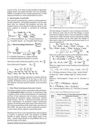
V. SIX PHASE PERMANENT MAGNET
SYNCHRONOUS GENERATOR
Multiphase permanent magnet synchronous generator is
preferred over three-phase generator due to various benefits
such as better efficiency, lower magneto motive force
20th Wind Integration Workshop | Berlin, Germany & Virtually | 29-30 September 2021](https://image.slidesharecdn.com/paper2-220503082613/85/paper_2-pdf-3-320.jpg)
![(MMF) harmonics due to cancellation of air-gap, fault-
tolerant capability, and easy control of multi-machine due to
reduced torque pulsation. On the other hand, there are also
some drawbacks such as cost of permanent magnets,
demagnetization of permanent magnets [20] , and difficulty
in controlling power factor of machine. In this paper, geared
drive train is used because of lower pole number.
Fig. 7 Six-Phase Permanent Magnet Synchronous Generator with Neutral
Isolated
�
𝐔𝐔𝐬𝐬𝐬𝐬𝐬𝐬𝐬𝐬𝐬𝐬𝐬𝐬 = [𝐮𝐮𝐚𝐚 𝐮𝐮𝐛𝐛 𝐮𝐮𝐜𝐜 𝐮𝐮𝐱𝐱 𝐮𝐮𝐲𝐲 𝐮𝐮𝐳𝐳]𝐓𝐓
𝚿𝚿𝐬𝐬𝐬𝐬𝐬𝐬𝐬𝐬𝐬𝐬𝐬𝐬 = [𝚿𝚿𝐚𝐚 𝚿𝚿𝐛𝐛 𝚿𝚿𝐜𝐜 𝚿𝚿𝐱𝐱 𝚿𝚿𝐲𝐲 𝚿𝚿𝐳𝐳]𝐓𝐓
𝐢𝐢𝐬𝐬𝐬𝐬𝐬𝐬𝐬𝐬𝐬𝐬𝐬𝐬 = [𝐢𝐢𝐚𝐚 𝐢𝐢𝐛𝐛 𝐢𝐢𝐜𝐜 𝐢𝐢𝐱𝐱 𝐢𝐢𝐲𝐲 𝐢𝐢𝐳𝐳]𝐓𝐓
(1)
Transformation matrix with shifting angle ∝= 30𝑜𝑜
between
phase abc and xyz of three phase windings.
T =
1
√3
⎣
⎢
⎢
⎢
⎢
⎢
⎡
1
0
1
0
1
√2
0
cos4 ∝
sin 4 ∝
cos8 ∝
sin8 ∝
1
√2
0
cos 8 ∝
sin 8 ∝
cos 4 ∝
sin 4 ∝
1
√2
0
cos ∝
sin ∝
cos ∝
sin ∝
0
1
√2
cos 5 ∝
sin 5 ∝
cos 9 ∝
sin 9 ∝
0
1
√2
cos 9 ∝
sin 9 ∝
cos 5 ∝
sin 5 ∝
0
1
√2 ⎦
⎥
⎥
⎥
⎥
⎥
⎤
The model of the proposed six-phase PMSM is derived based
on the following assumptions:
1) Stator Windings are distributed such that the magneto-
motive force have sinusoidal distribution in the air gap of the
machine and there are no higher order harmonics.
2) Stator winding resistance and inductance at each phase
winding are equal.
3) Hysteresis and eddy current losses are neglected.
4) Mutual leakage inductance is ignored.
5) Machine is considered as non-salient pole machine having
equal direct and quadrature axis inductance i.e. Ld=Lq.
Ideally, voltage level should be consistent so that constant
power is provided when under load. Fig. 8 shows the circuit
diagram of the proposed six phase SGSP propulsion system.
Fig. 8 Circuit diagram of six-phase single generator single propeller
A. Six Phase PMSG Rectifier and Inverter Control
System
Permanent Magnet Synchronous machine can operate both as
a motor and generator. Mechanical power in generator mode
is positive, while in motoring mode considered as negative.
Moreover, PMSM when used as the generator, mechanical
torque is applied to generator shaft through mechanical
coupling between generator and diesel engine. Because of the
application of mechanical torque, current and voltage flow at
the stator coils of a generator as outputs. Conversely, PMSM
when used as motor, current and voltage is applied to motor
stator terminals, and torque is generated as output to propel
the ship. In Fig. 9, PMSG is connected to 2-level 12-pulse
ac-dc converter (rectifier) while PMSM is connected to 2-
level 12-pulse dc-ac converter (inverter).
Fig. 9 Overall Control Diagram of PMSG Connected to AC/DC Converter
Since the control loops are nested, the parameters of the outer
control loop are selected such that the outer voltage control is
slower than the inner current control loop. The overall control
loop is implemented to switch the ac-dc converter by using
sinusoidal pulse width modulation.
∆𝛚𝛚(𝐭𝐭) =
𝟏𝟏
𝟐𝟐𝟐𝟐
∫ (𝐓𝐓𝐦𝐦 − 𝐓𝐓𝐞𝐞) − 𝐊𝐊𝐝𝐝∆𝛚𝛚(𝐭𝐭)𝐝𝐝𝐝𝐝
𝐭𝐭
𝟎𝟎
(2)
Te = Electromagnetic Torque of Machine;
H = Inertia Constant ;
Kd = Damping Factor Representing the Effect of
Damper Winding ; ω(t) = Rotor Mechanical Speed;
∆ω(t) + ω0 = ω(t);
∆ω = Speed Variation with respect to speed of
Operation; Tm = Mechanical Torque of machine
In order to calculate electromagnetic torque of machine,
following equation (3) can be used.
𝐓𝐓𝐞𝐞𝐞𝐞 = 𝐏𝐏 ∗
𝟔𝟔
𝟐𝟐
(𝚿𝚿𝐟𝐟 ∗ 𝐢𝐢𝐪𝐪 + �𝐋𝐋𝐝𝐝 − 𝐋𝐋𝐪𝐪�𝐢𝐢𝐝𝐝𝐢𝐢𝐪𝐪) (3)
Fig. 10 Overall Control Diagram of PMSM Connected to DC/AC Converter
Control structure of PMSM is same in both working
conditions such as generator and motoring mode with
exception that voltage loop is altered with speed control loop
20th Wind Integration Workshop | Berlin, Germany & Virtually | 29-30 September 2021](https://image.slidesharecdn.com/paper2-220503082613/85/paper_2-pdf-4-320.jpg)
![D. Integration of Battery Storage in Onboard DC
System
In case of rapid load variation, it’s quite impossible to run and
stop diesel generator to match fluctuating load demand. This
restriction could be solved by commissioning of on-board
storage device (e.g., Battery Storage Systems) through
which energy could be stored during low load while
delivering stored energy during excessive load demand.
Energy Storage can be a vital addition for vessels that operate
in even the most challenging conditions. In case cruise vessel
enters the port, it can power down its engines since the
batteries onboard function as a backup.
Additionally, battery storage system can have direct
connection to dc-bus or through a dc-dc converter. Although
connection can be done in both ways but it have certain merits
and demerits. Such as, battery doesn’t have consistent output
voltage and fluctuation in battery voltage rely on various
parameters such as battery current, temperature, and SOC
(state-of-charge) [23-24]. In case battery have direct
connection to dc-link, inconsistency in dc-link voltage can
cause higher inrush current, which ultimately curtails the life
span of battery. Variation in dc link voltage causes stability
and protection issue for dc-link, that’s why dc-dc converter is
preferred for interlinking to dc-bus. By using dc-dc converter,
voltages and currents are trackable, which provides
convenience to coordinate ample quantities of battery even-
though state of charge is different [25-30].
E. Interleaved Boost Converter for PV integration
The reason of using interleaved boost converter in designing
of PV power is because it offers several benefits such as
reduced ripple currents in both input and output circuits,
reduced voltage stress across switching device and improved
efficiency and voltage gain. The reason of higher efficiency
is because there is splitting of output currents in two paths,
which ultimately reduces 𝐼𝐼2
𝑅𝑅 losses and inductor AC losses.
On the other hand, circuit diagram consists of four phases
with 𝐿𝐿1 being the filter inductance of first phase, 𝐿𝐿2 being the
inductor of second phase, 𝐿𝐿3 being the inductor of third
phase, and 𝐿𝐿4 being the inductor of fourth phase. IGBT
switches and diodes 𝑆𝑆1, 𝑆𝑆2, 𝑆𝑆3, 𝑆𝑆4 ; and 𝐷𝐷1, 𝐷𝐷2, 𝐷𝐷3, and 𝐷𝐷4 are
the main switches and rectifying diodes of respective phases
as shown in Figure 12.
Fig. 12 Four Phase Fully Interleaved Boost Converter Circuit Diagram
For the analysis of the considered converter following
assumptions are made:
1) 𝐿𝐿1 = 𝐿𝐿2 = 𝐿𝐿3 = 𝐿𝐿4 = 𝐿𝐿 (Where L is the filter inductance
per phase)
2) 𝐶𝐶1 = 𝐶𝐶2 = 𝐶𝐶 (Where C is the filter capacitor)
3) All capacitors and inductors are very large, so that their
ripples are very small.
4) The converter always operates in continuous conduction
mode (CCM). The following Figure. 13 shows the operating
modes of circuit [31].
Fig. 13 Fully Interleaved Boost Converter State-I to State-VIII
The converter is operated at fixed switching frequency𝑓𝑓𝑠𝑠 =
1/𝑇𝑇𝑠𝑠. The operation is such that switches 𝑆𝑆1, 𝑆𝑆2, 𝑆𝑆3 and 𝑆𝑆4 are
turned on and off by respective PWM signals, each phase
shifted from one another by 90-degree with first phase
switched at 0 degree. The converter is analyzed for duty cycle
greater than 0.5 and there are total eight switching states in
one period.
TABLE II. FULLY INTERLEAVED BOOST CONVERTER PARAEMTERS
Table
Head
Design Parameter of Fully Interleaved Boost Converter
Parameters Value Units
1 Power Rating of PV Panel 2*25 kW
2 Parallel Strings of PV 17 -
3
Series Connected Modules Per
String
5 -
4
Inductance of Floating
Interleaved Boost Converter
(𝐿𝐿1 = 𝐿𝐿2 = 𝐿𝐿3 = 𝐿𝐿4)
5 mH
5 DC Link Capacitance (𝐶𝐶𝑑𝑑𝑑𝑑_𝑙𝑙𝑙𝑙𝑙𝑙𝑙𝑙) 4*46000 uF
6 Photo-Voltaic Input Capacitance 5000 uF
7 Converter Switching Frequency 5 kHz
8 DC Bus Voltage (𝑉𝑉𝑑𝑑𝑑𝑑_𝑙𝑙𝑙𝑙𝑙𝑙𝑙𝑙) 1000 Volt
One of the key factor is power management system which is
applicable to all kind of ships. PMS offers more economical
solution by optimization of the vessel’s energy consumption,
optimization of engine loading rate, and reduction of the
maintenance costs. Moreover, its more ecofriendly as
reduction of polluting emissions happens.
20th Wind Integration Workshop | Berlin, Germany & Virtually | 29-30 September 2021](https://image.slidesharecdn.com/paper2-220503082613/85/paper_2-pdf-6-320.jpg)
![VI. CONCLUSION
This paper have comprehensive analysis of control schemes
with thorough consideration of merits and demerits of
proposed topology. Moreover, tremendous rise in energy
demand from generation side is needed to meet the propeller
load profile. The system evaluation is performed on single dc
bus rather than multiple dc bus system, which provide
assistance in regulation of dc-link voltage with enhanced
resilience. For engineers and shipbuilders in particular
container ship pose a tremendous challenge of more power
with a lower fuel consumption. On the other hand, it’s
difficult to maintain balance between power supply and
demand which has been solved by integration of battery
storage, photo-voltaic, and wind energy system.
REFERENCES
[1] E. Skjong, R. Volden, E. Rodskar, M. Molinas, T. A. Johansen, and J.
Cunningham, “Past, present, and future challenges of the marine
vessel’s electrical power system,” IEEE Trans. Transport. Electrific.,
vol. 2, no. 4, pp. 522-537, Dec. 2016.
[2] E. Skjong, E. Rodskar, M. Molinas, T. A. Johansen, and J.
Cunningham, “ The Marine Vessel’s Electrical Power System: From
its Birth to Present Day,” Proc. IEEE, vol. 103, no. 12, pp. 2410-2424,
Dec. 2015.
[3] J. F. Hansen and F. Wendt, “History and state of the art in commercial
electric ship propulsion, integrated power systems, and future trends,”
Proc. IEEE, vol. 103, no. 12, pp. 2229-2242, Dec. 2015.
[4] Kyoto Protocol Reference Manual on Accounting of Emissions and
Assigned Amounts, United Nat. Framework Conv. Climate Change,
New York, NY, USA, 2007.
[5] “Air Pollution.” [Online]. Available:
http://www.imo.org/en/OurWork/Environment/PollutionPrevention/A
irPollution/Pages/Default.aspx. [Accessed: 08-Nov-2019].
[6] T. Yang, T. Cox, M. Degano,S. Bozhko, and C. Gerada, “ History and
Recent Advancements of Electric Propulsion and Integrated Electrical
Power Systems for Commercial & amp; Naval Vessels,” in
International Naval & Maritime Exhibition and Congress for Latin
America, 2016.
[7] Z. Jin, L. Meng, J. C. Vasquez, and J. M. Guerrero, “ Specialized
hierarchical control strategy for DC distribution based shipboard
microgrids: A combination of emerging DC shipboard power systems
and microgrid technologies,” Proc. IECON 2017 -43rd
Annu. Conf.
IEEE Ind. Electron. Soc., vol. 2017-Janua, pp.6820-6825, 2017.
[8] X. Zhaoxia, Z. Tianli, L. Huaimin, J. M. Guerrero, C.-L. Su, and J. C.
Vasquez, “Coordinated Control of a Hybrid-Electric-Ferry Shipboard
Micro-grid,” IEEE Trans. Transp. Electrif., vol. 5, no. 3, pp. 828-839,
2019.
[9] S.-H. Lee, J.-S. Yim, J.-H. Lee, and S.-K. Sul, “Design of Speed
Control Loop of a Variable Speed Diesel Engine Generator By Electric
Governor,” in 2008 IEEE Industry Applications Society Annual
Meeting, 2008, pp. 1-5.
[10] Marqusee, Jeffrey, and Don Janket. “ Reliability of Emergency and
Standby Diesel Generators: Impact on Energy Resilience Solutions.”
2020. Applied Energy, Vol. 268. 15 June 2020. 114918.
[11] R. Geertsma, R. R. Negenborn, K. Visser, and J. J. Hopman, “Design
and control of hybrid power and propulsion systems for smart ships: A
review of developments,” J. Appl. Energy, vol. 194, pp. 30-54, May
2017.
[12] Reference List Miscellaneous Types of Vessels Low Voltage
Propulsion. Accessed: Jun 8, 2017. [Online]. Available:
https://w3.siemens.no/home/no/no/sector/industry/marine/Documents
/Miscellaneous-Types%20of-vessels-references_V2017.pdf
[13] Danfoss: Cruise Skip på Meyer Verft Installerer MER ENN 1000
Danfoss Drives. Accessed: May 10, 2017. [Online]. Available:
http://drives. danfoss.no/newsstories/pe/luxury-cruise-ships-use-
drives/?ref=17179946242#/
[14] Dinesh Kumar, Firuz Zare. “ A Comprehensive Review of Maritime
Microgrids: System Architectures, Energy Efficiency, Power Quality,
and Regulations”, IEEE Access, 2019.
[15] MAERSK: Deepwater Advanced Drill-ships. Accessed: Jun. 15, 2017.
[Online]. Available: https: //www.maerskdrilling.com/en/about-
us/innovation/deepwater-advanced-drillships
[16] Boskalis: Heavy Transport Vessels. Accessed: May 15, 2017. [Online].
Available: https://boskalis.com/about-us/fleet-and-
equipment/offshore-vessels/heavy-transport-vessels.html
[17] Vansail: Container Ship. Accessed: Feb 6, 2017. [Online]. Available:
http: vansail.com/service/sea-freight/
[18] Netwave: The features of Liquefied Natural Gas or LNG Tankers.
Accessed: Feb. 6, 2017. [Online]. Available: https:
//www.netwavesystems.com/features-liquified-natural-gas-lng-
tankers/
[19] H. Lan, S. Wen, Y. Y. Hong, D. C. Yu, and L. Zhang, “Optimal Sizing
of hybrid PV/diesel/battery in ship power system,” Appl. Energy, vol.
158, pp. 26-34, Nov. 2015.
[20] S. Wen, H. Lan, J. Dai, Y.-Y. Hong, D. C. Yu, and L. Yu, “ Economic
Analysis of Hybrid Wind/PV/Diesel/ESS System on a Large Oil
Tanker,” Electr. Power Components Syst., vol. 45, no. 7, pp. 705-714,
Apr. 2017.
[21] F. Niu, B. Wang, A. Babel, K. Li, and E. Strangas, “Comparative
Evaluation of direct torque control strategies for permanent magnet
synchronous machines,” IEEE Transactions on Power Electronics, vol.
31, no. 2, pp. 1408-1424, February 2016.
[22] M. Preindl and S. Bolognani, “Model predictive direct speed control
with finite control set of PMSM drive systems,” IEEE Transactions on
Power Electronics, vol. 28, no. 2, pp. 1007-1015, February 2013.
[23] G. J. Tsekouras and F. D. Kanellos, “ Optimal operation of ship
electrical power system with energy storage systems and Photovoltaics:
Analysis and application,” WSEAS Trans. Power Syst., vol. 8, no. 4,
pp. 145-155, 2013.
[24] M. Mutarraf, Y. Terriche, K. Niazi, J. Vasquez, and J. Guerrero,
“Energy Storage Systems for Shipboard Microgrids – A Review,”
Energies, vol. 11, no. 12, p. 3492, Dec. 2018.
[25] K.-J, Lee, D. Shin, D.-W. Yoo, H.-K, Choi, and H.-J. Kim, “Hybrid
Photovoltaic/diesel green ship operating in stand-alone and grid
connected mode – Experimental Investigation,” Energy, vol. 49, pp.
475-483, Jan. 2013.
[26] M. R. Banaei and R. Alizadeh, “ Simulation-Based Modeling and
Power Management of ALL-Electric Ships Based on Renewable
Energy Generation Using Model Predictive Control Strategy,” IEEE
Intell. Transp. Syst. Mag., vol. 8, no. 2, pp. 90-103, Jun. 2016.
[27] A. A. Alexander, “ Modeling power distribution system of an electric
ship for design and control,” Nanyang Technological University, 2019.
[28] A. Boveri, F. Silvestro, M. Molinas, and E. Skjong, “ Optimal Sizing
of Energy Storage Systems for Shipboard Applications,” IEEE Trans.
Energy Convers., vol. 34, no. 2, pp. 801-811, Jun. 2019.
[29] Z. Jin, L. Meng, J. C. Vasquez, and J. M. Guerrero, “ Specialized
Hierarchical Control Strategy for DC Distribution based shipboard
microgrids: A combination of emerging dc shipboard power systems
and microgrid technologies,” Proc. IECON 2017- 43rd Annu. Conf.
IEEE Ind. Electron. Soc., vol. 2017- Janua, pp. 6820-6825, 2017.
[30] L. Meng et al., “Review on Control of DC Microgrids and Multiple
Microgrid Clusters,” IEEE J. Emerg. Sel. Top. Power Electron., vol. 5,
no. 3, pp. 928-948, Sep. 2017.
[31] D. Kumar, F. Zare, and A. Ghosh, “DC Micro-grid Technology:
System architecture, AC grid interfaces, grounding schemes, power
quality, communication networks, applications, and standardizations
aspects,” IEEE Access, vol. 5, pp. 12230-12256, Jun. 2017.
[32] M. Kabalo, D. Paire, B. Blunier, D. Bouquain, M. G. Simoes, and A.
Miraoui, “ Experimental evaluation of four phase interleaved boost
converter design and control for fuel cell applications,” IET Power
Electron., vol. 6, no. 2, pp. 215-226, 2013.
20th Wind Integration Workshop | Berlin, Germany & Virtually | 29-30 September 2021](https://image.slidesharecdn.com/paper2-220503082613/85/paper_2-pdf-8-320.jpg)


