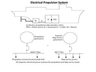
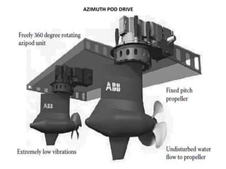
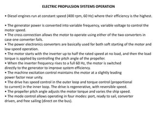
ELECTRIC –PROPULSION
Electric propulsion of ships is dominated by variable-frequency
drive(VFD) technology based on power electronics converters.
The VFD converts the fixed line frequency power to variable-
frequency power at the motor terminals.
The frequency which may vary to match with the required
propeller speed during various phases of ship operations, such as
approaching and leaving a port and while cruising at various
speeds.
Electric propulsion in passenger cruise ships and navy
warships offers minimum noise and vibration and maximum
usable space for paying passengers or for combat weapons.
 It is fully developed in cruise ships, where it has opened up
usable space for passenger cabins to bring greater revenue to
owners.
A common electric propulsion package fitted on many
cruise ships consists of a 21-MW gas turbine driving a 21-MW
generator that powers a synchro converter, cyclo converter, or
pulse width modulated (PWM) VFD with a 20-MW
synchronous motor or an advanced induction motor
For warships, the electric propulsion technology that would
meet military requirements on survivability and stealth is well
under development.
The U.S. Navy is committed to electric propulsion for surface
ships and is investing additional efforts to develop a common
technology that is adaptable to submarines as well.
Electric propulsion technology changes the way a ship transmits
power from the main engine (prime mover) to the propeller and
the way it manages and distributes electrical power to both the
propulsion and non propulsion loads.
It does not change the primary power source of the ship, which
remains the diesel engine, gas turbine, or steam turbine.
Electric propulsion, however, is presently used almost exclusively
in icebreakers and floating offshore oil platforms and is becoming
more common in passenger and car ferries.
Other kinds of commercial ships now being built with electric
propulsion include shuttle tankers, pipe- and cable-laying ships, and
research ships.
Electric propulsion with a podded motor is a norm at present for
cruise ships. The pod propulsion motor is mounted in water beneath
the ship.
 It is used extensively in cruise ships and is being considered for
navy ships as well. Since the pod design is dominated by the motor
and its cooling system, the newly developed compact motor
technology is the main technology enabler for electric propulsion.
Electric propulsion
Most navy ships at present are powered by gas turbines that
drive the propellers by means of heavy reduction gears and
shafts.
In electric propulsion, instead of turning gears, the turbines
directly drive electrical generators at high rpm. The electrical
power is then transmitted by cables toward the stern of the ship
to the motor drive, which modifies the frequency and voltage for
the propulsion motor of the ship to operate at a desired low
speed.
The electric motor then drives the propeller at low rpm. The
ship with multiple propellers has multiple electric motors, motor
drives, and cables, all located inside the hull as shown
A damaged drive shaft can cripple the ship but not so with the
cables, as multiple cables can be used for a desired reliability.
If a missile or torpedo hits the ship, redundant cables can deliver
the propulsion power. The ship service loads are powered by
separate dedicated electrical generators.
MECHANICAL PROPULSION SYSTEM
Electrical Propulsion System
PODDED PROPULSION SYSTEM
The podded propulsion motor is located in water outside the hull
in the same housing that couples it directly to the propeller.
Which eliminates the stern shaft. It gives significant flexibility in
placing the ship components where they offer the greatest benefits
to the overall ship architecture.
Integrated electric propulsion: The propulsion of a ship typically
requires 75–85% of the total power onboard. In electric propulsion,
this power capability is devoted exclusively to ship propulsion and is
not available for non propulsion
use, even when the ship is stationary or travelling at low speed.
The ship with IEP, in contrast, has all engines producing electrical
power at a common bus that is used for both the ship propulsion
and the non propulsion electrical loads as shown in Figure.
Prime movers: The prime movers on commercial ships—particularly those with lower
maximum speeds—are generally diesel engines. On U.S. Navy surface combat ships, they are
gas turbines that burn jet fuel. U.S. Navy submarines the engines are steam turbines
obtaining steam from a nuclear reactor.
Generators: Convert all mechanical power of high-speed engines into electrical
power.
Propulsion power distribution system: Distributes the electrical power to propulsion motors
and other propulsion equipment.
Propulsion motor drives: Modify the frequency and voltage of electrical power as needed
for the electric propulsion motors of the ship to operate at a desired speed during various
operating phases.
Propulsion motors: Convert electrical power from the motor drives to low-rpm mechanical
power suitable for the propellers of the ship.
Propellers: Run at low rpm and propel the ship through water.
Non propulsion power distribution system: Distributes the remaining electrical power to
various non propulsion electrical loads on the ship. This system includes additional motor
drives, cables, and switchgear.
AZIMUTH POD DRIVE
In the azimuth pod drive, the propeller is connected directly to the
motor shaft as shown in Figure .
The fixed-pitch propeller is driven by the variable-speed electric
motor, which is in a submerged pod outside the ship hull, and the pod
can rotate 360° around its vertical axis to give propulsion thrust in any
direction.
Thus, the ship does not need rudders, stern transversal thrusters, or
long shaft lines inside the hull.
The propeller of the pod usually faces forward in the pulling mode.
This reduces the wake and hull resistance and results in higher fuel
economy.
The propeller can be located farther below the stern of the ship in a
clear flow of water, providing greater hydrodynamic and mechanical
efficiencies.
The power rating of the motor fitted in azimuth pod drives
ranges from 5 to 30 MW. The motor type can be 12-pole, 4000-V
synchronous in the higher power range or 640-V induction in the
lower-power range that would run at 150 rpm at 15 Hz.
The stator has either a single or a double winding-type motor as
required for the reliability specification.
 The electrical power is transferred via cables and slip rings in the
slip ring unit. Separate slip rings are provided for the propulsion
motor stator windings, excitation, and control.
The azimuth pod propulsion is used in cruise ships, icebreakers,
navy ships, oil tankers, and offshore rigs.
AZIMUTH POD DRIVE
It eliminates complicated z-drive gears without giving up the
360°maneuverability.
• It gives better maneuvering capabilities with full thrust in all
directions.
• Tugboat need is reduced and completely eliminated on some ships.
• At the stern end, it eliminates the need for a long exposed
horizontal shaft leading to the propeller and rudder for steering the
ship.
• A flexible internal layout saves space in the engine and propulsion
machinery rooms.
• It reduces maintenance and repair since the pod can be detached
and quickly repaired or replaced by a like unit without need for
cutting an opening into the hull of the ship and working around
other equipment.
The pod design thus eliminates many additional systems,
including
(a) rudders and steering gear
(b) propeller shaft and line shaft from the engine
(c) rotating and stationary shaft bulkhead seals
(d) strut and line shaft bearings
(e) Redundant machinery
which saves space by replacing long shaft lines with
electrical cables.
LAY OUT OF ELECTRIC PROPULSION SYSTEM
It starts from the prime movers driving the electrical generators,
which feed power to the main switchboard. The power is then fed
via propulsion transformers to the variable-frequency drives (VFDs)
powering the Azipod motors.
There is an independent control network that supports the
propulsion power distribution network.
 The emerging trends in pod drives is the voltage source pulse
width modulated (PWM) inverter with permanent magnet motor
in lower-power ratings and advance induction motor in higher-
power ratings.
LAY OUT
ELECTRIC PROPULSION ARCHITECTURE
The power system architecture for ships with electric propulsion is
shown inFigure .
It has four 6600-V generators in two groups for redundancy
required for the ABS-R2 class of ships.
In some ships, watertight and fireproof separation is
required between the two groups for ABS-R2S class.
A dedicated emergency generator is not required in this
architecture but may be provided if specifically required.
ELECTRIC PROPULSION ARCHITECTURE
Physical layout of the electrical power system distribution is shown in Figure
ELECTRIC PROPULSION SYSTEMS OPERATION
• Diesel engines run at constant speed (400 rpm, 60 Hz) where their efficiency is the highest.
• The generator power is converted into variable frequency, variable voltage to control the
motor speed.
• The cross connection allows the motor to operate using either of the two converters in
case one converter fails.
• The power electronics converters are basically used for both soft starting of the motor and
low-speed operation.
• The motor starts with the inverter up to half the rated speed at no load, and then the load
torque is applied by controlling the pitch angle of the propeller.
• When the inverter frequency rises to a full 60 Hz, the motor is switched
directly to the generator to improve system efficiency.
• The machine excitation control maintains the motor at a slightly leading
power factor near unity.
• The drive has speed control in the outer loop and torque control (proportional
to current) in the inner loop. The drive is regenerative, with reversible speed.
• The propeller pitch angle adjusts the motor torque and varies the ship speed.
• The mode control allows operating in four modes: port, ready to sail, converter
driven, and free sailing (direct on the bus).
FREQUENCY CONVERTE (CYCLOCONVERTER)
Two main types of frequency converter are
(a) A dc link converter, which first converts ac of one frequency into dc
voltage or current using a rectifier and then inverts dc into another
frequency ac using the voltage source or current source inverter.
(b) A cycloconverter, which converts one frequency ac directly into
another frequency ac by ac-ac conversion. In the past, the cycloconverter
was more economical than the dc link inverter. With decreasing prices of
power semiconductors, it has been gradually replaced by the dc link
converter, which gives lower harmonics in the output.
However, recent advances in fast switching devices and microprocessor
controls are increasing the efficiency and power quality of the
cycloconverter, which may come back in large power applications, such
as in electric propulsion of ships.
THE DC LINK FREQUENCY CONVERTER
Consists of a phase-controlled (α-controlled) three phase rectifier
feeding a dc link with a large filter inductor and a three-phase inverter as shown
in Figure . The large inductor in the dc link works like a constant
current source for the inverter.
The performance of this converter can be analyzed by cascading the
performances of the three-phase rectifier and the three-phase CSI.
The advantage of the dc link converter is a common design that can be
developed for both the induction motor and the synchronous
motor with comparable ratings. For this reason, it is widely used in variable-
frequency drives for ac motors.
The analytical formulation of the instantaneous dc link current is
complex.
However, it can be simplified by the conservation of power relation,
which equates the instantaneous dc power Vdc × Idc with the sum of ac power in
three phases, leading to the following simple relation:
The dc link filter inductor Ldc is designed to smooth out
ripples caused by the source and load side converters
while keeping the ripple current low.
It should have current rating equal to Idc and low
resistance to keep the I2R loss low.
If Iripple(p-p) = permissible ripple current (peak to peak),
Vripple.in and Vripple.out = ripple voltage on the
line and load sides, respectively, and Δt = time increment
between the ripple current peaks, then
NOTE:
After rectification Process : A.C Present in the Out Put D.C --- Ripple
After Inversion Process : D.C Present in the Out Put A.C --- Harmonics
THREE-PHASE CYCLOCONVERTER
The high harmonic content in the single-phase cycloconverter can be
reduced by using the three-phase cycloconverter circuit shown in Figure .
Each output phase consists of a single-phase cycloconverter shown in
Figure .
 The conduction delay angle α in each rectifier and inverter in each
phase is cyclically controlled to yield a low-frequency sinusoidal output
voltage.
Again, due to the harmonic limitations, the maximum output frequency is
limited to about a third of the input line frequency.
For this reason, the three-phase cycloconverter is generally used with
a low-speed, high-power induction motor or synchronous motor typically
used for ship propulsion.
The same thyristor commutating techniques are used in the cycloconverter as
in the ac-dc rectifier.
Some high-power cycloconverters use six thyristors for the positive-wave voltages
and another six thyristors for the negative-wave voltage in each phase, thus using a
total of 36 thyristors for the three-phase design, many more thyristors than the dc
link frequency converter.
The conduction angle cycling scheme controls the ac output voltage, and the firing
frequency controls the output frequency. Both the α-cycling and frequency controls
are complex.
The cycloconverter has been used in the past but was generally out of favour for
many years due to complex controls and many more switching devices, which makes
it more expensive, less reliable, and less efficient.
The new power electronics devices and new cycloconverter designs, however, are
gradually bringing this old technology into a new light.
THYRISTOR TURNOFF (COMMUTATION) CIRCUITS
The thyristor can be turned off (commutated) only by reducing the
current below the holding current IH and applying a reverse-bias voltage for
a certain minimum duration of time called the turnoff time toff.
Then only it recovers the forward blocking characteristic for
continuing operation.
A variety of commutating circuits can be designed for this purpose
as discussed next.
Line Commutation
In the line frequency converter, the thyristor current is
naturally turned off when the
thyristor is reverse biased periodically under a
sinusoidal voltage.
Simple circuit shown in figure the thyristor current
naturally comes to zero every half cycle, when it is
turned off without an additional commutation circuit.
When there are multiple thyristors, as in the full-wave
rectifier, the thyristor current is naturally commutated,
and the device turns off when the next thyristor in the
sequence is fired on.
This is not true in the switch-mode converter (SMC),
in which the thyristor current needs to be forcefully
turned off using an additional commutation circuit.
Forced (Capacitor) Commutation
In the SMC, a forced commutating circuit shown
in figure is needed to turn off
the thyristor.
It uses the capacitor energy to send the counter
current to bring thyristor current to zero.
The positive and negative polarities are those of
the pre charge voltage on the capacitor before
the closure of the auxiliary switch to turn off the
main thyristor.
The inductor controls the di/dt stress on the
switch.
The diode provides the freewheeling path for the
current when needed.
Resonant Commutation
The resonant converter uses
additional inductance Lr and capacitor Cr to
cause the converter circuit to resonate
locally at the switch as shown in .
Such a resonant circuit results in
transient dc current and voltage oscillating
between zero and peak values, and the
switching is done at the natural zero of
current or voltage.
The resonant converter is typically
a full-wave converter that includes inductor
and capacitor as the resonant elements.
Load Commutation
For an inductive load, static or dynamic, as shown in
Figure .
with induction motor load, the thyristors in the inverter
require forced commutation.
However, with a parallel capacitor as shown, a
resonance is created with the load circuit, and the load
current commutation is possible.
The inverter frequency should be slightly above the
resonance frequency, so that the effective load power
factor is leading.
The capacitor should be variable to match with the load
parameters for satisfactory commutation.
This is especially true with the induction motor with
variable-frequency drives, for which the motor frequency
can vary over a wide range, and the leading power factor
can be maintained at all frequencies only with a variable
capacitor.
Presentation on Ship Electric Propulsion.ppt

Presentation on Ship Electric Propulsion.ppt

  • 1.
    ELECTRIC –PROPULSION Electric propulsionof ships is dominated by variable-frequency drive(VFD) technology based on power electronics converters. The VFD converts the fixed line frequency power to variable- frequency power at the motor terminals. The frequency which may vary to match with the required propeller speed during various phases of ship operations, such as approaching and leaving a port and while cruising at various speeds.
  • 2.
    Electric propulsion inpassenger cruise ships and navy warships offers minimum noise and vibration and maximum usable space for paying passengers or for combat weapons.  It is fully developed in cruise ships, where it has opened up usable space for passenger cabins to bring greater revenue to owners. A common electric propulsion package fitted on many cruise ships consists of a 21-MW gas turbine driving a 21-MW generator that powers a synchro converter, cyclo converter, or pulse width modulated (PWM) VFD with a 20-MW synchronous motor or an advanced induction motor
  • 3.
    For warships, theelectric propulsion technology that would meet military requirements on survivability and stealth is well under development. The U.S. Navy is committed to electric propulsion for surface ships and is investing additional efforts to develop a common technology that is adaptable to submarines as well. Electric propulsion technology changes the way a ship transmits power from the main engine (prime mover) to the propeller and the way it manages and distributes electrical power to both the propulsion and non propulsion loads. It does not change the primary power source of the ship, which remains the diesel engine, gas turbine, or steam turbine.
  • 4.
    Electric propulsion, however,is presently used almost exclusively in icebreakers and floating offshore oil platforms and is becoming more common in passenger and car ferries. Other kinds of commercial ships now being built with electric propulsion include shuttle tankers, pipe- and cable-laying ships, and research ships. Electric propulsion with a podded motor is a norm at present for cruise ships. The pod propulsion motor is mounted in water beneath the ship.  It is used extensively in cruise ships and is being considered for navy ships as well. Since the pod design is dominated by the motor and its cooling system, the newly developed compact motor technology is the main technology enabler for electric propulsion.
  • 5.
    Electric propulsion Most navyships at present are powered by gas turbines that drive the propellers by means of heavy reduction gears and shafts. In electric propulsion, instead of turning gears, the turbines directly drive electrical generators at high rpm. The electrical power is then transmitted by cables toward the stern of the ship to the motor drive, which modifies the frequency and voltage for the propulsion motor of the ship to operate at a desired low speed. The electric motor then drives the propeller at low rpm. The ship with multiple propellers has multiple electric motors, motor drives, and cables, all located inside the hull as shown
  • 6.
    A damaged driveshaft can cripple the ship but not so with the cables, as multiple cables can be used for a desired reliability. If a missile or torpedo hits the ship, redundant cables can deliver the propulsion power. The ship service loads are powered by separate dedicated electrical generators.
  • 7.
  • 8.
  • 9.
    PODDED PROPULSION SYSTEM Thepodded propulsion motor is located in water outside the hull in the same housing that couples it directly to the propeller. Which eliminates the stern shaft. It gives significant flexibility in placing the ship components where they offer the greatest benefits to the overall ship architecture. Integrated electric propulsion: The propulsion of a ship typically requires 75–85% of the total power onboard. In electric propulsion, this power capability is devoted exclusively to ship propulsion and is not available for non propulsion use, even when the ship is stationary or travelling at low speed. The ship with IEP, in contrast, has all engines producing electrical power at a common bus that is used for both the ship propulsion and the non propulsion electrical loads as shown in Figure.
  • 11.
    Prime movers: Theprime movers on commercial ships—particularly those with lower maximum speeds—are generally diesel engines. On U.S. Navy surface combat ships, they are gas turbines that burn jet fuel. U.S. Navy submarines the engines are steam turbines obtaining steam from a nuclear reactor. Generators: Convert all mechanical power of high-speed engines into electrical power. Propulsion power distribution system: Distributes the electrical power to propulsion motors and other propulsion equipment. Propulsion motor drives: Modify the frequency and voltage of electrical power as needed for the electric propulsion motors of the ship to operate at a desired speed during various operating phases. Propulsion motors: Convert electrical power from the motor drives to low-rpm mechanical power suitable for the propellers of the ship. Propellers: Run at low rpm and propel the ship through water. Non propulsion power distribution system: Distributes the remaining electrical power to various non propulsion electrical loads on the ship. This system includes additional motor drives, cables, and switchgear.
  • 12.
    AZIMUTH POD DRIVE Inthe azimuth pod drive, the propeller is connected directly to the motor shaft as shown in Figure . The fixed-pitch propeller is driven by the variable-speed electric motor, which is in a submerged pod outside the ship hull, and the pod can rotate 360° around its vertical axis to give propulsion thrust in any direction. Thus, the ship does not need rudders, stern transversal thrusters, or long shaft lines inside the hull. The propeller of the pod usually faces forward in the pulling mode. This reduces the wake and hull resistance and results in higher fuel economy. The propeller can be located farther below the stern of the ship in a clear flow of water, providing greater hydrodynamic and mechanical efficiencies.
  • 13.
    The power ratingof the motor fitted in azimuth pod drives ranges from 5 to 30 MW. The motor type can be 12-pole, 4000-V synchronous in the higher power range or 640-V induction in the lower-power range that would run at 150 rpm at 15 Hz. The stator has either a single or a double winding-type motor as required for the reliability specification.  The electrical power is transferred via cables and slip rings in the slip ring unit. Separate slip rings are provided for the propulsion motor stator windings, excitation, and control. The azimuth pod propulsion is used in cruise ships, icebreakers, navy ships, oil tankers, and offshore rigs.
  • 14.
  • 15.
    It eliminates complicatedz-drive gears without giving up the 360°maneuverability. • It gives better maneuvering capabilities with full thrust in all directions. • Tugboat need is reduced and completely eliminated on some ships. • At the stern end, it eliminates the need for a long exposed horizontal shaft leading to the propeller and rudder for steering the ship. • A flexible internal layout saves space in the engine and propulsion machinery rooms. • It reduces maintenance and repair since the pod can be detached and quickly repaired or replaced by a like unit without need for cutting an opening into the hull of the ship and working around other equipment.
  • 16.
    The pod designthus eliminates many additional systems, including (a) rudders and steering gear (b) propeller shaft and line shaft from the engine (c) rotating and stationary shaft bulkhead seals (d) strut and line shaft bearings (e) Redundant machinery which saves space by replacing long shaft lines with electrical cables.
  • 17.
    LAY OUT OFELECTRIC PROPULSION SYSTEM It starts from the prime movers driving the electrical generators, which feed power to the main switchboard. The power is then fed via propulsion transformers to the variable-frequency drives (VFDs) powering the Azipod motors. There is an independent control network that supports the propulsion power distribution network.  The emerging trends in pod drives is the voltage source pulse width modulated (PWM) inverter with permanent magnet motor in lower-power ratings and advance induction motor in higher- power ratings.
  • 18.
  • 19.
    ELECTRIC PROPULSION ARCHITECTURE Thepower system architecture for ships with electric propulsion is shown inFigure . It has four 6600-V generators in two groups for redundancy required for the ABS-R2 class of ships. In some ships, watertight and fireproof separation is required between the two groups for ABS-R2S class. A dedicated emergency generator is not required in this architecture but may be provided if specifically required.
  • 20.
  • 21.
    Physical layout ofthe electrical power system distribution is shown in Figure
  • 22.
    ELECTRIC PROPULSION SYSTEMSOPERATION • Diesel engines run at constant speed (400 rpm, 60 Hz) where their efficiency is the highest. • The generator power is converted into variable frequency, variable voltage to control the motor speed. • The cross connection allows the motor to operate using either of the two converters in case one converter fails. • The power electronics converters are basically used for both soft starting of the motor and low-speed operation. • The motor starts with the inverter up to half the rated speed at no load, and then the load torque is applied by controlling the pitch angle of the propeller. • When the inverter frequency rises to a full 60 Hz, the motor is switched directly to the generator to improve system efficiency. • The machine excitation control maintains the motor at a slightly leading power factor near unity. • The drive has speed control in the outer loop and torque control (proportional to current) in the inner loop. The drive is regenerative, with reversible speed. • The propeller pitch angle adjusts the motor torque and varies the ship speed. • The mode control allows operating in four modes: port, ready to sail, converter driven, and free sailing (direct on the bus).
  • 24.
    FREQUENCY CONVERTE (CYCLOCONVERTER) Twomain types of frequency converter are (a) A dc link converter, which first converts ac of one frequency into dc voltage or current using a rectifier and then inverts dc into another frequency ac using the voltage source or current source inverter. (b) A cycloconverter, which converts one frequency ac directly into another frequency ac by ac-ac conversion. In the past, the cycloconverter was more economical than the dc link inverter. With decreasing prices of power semiconductors, it has been gradually replaced by the dc link converter, which gives lower harmonics in the output. However, recent advances in fast switching devices and microprocessor controls are increasing the efficiency and power quality of the cycloconverter, which may come back in large power applications, such as in electric propulsion of ships.
  • 25.
    THE DC LINKFREQUENCY CONVERTER Consists of a phase-controlled (α-controlled) three phase rectifier feeding a dc link with a large filter inductor and a three-phase inverter as shown in Figure . The large inductor in the dc link works like a constant current source for the inverter. The performance of this converter can be analyzed by cascading the performances of the three-phase rectifier and the three-phase CSI. The advantage of the dc link converter is a common design that can be developed for both the induction motor and the synchronous motor with comparable ratings. For this reason, it is widely used in variable- frequency drives for ac motors. The analytical formulation of the instantaneous dc link current is complex. However, it can be simplified by the conservation of power relation, which equates the instantaneous dc power Vdc × Idc with the sum of ac power in three phases, leading to the following simple relation:
  • 27.
    The dc linkfilter inductor Ldc is designed to smooth out ripples caused by the source and load side converters while keeping the ripple current low. It should have current rating equal to Idc and low resistance to keep the I2R loss low. If Iripple(p-p) = permissible ripple current (peak to peak), Vripple.in and Vripple.out = ripple voltage on the line and load sides, respectively, and Δt = time increment between the ripple current peaks, then NOTE: After rectification Process : A.C Present in the Out Put D.C --- Ripple After Inversion Process : D.C Present in the Out Put A.C --- Harmonics
  • 28.
    THREE-PHASE CYCLOCONVERTER The highharmonic content in the single-phase cycloconverter can be reduced by using the three-phase cycloconverter circuit shown in Figure . Each output phase consists of a single-phase cycloconverter shown in Figure .  The conduction delay angle α in each rectifier and inverter in each phase is cyclically controlled to yield a low-frequency sinusoidal output voltage. Again, due to the harmonic limitations, the maximum output frequency is limited to about a third of the input line frequency. For this reason, the three-phase cycloconverter is generally used with a low-speed, high-power induction motor or synchronous motor typically used for ship propulsion.
  • 29.
    The same thyristorcommutating techniques are used in the cycloconverter as in the ac-dc rectifier. Some high-power cycloconverters use six thyristors for the positive-wave voltages and another six thyristors for the negative-wave voltage in each phase, thus using a total of 36 thyristors for the three-phase design, many more thyristors than the dc link frequency converter. The conduction angle cycling scheme controls the ac output voltage, and the firing frequency controls the output frequency. Both the α-cycling and frequency controls are complex. The cycloconverter has been used in the past but was generally out of favour for many years due to complex controls and many more switching devices, which makes it more expensive, less reliable, and less efficient. The new power electronics devices and new cycloconverter designs, however, are gradually bringing this old technology into a new light.
  • 31.
    THYRISTOR TURNOFF (COMMUTATION)CIRCUITS The thyristor can be turned off (commutated) only by reducing the current below the holding current IH and applying a reverse-bias voltage for a certain minimum duration of time called the turnoff time toff. Then only it recovers the forward blocking characteristic for continuing operation. A variety of commutating circuits can be designed for this purpose as discussed next.
  • 32.
    Line Commutation In theline frequency converter, the thyristor current is naturally turned off when the thyristor is reverse biased periodically under a sinusoidal voltage. Simple circuit shown in figure the thyristor current naturally comes to zero every half cycle, when it is turned off without an additional commutation circuit. When there are multiple thyristors, as in the full-wave rectifier, the thyristor current is naturally commutated, and the device turns off when the next thyristor in the sequence is fired on. This is not true in the switch-mode converter (SMC), in which the thyristor current needs to be forcefully turned off using an additional commutation circuit.
  • 33.
    Forced (Capacitor) Commutation Inthe SMC, a forced commutating circuit shown in figure is needed to turn off the thyristor. It uses the capacitor energy to send the counter current to bring thyristor current to zero. The positive and negative polarities are those of the pre charge voltage on the capacitor before the closure of the auxiliary switch to turn off the main thyristor. The inductor controls the di/dt stress on the switch. The diode provides the freewheeling path for the current when needed.
  • 34.
    Resonant Commutation The resonantconverter uses additional inductance Lr and capacitor Cr to cause the converter circuit to resonate locally at the switch as shown in . Such a resonant circuit results in transient dc current and voltage oscillating between zero and peak values, and the switching is done at the natural zero of current or voltage. The resonant converter is typically a full-wave converter that includes inductor and capacitor as the resonant elements.
  • 35.
    Load Commutation For aninductive load, static or dynamic, as shown in Figure . with induction motor load, the thyristors in the inverter require forced commutation. However, with a parallel capacitor as shown, a resonance is created with the load circuit, and the load current commutation is possible. The inverter frequency should be slightly above the resonance frequency, so that the effective load power factor is leading. The capacitor should be variable to match with the load parameters for satisfactory commutation. This is especially true with the induction motor with variable-frequency drives, for which the motor frequency can vary over a wide range, and the leading power factor can be maintained at all frequencies only with a variable capacitor.

Editor's Notes