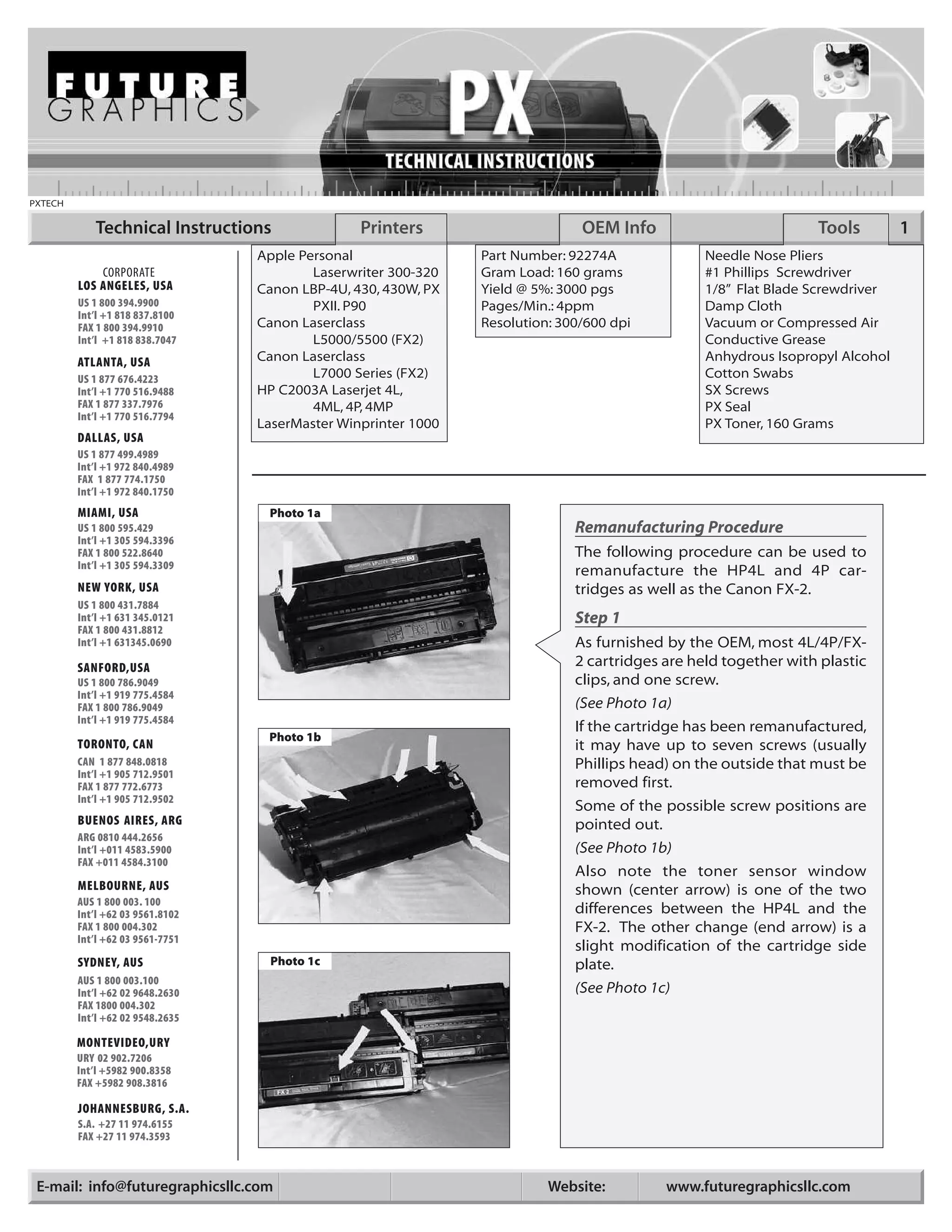
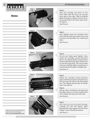
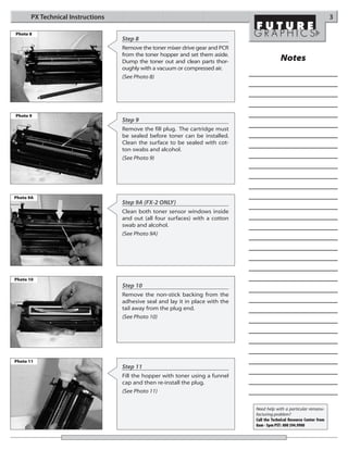
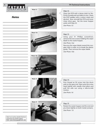
PXTECH

            Technical Instructions               Printers                      OEM Info                          Tools         1
                                  Apple Personal                Part Number: 92274A              Needle Nose Pliers
             CORPORATE                    Laserwriter 300-320   Gram Load: 160 grams             #1 Phillips Screwdriver
         LOS ANGELES, USA         Canon LBP-4U, 430, 430W, PX   Yield @ 5%: 3000 pgs             1/8” Flat Blade Screwdriver
         US 1 800 394.9900                PXII. P90             Pages/Min.: 4ppm                 Damp Cloth
         Int’l +1 818 837.8100
         FAX 1 800 394.9910       Canon Laserclass              Resolution: 300/600 dpi          Vacuum or Compressed Air
         Int’l +1 818 838.7047            L5000/5500 (FX2)                                       Conductive Grease
         ATLANTA, USA             Canon Laserclass                                               Anhydrous Isopropyl Alcohol
         US 1 877 676.4223                L7000 Series (FX2)                                     Cotton Swabs
         Int’l +1 770 516.9488    HP C2003A Laserjet 4L,                                         SX Screws
         FAX 1 877 337.7976               4ML, 4P, 4MP                                           PX Seal
         Int’l +1 770 516.7794
                                  LaserMaster Winprinter 1000                                    PX Toner, 160 Grams
         DALLAS, USA
         US 1 877 499.4989
         Int’l +1 972 840.4989
         FAX 1 877 774.1750
         Int’l +1 972 840.1750
         MIAMI, USA                Photo 1a
         US 1 800 595.429                                                     Remanufacturing Procedure
         Int’l +1 305 594.3396
         FAX 1 800 522.8640                                                   The following procedure can be used to
         Int’l +1 305 594.3309
                                                                              remanufacture the HP4L and 4P car-
         NEW YORK, USA                                                        tridges as well as the Canon FX-2.
         US 1 800 431.7884
         Int’l +1 631 345.0121                                                Step 1
         FAX 1 800 431.8812
         Int’l +1 631345.0690                                                 As furnished by the OEM, most 4L/4P/FX-
         SANFORD,USA                                                          2 cartridges are held together with plastic
         US 1 800 786.9049                                                    clips, and one screw.
         Int’l +1 919 775.4584
         FAX 1 800 786.9049                                                   (See Photo 1a)
         Int’l +1 919 775.4584
                                                                              If the cartridge has been remanufactured,
                                   Photo 1b
         TORONTO, CAN                                                         it may have up to seven screws (usually
         CAN 1 877 848.0818                                                   Phillips head) on the outside that must be
         Int’l +1 905 712.9501
         FAX 1 877 772.6773                                                   removed first.
         Int’l +1 905 712.9502
                                                                              Some of the possible screw positions are
         BUENOS AIRES, ARG                                                    pointed out.
         ARG 0810 444.2656
         Int’l +011 4583.5900                                                 (See Photo 1b)
         FAX +011 4584.3100
                                                                              Also note the toner sensor window
         MELBOURNE, AUS                                                       shown (center arrow) is one of the two
         AUS 1 800 003. 100
         Int’l +62 03 9561.8102                                               differences between the HP4L and the
         FAX 1 800 004.302                                                    FX-2. The other change (end arrow) is a
         Int’l +62 03 9561-7751
                                                                              slight modification of the cartridge side
         SYDNEY, AUS               Photo 1c                                   plate.
         AUS 1 800 003.100
         Int’l +62 02 9648.2630                                               (See Photo 1c)
         FAX 1800 004.302
         Int’l +62 02 9548.2635

         MONTEVIDEO,URY
         URY 02 902.7206
         Int’l +5982 900.8358
         FAX +5982 908.3816

         JOHANNESBURG, S.A.
         S.A. +27 11 974.6155
         FAX +27 11 974.3593


 E-mail: info@futuregraphicsllc.com                                       Website:         www.futuregraphicsllc.com
2                                                              PX Technical Instructions

                                            Photo 2
                                                      Step 2
                                                      Place the cartridge, top down, on the
                                                      work table with the drum up and the
              Notes                                   drum gear to the right. With a small flat
                                                      blade screwdriver release the first clip in
                                                      the square hole in the lower right corner
                                                      facing you.
                                                      (See Photo 2)


                                            Photo 3
                                                      Step 3
                                                      Next, slightly rotate the cartridge clock-
                                                      wise with the drum gear closer to you and
                                                      pry loose the clip below the metal drum
                                                      shaft.
                                                      (See Photo 3)


                                            Photo 4
                                                      Step 4
                                                      Pry the two halves apart slightly. Now,
                                                      rotate the cartridge counter-clockwise
                                                      back to its original position and pry loose
                                                      the four clips facing you (start with the one
                                                      on the drum gear end). This can be done
                                                      with two small flat blade screwdrivers to
                                                      avoid breaking the plastic cartridge clips.
                                                      (See Photo 4)


                                            Photo 6
                                                      Step 5
                                                      Rotate the cartridge counter-clockwise
                                                      again until the drum gear is away from you
                                                      and pry loose the clip on the end toward
                                                      you. This releases the last clip. Be careful,
                                                      toner may spill out.
                                                      Step 6
                                                      Pull the drum coverall the way back and
                                                      then flip it down so it tucks in behind the
                                                      toner hopper and stays out of the way.
                                            Photo 7   (See Photo 6)


                                                      Step 7
                                                      Now, work your way around the cartridge,
                                                      carefully pry the two halves apart.
                                                      Separate the waste hopper from the toner
    Need trust-worthy, detailed Technical             hopper. Toner will spill everywhere.
    Instructions for another engine?
                                                      (See Photo 7)
    Visit: www.futuregraphicsllc.com
PX Technical Instructions                                                                                          3

Photo 8
                                   Step 8
                                   Remove the toner mixer drive gear and PCR
                                   from the toner hopper and set them aside.
                                   Dump the toner out and clean parts thor-                  Notes
                                   oughly with a vacuum or compressed air.
                                   (See Photo 8)


Photo 9
                                   Step 9
                                   Remove the fill plug. The cartridge must
                                   be sealed before toner can be installed.
                                   Clean the surface to be sealed with cot-
                                   ton swabs and alcohol.
                                   (See Photo 9)


Photo 9A
                                   Step 9A (FX-2 ONLY)
                                   Clean both toner sensor windows inside
                                   and out (all four surfaces) with a cotton
                                   swab and alcohol.
                                   (See Photo 9A)


Photo 10
                                   Step 10
                                   Remove the non-stick backing from the
                                   adhesive seal and lay it in place with the
                                   tail away from the plug end.
                                   (See Photo 10)


Photo 11
                                   Step 11
                                   Fill the hopper with toner using a funnel
                                   cap and then re-install the plug.
                                   (See Photo 11)


                                                                                Need help with a particular remanu-
                                                                                facturing problem?
                                                                                Call the Technical Resource Center from
                                                                                8am - 5pm PST: 800 394.9900
4                                                                 PX Technical Instructions

                                            Photo 12
                                                        Step 12
                                                        Clean the PCR with a damp cloth (or Nu-
                                                        Finish if preferred) and allow to dry. Clean
              Notes                                     the PCR saddles with a cotton swab and
                                                        alcohol. Now reinstall the PCR and toner
                                                        mixer drive gear. Set the toner hopper
                                                        aside until Step 25.
                                                        (See Photo 12)


                                            Photo 13a
                                                        Step 13
                                                        Using your #1 Phillips screwdriver,
                                                        remove the two screws holding the wiper
                                                        blade to the waste hopper.
                                                        (See Photo 13a)
                                                        Now pry the wiper blade toward the non-
                                                        gear side in order no to break the plastic
                                                        guide. Then remove the wiper blade.
                                                        (See Photo 13b)

                                            Photo 13b


                                            Photo 14
                                                        Step 14
                                                        First, thread an SX screw into the drum
                                                        axle on the gear end. Next, grip the screw
                                                        head tightly with needle nose pliers and
                                                        pull the axle out using a side-to-side
                                                        motion.
                                                        (See Photo 14)


                                            Photo 15
                                                        Step 15
                                                        Rotate the waste hopper end-for-end and
                                                        pry down lightly on both metal contacts.
                                                        (See Photo 15)


    Need trust-worthy, detailed Technical
    Instructions for another engine?
    Visit: www.futuregraphicsllc.com
PX Technical Instructions                                                                                           5

Photo 16
                                   Step 16
                                   Pry off the large white side plate. Locate
                                   the metal mag roller contact plate and
                                   drum ground contact arms. Clean off the
                                                                                              Notes
                                   old conductive grease from these sur-
                                   faces and replace it with new conductive
                                   grease, or leave the parts dry.
                                   (See Photo 16)


Photo 17
                                   Step 17
                                   Remove the drum, wrap it in protective
                                   cloth or paper, and set it aside until Step
                                   22.
                                   (See Photo 17)


Photo 18
                                   Step 18
                                   Push down and forward on the white
                                   mag roller guide plate latch. Push the
                                   mag roller forward and lift out. Clean with
                                   isopropyl alcohol or commercial mag
                                   roller cleaner. Clean mag roller contacts
                                   with a cotton swab and alcohol. Clean
                                   the doctor blade lightly with isopropyl
                                   alcohol.(See Photo 18)


Photo 19
                                   Step 19
                                   Re-install the mag roller assembly-gear
                                   end first- with the spring of the guide
                                   plate facing toward the slot. Snap it into
                                   position.
                                   (See Photo 19)


Photo 20
                                   Step 20
                                   Clean the drum with isopropyl alcohol,
                                   allow to dry, and cover lightly with
                                   padding powder. Press the drum down
                                   into position with the drum and mag
                                   roller gears meshed.
                                   (See Photo 20)                                Need help with a particular remanu-
                                                                                 facturing problem?
                                                                                 Call the Technical Resource Center from
                                                                                 8am - 5pm PST: 800 394.9900
6                                                                                                                                          PX Technical Instructions

                                                               Photo 21
                                                                                                                                  Step 21
                                                                                                                                  Re-install the large white side plate with
                  Notes                                                                                                           its metal drum ground contacts and mag
                                                                                                                                  roller bias contact, aligning the flat side of
                                                                                                                                  the magnet shaft with the flat portion of
                                                                                                                                  the side plate opening. Reposition and
                                                                                                                                  snap both metal contact points into
                                                                                                                                  place.
                                                                                                                                  (See Photo 25b)


                                                                 Step 22
                                                                 Re-install drum axle on the drum gear side by pressing it flush with your thumb.
                                                                 Step 23
                                                                 Slide the wiper blade down into position and re-install the two Phillips screws. Turn
                                                                 the drum 360 degrees to remove excess padding powder.


                                                               Photo 22
                                                                                                                                  Step 24
                                                                                                                                  Return to the toner hopper, make sure the
                                                                                                                                  tail end of the seal is tucked through the
                                                                                                                                  access slot, pull it too the rear with your
                                                                                                                                  right hand.
                                                                                                                                  (See Photo 24)


                                                               Photo 23
                                                                                                                                  Step 25
                                                                                                                                  Align the two halves (toner hopper and
                                                                                                                                  waste hopper) and press them together
                                                                                                                                  until all eleven clips snap into place..
                                                                                                                                  (See Photo 25)
                                                                                                                                  Install one screw in the top left corner of
                                                                                                                                  the cartridge, as shown at the arrow on
                                                                                                                                  the first photo in this guide.
                                                                                                                                  NOTE: If you have broken off any clips or
                                                                                                                                  are worried about leakage, you may use
                                                                                                                                  up to seven SX screws to hold the two
                                                                                                                                  halves together.


                                                                                                                                  Step 26
                                                                                                                                  Unfold and return the drum cover (shut-
                                                                                                                                  ter) back to its original position.
                                                                                                                                  NOTE: Both the HP4L and the FX-2 can be
                                                                                                                                  tested in a 4L or 4P printer, but the HP4L
                                                                                                                                  will not fit into an FX-2 fax machine.
Future Graphics (FG) is a distributor of compatible replacement parts and products for imagining equipment. None of FG's
products are genuine OEM replacement parts and no affiliation or sponsorship is to be implied between FG and any OEM.


E-mail: info@futuregraphicsllc.com                                                                                     Website:          www.futuregraphicsllc.com

Manual de Recarga HP Canon PX 92274A.

  • 1.
    PXTECH Technical Instructions Printers OEM Info Tools 1 Apple Personal Part Number: 92274A Needle Nose Pliers CORPORATE Laserwriter 300-320 Gram Load: 160 grams #1 Phillips Screwdriver LOS ANGELES, USA Canon LBP-4U, 430, 430W, PX Yield @ 5%: 3000 pgs 1/8” Flat Blade Screwdriver US 1 800 394.9900 PXII. P90 Pages/Min.: 4ppm Damp Cloth Int’l +1 818 837.8100 FAX 1 800 394.9910 Canon Laserclass Resolution: 300/600 dpi Vacuum or Compressed Air Int’l +1 818 838.7047 L5000/5500 (FX2) Conductive Grease ATLANTA, USA Canon Laserclass Anhydrous Isopropyl Alcohol US 1 877 676.4223 L7000 Series (FX2) Cotton Swabs Int’l +1 770 516.9488 HP C2003A Laserjet 4L, SX Screws FAX 1 877 337.7976 4ML, 4P, 4MP PX Seal Int’l +1 770 516.7794 LaserMaster Winprinter 1000 PX Toner, 160 Grams DALLAS, USA US 1 877 499.4989 Int’l +1 972 840.4989 FAX 1 877 774.1750 Int’l +1 972 840.1750 MIAMI, USA Photo 1a US 1 800 595.429 Remanufacturing Procedure Int’l +1 305 594.3396 FAX 1 800 522.8640 The following procedure can be used to Int’l +1 305 594.3309 remanufacture the HP4L and 4P car- NEW YORK, USA tridges as well as the Canon FX-2. US 1 800 431.7884 Int’l +1 631 345.0121 Step 1 FAX 1 800 431.8812 Int’l +1 631345.0690 As furnished by the OEM, most 4L/4P/FX- SANFORD,USA 2 cartridges are held together with plastic US 1 800 786.9049 clips, and one screw. Int’l +1 919 775.4584 FAX 1 800 786.9049 (See Photo 1a) Int’l +1 919 775.4584 If the cartridge has been remanufactured, Photo 1b TORONTO, CAN it may have up to seven screws (usually CAN 1 877 848.0818 Phillips head) on the outside that must be Int’l +1 905 712.9501 FAX 1 877 772.6773 removed first. Int’l +1 905 712.9502 Some of the possible screw positions are BUENOS AIRES, ARG pointed out. ARG 0810 444.2656 Int’l +011 4583.5900 (See Photo 1b) FAX +011 4584.3100 Also note the toner sensor window MELBOURNE, AUS shown (center arrow) is one of the two AUS 1 800 003. 100 Int’l +62 03 9561.8102 differences between the HP4L and the FAX 1 800 004.302 FX-2. The other change (end arrow) is a Int’l +62 03 9561-7751 slight modification of the cartridge side SYDNEY, AUS Photo 1c plate. AUS 1 800 003.100 Int’l +62 02 9648.2630 (See Photo 1c) FAX 1800 004.302 Int’l +62 02 9548.2635 MONTEVIDEO,URY URY 02 902.7206 Int’l +5982 900.8358 FAX +5982 908.3816 JOHANNESBURG, S.A. S.A. +27 11 974.6155 FAX +27 11 974.3593 E-mail: info@futuregraphicsllc.com Website: www.futuregraphicsllc.com
  • 2.
    2 PX Technical Instructions Photo 2 Step 2 Place the cartridge, top down, on the work table with the drum up and the Notes drum gear to the right. With a small flat blade screwdriver release the first clip in the square hole in the lower right corner facing you. (See Photo 2) Photo 3 Step 3 Next, slightly rotate the cartridge clock- wise with the drum gear closer to you and pry loose the clip below the metal drum shaft. (See Photo 3) Photo 4 Step 4 Pry the two halves apart slightly. Now, rotate the cartridge counter-clockwise back to its original position and pry loose the four clips facing you (start with the one on the drum gear end). This can be done with two small flat blade screwdrivers to avoid breaking the plastic cartridge clips. (See Photo 4) Photo 6 Step 5 Rotate the cartridge counter-clockwise again until the drum gear is away from you and pry loose the clip on the end toward you. This releases the last clip. Be careful, toner may spill out. Step 6 Pull the drum coverall the way back and then flip it down so it tucks in behind the toner hopper and stays out of the way. Photo 7 (See Photo 6) Step 7 Now, work your way around the cartridge, carefully pry the two halves apart. Separate the waste hopper from the toner Need trust-worthy, detailed Technical hopper. Toner will spill everywhere. Instructions for another engine? (See Photo 7) Visit: www.futuregraphicsllc.com
  • 3.
    PX Technical Instructions 3 Photo 8 Step 8 Remove the toner mixer drive gear and PCR from the toner hopper and set them aside. Dump the toner out and clean parts thor- Notes oughly with a vacuum or compressed air. (See Photo 8) Photo 9 Step 9 Remove the fill plug. The cartridge must be sealed before toner can be installed. Clean the surface to be sealed with cot- ton swabs and alcohol. (See Photo 9) Photo 9A Step 9A (FX-2 ONLY) Clean both toner sensor windows inside and out (all four surfaces) with a cotton swab and alcohol. (See Photo 9A) Photo 10 Step 10 Remove the non-stick backing from the adhesive seal and lay it in place with the tail away from the plug end. (See Photo 10) Photo 11 Step 11 Fill the hopper with toner using a funnel cap and then re-install the plug. (See Photo 11) Need help with a particular remanu- facturing problem? Call the Technical Resource Center from 8am - 5pm PST: 800 394.9900
  • 4.
    4 PX Technical Instructions Photo 12 Step 12 Clean the PCR with a damp cloth (or Nu- Finish if preferred) and allow to dry. Clean Notes the PCR saddles with a cotton swab and alcohol. Now reinstall the PCR and toner mixer drive gear. Set the toner hopper aside until Step 25. (See Photo 12) Photo 13a Step 13 Using your #1 Phillips screwdriver, remove the two screws holding the wiper blade to the waste hopper. (See Photo 13a) Now pry the wiper blade toward the non- gear side in order no to break the plastic guide. Then remove the wiper blade. (See Photo 13b) Photo 13b Photo 14 Step 14 First, thread an SX screw into the drum axle on the gear end. Next, grip the screw head tightly with needle nose pliers and pull the axle out using a side-to-side motion. (See Photo 14) Photo 15 Step 15 Rotate the waste hopper end-for-end and pry down lightly on both metal contacts. (See Photo 15) Need trust-worthy, detailed Technical Instructions for another engine? Visit: www.futuregraphicsllc.com
  • 5.
    PX Technical Instructions 5 Photo 16 Step 16 Pry off the large white side plate. Locate the metal mag roller contact plate and drum ground contact arms. Clean off the Notes old conductive grease from these sur- faces and replace it with new conductive grease, or leave the parts dry. (See Photo 16) Photo 17 Step 17 Remove the drum, wrap it in protective cloth or paper, and set it aside until Step 22. (See Photo 17) Photo 18 Step 18 Push down and forward on the white mag roller guide plate latch. Push the mag roller forward and lift out. Clean with isopropyl alcohol or commercial mag roller cleaner. Clean mag roller contacts with a cotton swab and alcohol. Clean the doctor blade lightly with isopropyl alcohol.(See Photo 18) Photo 19 Step 19 Re-install the mag roller assembly-gear end first- with the spring of the guide plate facing toward the slot. Snap it into position. (See Photo 19) Photo 20 Step 20 Clean the drum with isopropyl alcohol, allow to dry, and cover lightly with padding powder. Press the drum down into position with the drum and mag roller gears meshed. (See Photo 20) Need help with a particular remanu- facturing problem? Call the Technical Resource Center from 8am - 5pm PST: 800 394.9900
  • 6.
    6 PX Technical Instructions Photo 21 Step 21 Re-install the large white side plate with Notes its metal drum ground contacts and mag roller bias contact, aligning the flat side of the magnet shaft with the flat portion of the side plate opening. Reposition and snap both metal contact points into place. (See Photo 25b) Step 22 Re-install drum axle on the drum gear side by pressing it flush with your thumb. Step 23 Slide the wiper blade down into position and re-install the two Phillips screws. Turn the drum 360 degrees to remove excess padding powder. Photo 22 Step 24 Return to the toner hopper, make sure the tail end of the seal is tucked through the access slot, pull it too the rear with your right hand. (See Photo 24) Photo 23 Step 25 Align the two halves (toner hopper and waste hopper) and press them together until all eleven clips snap into place.. (See Photo 25) Install one screw in the top left corner of the cartridge, as shown at the arrow on the first photo in this guide. NOTE: If you have broken off any clips or are worried about leakage, you may use up to seven SX screws to hold the two halves together. Step 26 Unfold and return the drum cover (shut- ter) back to its original position. NOTE: Both the HP4L and the FX-2 can be tested in a 4L or 4P printer, but the HP4L will not fit into an FX-2 fax machine. Future Graphics (FG) is a distributor of compatible replacement parts and products for imagining equipment. None of FG's products are genuine OEM replacement parts and no affiliation or sponsorship is to be implied between FG and any OEM. E-mail: info@futuregraphicsllc.com Website: www.futuregraphicsllc.com