Downloaded 261 times
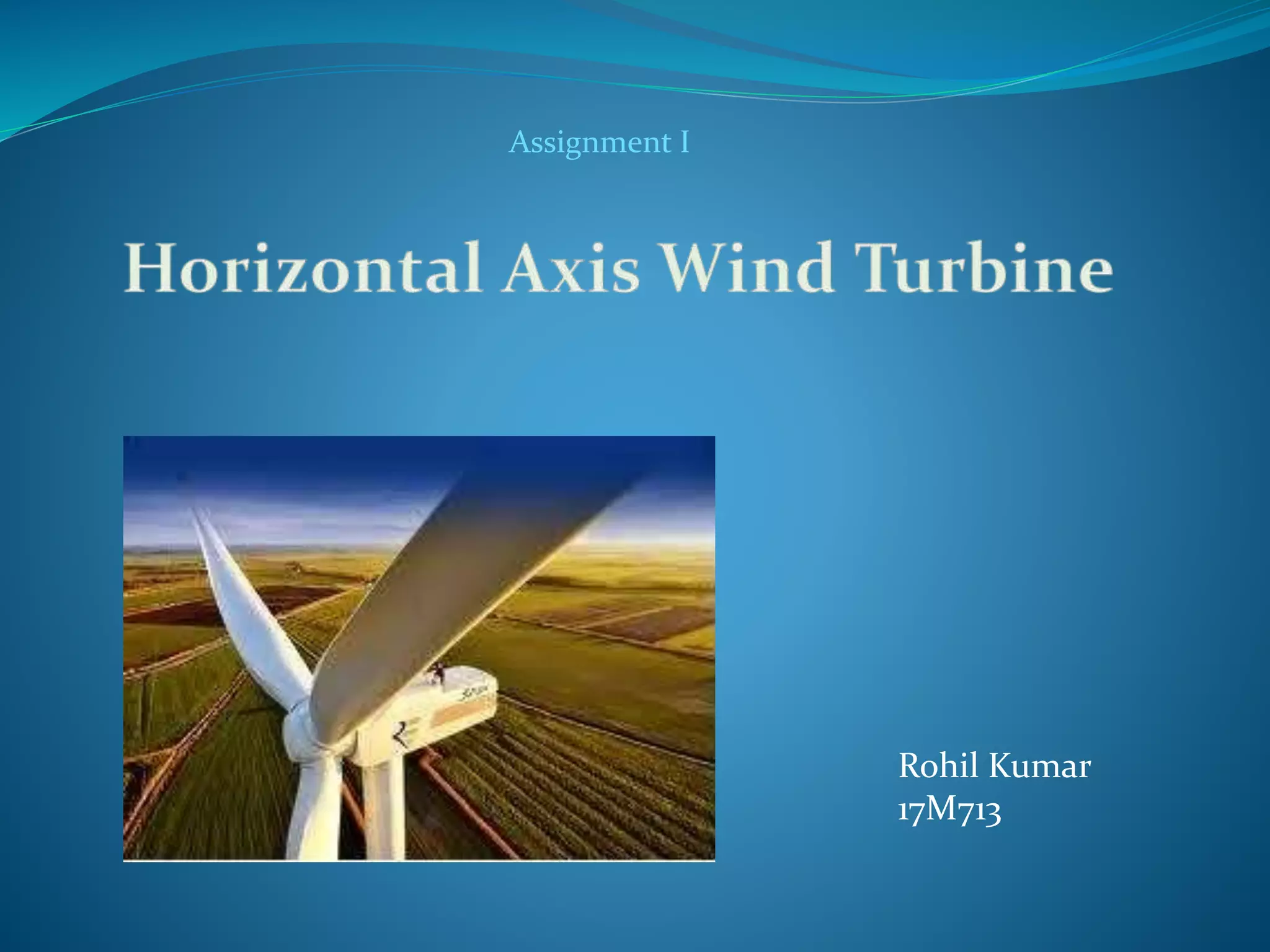
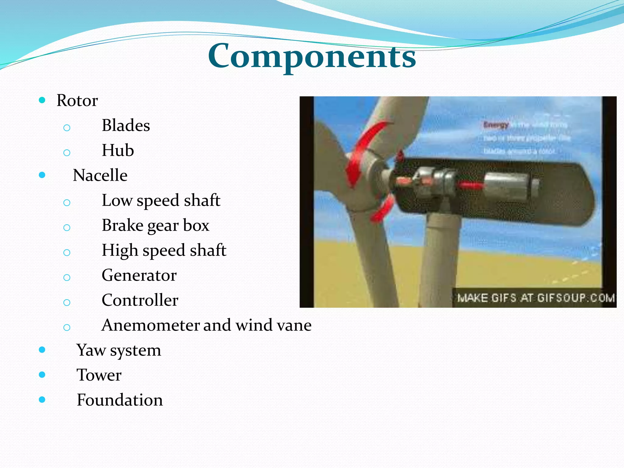
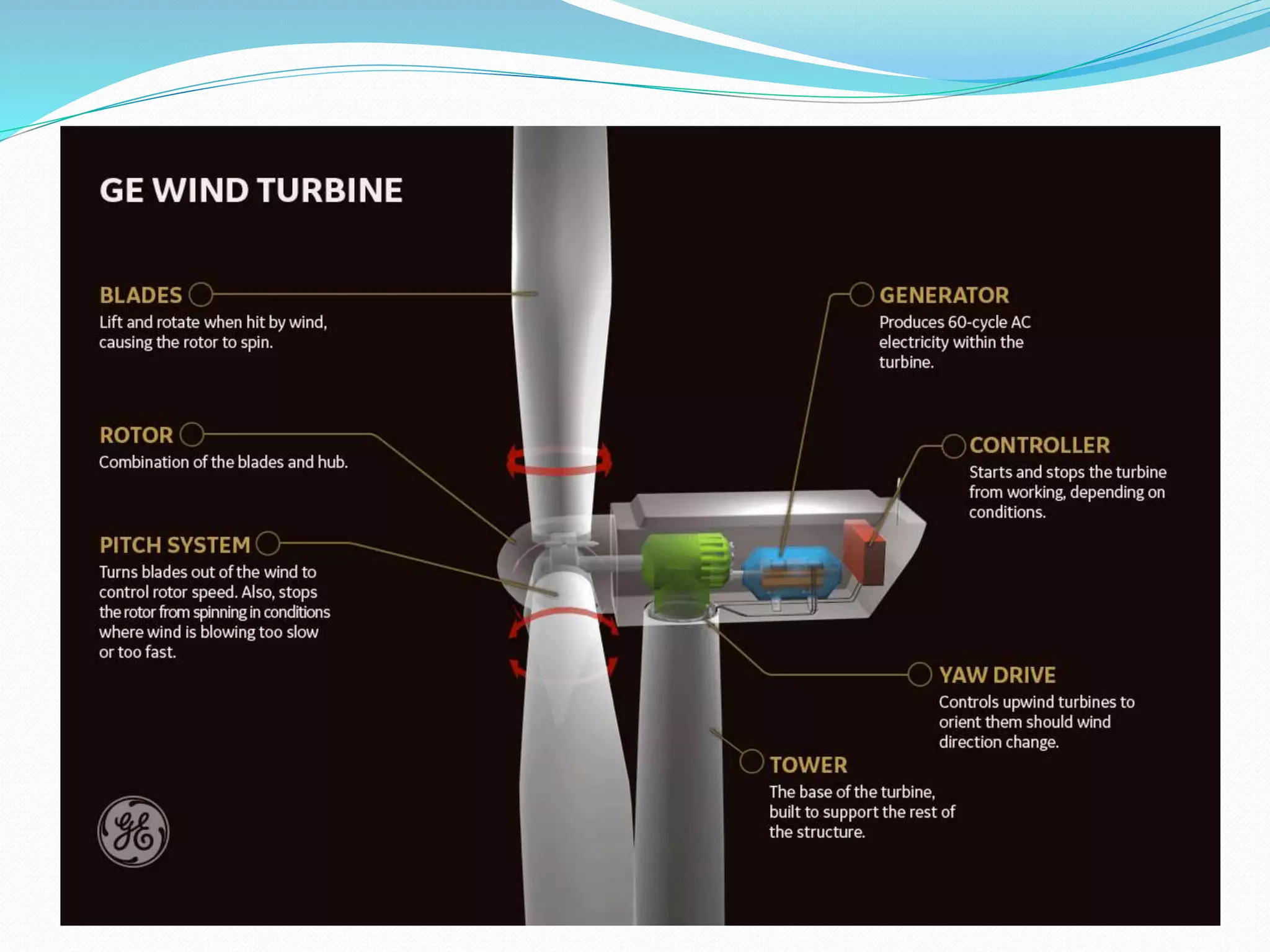
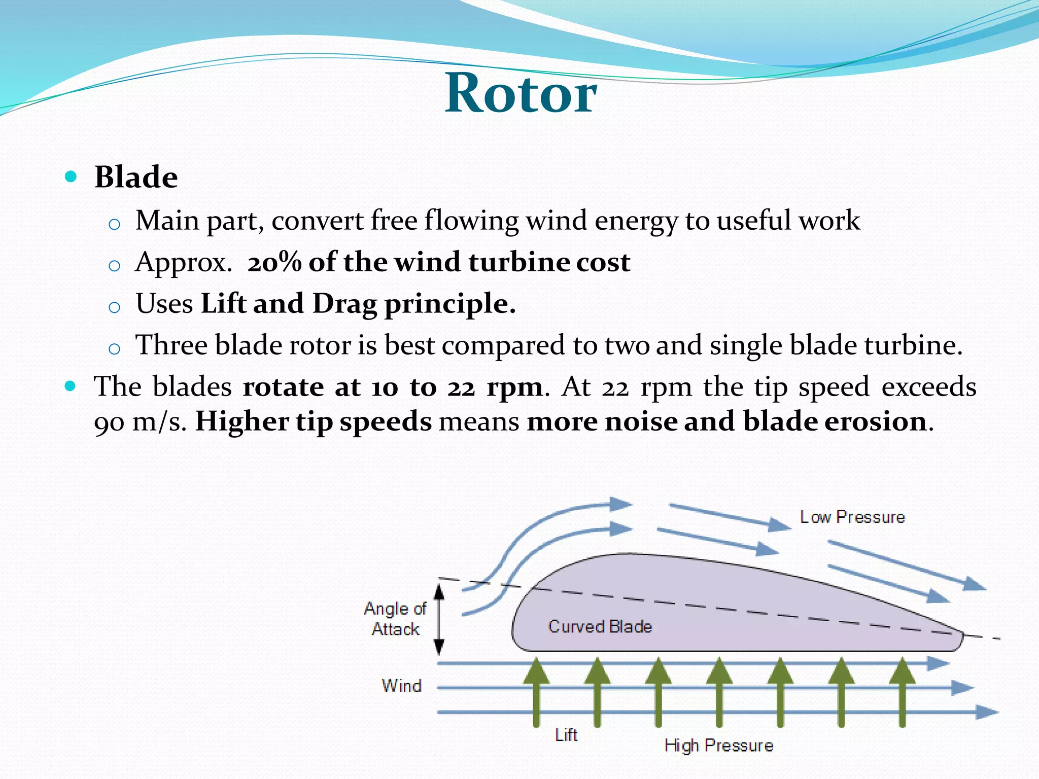
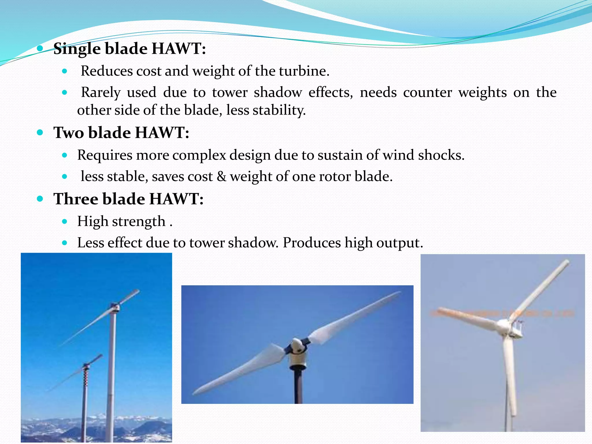

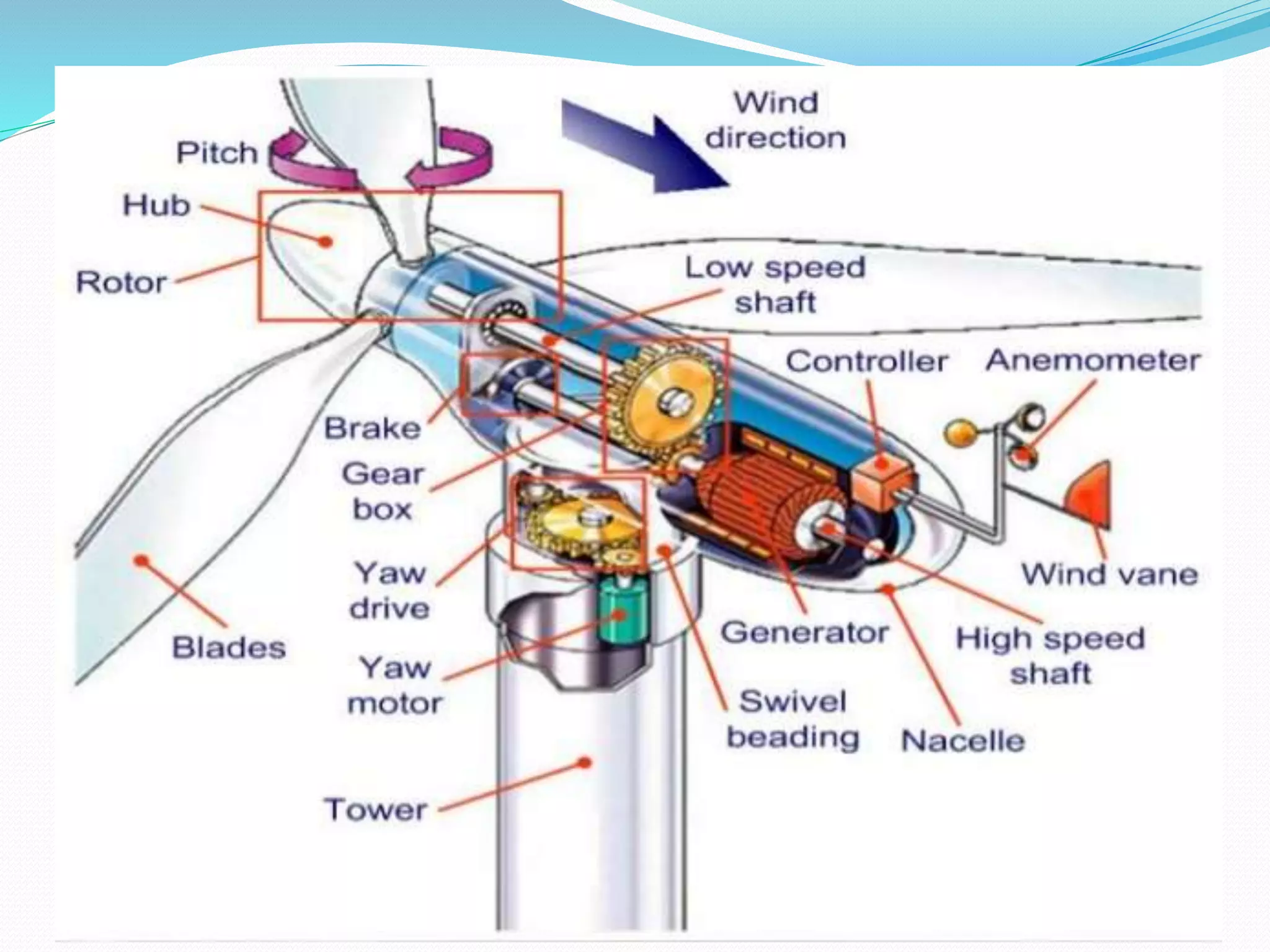


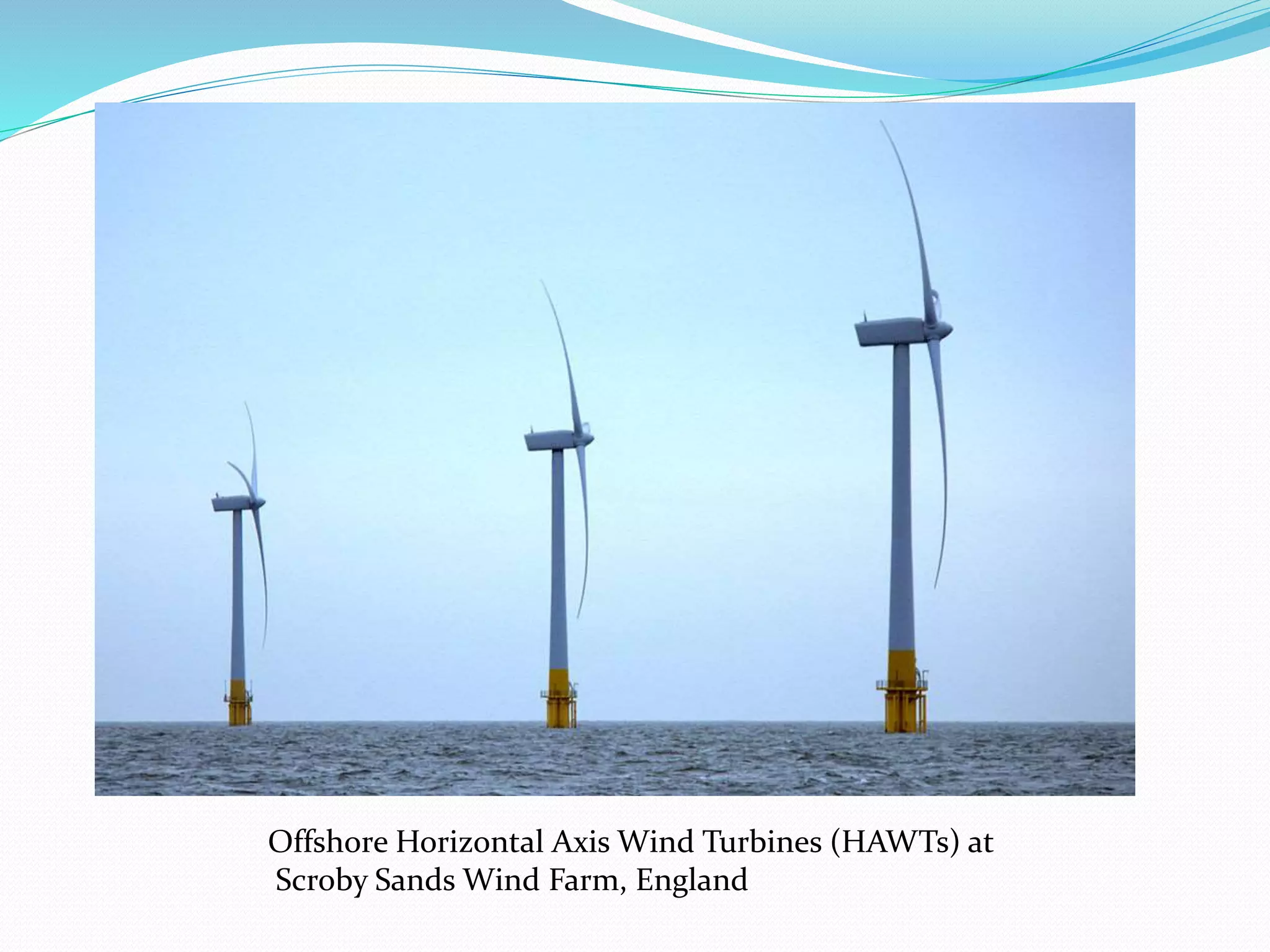


This document describes the components and operation of horizontal axis wind turbines (HAWTs). It discusses the rotor, hub, nacelle, generator, controller, yaw system, tower, and foundation. Technological evolutions including increases in turbine height, blade diameter, and power output are also summarized. Global wind capacity has grown substantially, with the current world record held by an 8 MW turbine with a 164m diameter rotor.


![EEE 483[Wind Energy ,use of wind energy].pdf](https://cdn.slidesharecdn.com/ss_thumbnails/eee483windenergy-240506111938-7f084448-thumbnail.jpg?width=640&height=640&fit=bounds)


