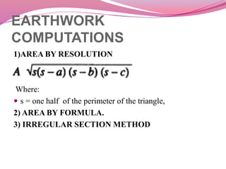
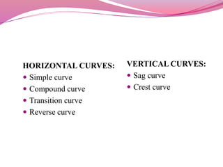
PROJECT
INTRODUCTION
 “ROAD” is defined as a formed path suitable for use by all
forms of non-guided vehicular transport.
 ROAD TRANSPORT IS ONE OF THE MOST COMMON
MODES OF TRANSPORT.
 A road is an identifiable route, way or path between two or
more places. It can vary from the most fundamental of formed
tracks through remote territory to multi-lane, high-speed.
 Users of road include buses,trucks, motorcycles, bicycles and
pedestrians. motorways through, or linking cities.
NECESSITY OF ROAD
TRANSPORT
 It facilitates the movement of men and material from one place
to another.
 The road connecting Tergaon and Madnalli is now inadequate
for the rapidly growing population. Thus, an
improved,widened road is the need of the hour.
 Educational and cultural contact can be maintained with each
other.
 It helps in the growth of trade and other economic activities in
and outside the villages and towns.
 Strategic movement in case of emergency for defense,health
issues as well as peace time is necessary.
ROAD PROJECT
 Road project deals with the planning, designing and
construction of a new road, connecting two terminus
points or a town with an existing road. The road project
consists of:
 I) Survey,
 II) Preparation of maps.
 III) Road alignment.
 IV) Earthwork.
1) SURVEY
To determine the location of a proposed road and to
collect the required data, the following road surveys are
withheld.
 Reconnaissance survey.
 Preliminary survey.
 Final location survey.
 Construction survey.
2) PREPARATION OF MAPS
 Topographical maps.
 Proposed plans
 Agricultural and industrial maps
 Population maps.
3) ROAD ALIGNMENT
 The route, along which the center line of a road is located
in the plan, is called Road Alignment.
The following points should be kept in mind while
aligning a road.
 It should ensure easy gradients and smooth curves.
 The alignment should be as short and straight as possible.
 There should be minimum cutting and banking.
4) EARTHWORK
 Earthworks can be defined as all the operations invo
lved in the loosening, removing and depositing of
earth, soil and rock.
The principal earthworks operations are :-
 Stripping vegetation and topsoil
 Loosening material in cutting and borrow pits
 Excavating material
 Loading material from cuts etc. and hauling to fills or to
spoil
EARTHWORK
COMPUTATIONS
1)AREA BY RESOLUTION
 ₌
Where:
 s = one half of the perimeter of the triangle,
2) AREA BY FORMULA.
3) IRREGULAR SECTION METHOD
ROAD GRADIENT
Gradient of a road mainly depends on:
 Nature of traffic.
 Nature of ground.
 Rainfall of the locality.
CURVES
 Curves are provided whenever a road changes its
direction from right to left or (vice versa) or change its
alignment from up to down or (vice versa). Curves are a
critical element in the pavement design
 TYPES OF CURVES
 Horizontal curves
 Vertical curves
HORIZONTAL CURVES:
 Simple curve
 Compound curve
 Transition curve
 Reverse curve
VERTICAL CURVES:
 Sag curve
 Crest curve
CH PT
COMPUTATION
CHA
INA
GE
RL
FORM
ATIO
N
LEVE
L
Dept
h of
Fill
Dept
h of
CUT
Mean
depth
of fill
Area of
fill
Mean
Dept
h of
Cut
Area
of cut
Lengt
h
Volume
Of Fill
Volume
Of Cut
CROSS SECTIONS
DESIGN
OF
CURVES
DESIGN OF VERTICAL CURVE
Velocity, V=50kmph or v=13.89m/s
Coefficient of longitudinal friction, f=0.37
Reaction time as per IRC t=2.5s
Stopping Sight Distance SSD=vt + v2/2gf
=0.278Vt + (V2/254f)
SSD=61.35m
Intermediate Sight Distance ISD=2*SSD
=122.70m
Overtaking Sight Distance OSD=vbt+vbT+2s+vT
=0.278Vbt+0.278Vb+2s+.0278VT
Where Vb=V-16kmph
S=0.2Vb+6=12.8m
For V=50kmph, A=4kmph/s
T=√(14.4s/A)
=6.79sec
OSD= 207.74m
For 1st stretch i.e. at 185m chainage
n1=1in50
n2=1in60
N=n1-(-n2)
=1/50+1/60
=0.0367
DESIGN OF SUMMIT CURVE
For SSD, Considering L>SSD
L=NS2/4.4
=0.0365*61.352/4.4
=31.39m<SSD
Now L<SSD,
L=2S-4.4/N
=2*61.35-4.4/.0365
=2.81m
Now Considering OSD, L>OSD
L=NS2/9.6
=0.0365*207.752/9.6
=164.98m<OSD
For L<OSD
L=2S-9.6/N
=2*207.75-9.6/.0365
=153.89m
Provide Length of SUMMIT CURVE= 157m
DESIGN OF VALLEY CURVE
At chainage 1140m
n1=1in50
n2=1in30
N=-n1-n2
=-1/50-1/30
=-0.053
When L>SSD,
Length of Valley Curve L=NS2/(2h1+2Stanα)
Where h1=average height of light beam=0.75m
α=beam angle=1ͦ
L=NS2/(1.5+.035S)
L=0.053*61.352/(1.5+0.035*61.35)
=55.04m<SSD
Now L<SSD
L=2S-(1.5+0.035S)/N
=2*61.35-(1.5+0.035*61.35)/0.053
=53.88m
Provide Length of VALLEY CURVE L=55m
DESIGN OF PAVEMENT CROSS SECTION
Providing the Camber of 1in50
A = P (1+r)n+10
D = 200
n = 3
r = 8%
A = 200(1+0.08)13
A =544
Curve E = 330mm
For 330mm = 1 MSA
For 1 MSA
Total thickness = 375mm
Wearing curve = 20mm
Granular base = 225mm
Highway

Highway

  • 1.
  • 2.
    INTRODUCTION  “ROAD” isdefined as a formed path suitable for use by all forms of non-guided vehicular transport.  ROAD TRANSPORT IS ONE OF THE MOST COMMON MODES OF TRANSPORT.  A road is an identifiable route, way or path between two or more places. It can vary from the most fundamental of formed tracks through remote territory to multi-lane, high-speed.  Users of road include buses,trucks, motorcycles, bicycles and pedestrians. motorways through, or linking cities.
  • 3.
    NECESSITY OF ROAD TRANSPORT It facilitates the movement of men and material from one place to another.  The road connecting Tergaon and Madnalli is now inadequate for the rapidly growing population. Thus, an improved,widened road is the need of the hour.  Educational and cultural contact can be maintained with each other.  It helps in the growth of trade and other economic activities in and outside the villages and towns.  Strategic movement in case of emergency for defense,health issues as well as peace time is necessary.
  • 4.
    ROAD PROJECT  Roadproject deals with the planning, designing and construction of a new road, connecting two terminus points or a town with an existing road. The road project consists of:  I) Survey,  II) Preparation of maps.  III) Road alignment.  IV) Earthwork.
  • 5.
    1) SURVEY To determinethe location of a proposed road and to collect the required data, the following road surveys are withheld.  Reconnaissance survey.  Preliminary survey.  Final location survey.  Construction survey.
  • 6.
    2) PREPARATION OFMAPS  Topographical maps.  Proposed plans  Agricultural and industrial maps  Population maps.
  • 7.
    3) ROAD ALIGNMENT The route, along which the center line of a road is located in the plan, is called Road Alignment. The following points should be kept in mind while aligning a road.  It should ensure easy gradients and smooth curves.  The alignment should be as short and straight as possible.  There should be minimum cutting and banking.
  • 8.
    4) EARTHWORK  Earthworkscan be defined as all the operations invo lved in the loosening, removing and depositing of earth, soil and rock. The principal earthworks operations are :-  Stripping vegetation and topsoil  Loosening material in cutting and borrow pits  Excavating material  Loading material from cuts etc. and hauling to fills or to spoil
  • 9.
    EARTHWORK COMPUTATIONS 1)AREA BY RESOLUTION ₌ Where:  s = one half of the perimeter of the triangle, 2) AREA BY FORMULA. 3) IRREGULAR SECTION METHOD
  • 10.
    ROAD GRADIENT Gradient ofa road mainly depends on:  Nature of traffic.  Nature of ground.  Rainfall of the locality.
  • 11.
    CURVES  Curves areprovided whenever a road changes its direction from right to left or (vice versa) or change its alignment from up to down or (vice versa). Curves are a critical element in the pavement design  TYPES OF CURVES  Horizontal curves  Vertical curves
  • 12.
    HORIZONTAL CURVES:  Simplecurve  Compound curve  Transition curve  Reverse curve VERTICAL CURVES:  Sag curve  Crest curve
  • 13.
  • 16.
  • 17.
    CHA INA GE RL FORM ATIO N LEVE L Dept h of Fill Dept h of CUT Mean depth offill Area of fill Mean Dept h of Cut Area of cut Lengt h Volume Of Fill Volume Of Cut
  • 18.
  • 19.
  • 20.
    DESIGN OF VERTICALCURVE Velocity, V=50kmph or v=13.89m/s Coefficient of longitudinal friction, f=0.37 Reaction time as per IRC t=2.5s Stopping Sight Distance SSD=vt + v2/2gf =0.278Vt + (V2/254f) SSD=61.35m Intermediate Sight Distance ISD=2*SSD =122.70m Overtaking Sight Distance OSD=vbt+vbT+2s+vT =0.278Vbt+0.278Vb+2s+.0278VT Where Vb=V-16kmph S=0.2Vb+6=12.8m For V=50kmph, A=4kmph/s T=√(14.4s/A) =6.79sec OSD= 207.74m For 1st stretch i.e. at 185m chainage n1=1in50 n2=1in60 N=n1-(-n2) =1/50+1/60 =0.0367
  • 21.
    DESIGN OF SUMMITCURVE For SSD, Considering L>SSD L=NS2/4.4 =0.0365*61.352/4.4 =31.39m<SSD Now L<SSD, L=2S-4.4/N =2*61.35-4.4/.0365 =2.81m Now Considering OSD, L>OSD L=NS2/9.6 =0.0365*207.752/9.6 =164.98m<OSD For L<OSD L=2S-9.6/N =2*207.75-9.6/.0365 =153.89m Provide Length of SUMMIT CURVE= 157m
  • 22.
    DESIGN OF VALLEYCURVE At chainage 1140m n1=1in50 n2=1in30 N=-n1-n2 =-1/50-1/30 =-0.053 When L>SSD, Length of Valley Curve L=NS2/(2h1+2Stanα) Where h1=average height of light beam=0.75m α=beam angle=1ͦ L=NS2/(1.5+.035S) L=0.053*61.352/(1.5+0.035*61.35) =55.04m<SSD Now L<SSD L=2S-(1.5+0.035S)/N =2*61.35-(1.5+0.035*61.35)/0.053 =53.88m Provide Length of VALLEY CURVE L=55m
  • 23.
    DESIGN OF PAVEMENTCROSS SECTION Providing the Camber of 1in50 A = P (1+r)n+10 D = 200 n = 3 r = 8% A = 200(1+0.08)13 A =544 Curve E = 330mm For 330mm = 1 MSA For 1 MSA Total thickness = 375mm Wearing curve = 20mm Granular base = 225mm