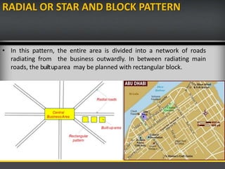
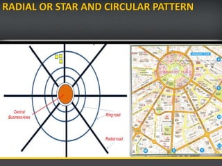
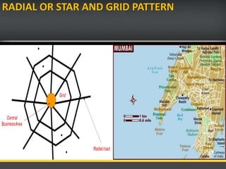
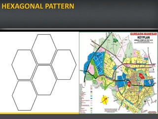
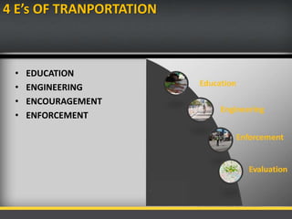
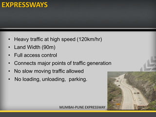
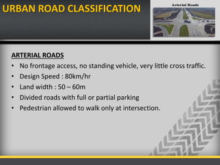
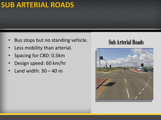
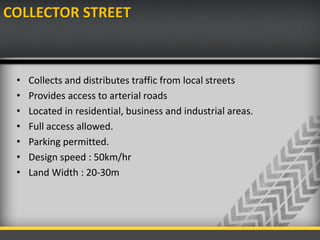
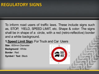
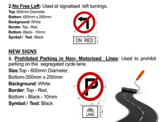
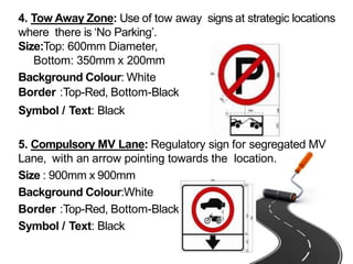
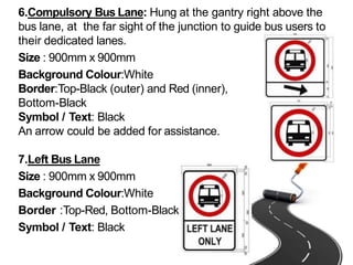
This document provides information about transportation engineering and the historical development of roads. It discusses early footpaths and animal-drawn vehicles, and the development of Roman, French, British, and Indian road networks. It also covers classifications of highways, road patterns, the 4 Es of transportation, and urban road classification systems including arterial, sub-arterial, collector, local, and cul-de-sac streets.
Friction Considerations : The friction of skid resistance between vehicle tyre and pavement surface is one of the factors determining the operating speed and the minimum distance requires for stopping of vehicles.
Unevenness : The longitudinal profile of the road pavement has to be even' in order to provide a good riding comfort to fast moving vehicles
Light Reflecting Characteristics : Night visibility depends upon the colour and light reflecting characteristics of the pavement surface. The glare caused by the reflection of head lights is considerably high on wet pavement surface than on the dry pavement.
Drainage of Surface Water
Alignment: The position or the layout of the central line of the highway on the ground is called the alignment.
Highway Alignment includes both
a) Horizontal alignment includes straight and curved paths, the deviations and horizontal curves.
b) Vertical alignment includes changes in level, gradients and vertical curves.
Highway Engineering for BE Civil Engineering Students
History of Roads in India, IRC, CRRI, Classification of Roads, Three 20 year Road Development Plans, Road patterns, Accident Studies,
Highway planning and alignment: Different modes of transportation – historical Development of road construction- Highway Development in India –Classification of roads- Road pattern
– Highway planning in India- Highway alignment - Engineering Surveys for alignment – Highway Project- Important Transport/Highway related agencies in India. PMGSY project.
Introduction about IRC, NRRDA
Transportation Engineering
Brief study on measurement of spot speed with the help of enoscope for diploma engineering students of civil engineering stream.
DAVV IET_ TraNSPORTATION [PPT LECTURES ALL 501.pptxprtaap1
(Established by the Government of India under NITSER Act,)
P.O. ICHCHHANATH, SURAT-395 007, GUJARAT, INDIA
Website: http://www.svnit.ac.in
Advt No. Estt. /2022/Gr_A1/2002 Date: October 17, 2022
RECRUITMENT FOR NON-TEACHING POSITIONS
Sardar Vallabhbhai National Institute of Technology Surat (SVNIT) was established by the
Government of India by an Act of Parliament, offering UG, PG and Ph.D. Programs in Engineering/
Technology and Sciences. The Institute is in search of bright, dynamic, experienced, qualified, and
suitable Indian Nationals to cater the Institute’s requirement. The Institute invites online
applications for the following Non-teaching positions on direct recruitment in various departments/
sections of the Institute:
Sl.
No
Name of the Post (s)
& Specialization/
Relevant Field
Pay Level
(as per 7 CPC)
No of Vacant Posts* Total* Upper
Age
Limit
UR SC ST OBCNCL
EWS
1 Librarian Pay Level 14
[PB-4 & GP Rs
10000]
1 - - - - 1 56
2 Scientific Officer /
Technical Officer
(MIS)
Pay Level 10
[PB-3 & GP Rs
5400]
1 - - - - 1 35
3 Executive Engineer
(Civil-01, Electrical-
01)
Pay Level 10
[PB-3 & GP Rs
5400]
2 - - - - 2 35
Total 4 0 0 0 0 4
*One post will be filled up from the identified person with benchmark disabilities, if found suitable
The eligibility criteria for the above posts is as per Recruitment Rules of NITs (2019) and as
updated from time to time by Ministry of Education, Govt. of India. For details regarding the
online Application Form, Educational Qualifications, Experience, other requirements and terms &
conditions for these positions, please visit the Institute website http://www.svnit.ac.in. The
number of Posts may vary at the time of final selection / recruitment.
The recruitment notice for the post advertised vide advertisement no. Estt./2021/Gr_A/3051
dated 02.03.2021 & Estt./2021/2021/EE/678 dated 07.06.2021 for which the recruitment process
has not been completed is cancelled vide Notice No.E/Rect.(2021)/1165 dated 14.10.2022. The
interested applicant who has applied earlier may apply afresh.
The interested candidates may apply online through the Institute website http://www.svnit.ac.in
and send the filled in downloaded online application form duly singed alongwith self-attested
documents viz. relevant testimonials, certificates, payment receipts etc. by speed/ registered
posts to the Deputy Registrar (Establishment), Sardar Vallabhbhi National Institute of
Technology, Ichchhanath, Dumas Road, Surat – 395 007, Gujarat, The applications received
through any other mode shall not be accepted and summarily rejected. The last date for
submission of online application is December 02, 2022 till 5.00 p.m. and receipt of
downloaded signed completed application at SVNIT Surat is December 12, 2022.
-sd/-
REGISTRAR
1
(Established by the Government of India under NITSER Act,)
P.O. ICHCHHANATH, SURAT-395 007, GUJARAT, INDIA
Website: http://www.svnit.ac.in
Advt No. Estt. /2022/Gr_A1/2002 Date: October 17, 2022
RECRUITMENT FOR NON-TEACHING P
Transportation engineering, primarily involves planning, design, construction, maintenance, and operation of transportation facilities. The facilities support air, highway, railroad, pipeline, water, and even space transportation.
CFD Simulation of By-pass Flow in a HRSG module by R&R Consult.pptxR&R Consult
CFD analysis is incredibly effective at solving mysteries and improving the performance of complex systems!
Here's a great example: At a large natural gas-fired power plant, where they use waste heat to generate steam and energy, they were puzzled that their boiler wasn't producing as much steam as expected.
R&R and Tetra Engineering Group Inc. were asked to solve the issue with reduced steam production.
An inspection had shown that a significant amount of hot flue gas was bypassing the boiler tubes, where the heat was supposed to be transferred.
R&R Consult conducted a CFD analysis, which revealed that 6.3% of the flue gas was bypassing the boiler tubes without transferring heat. The analysis also showed that the flue gas was instead being directed along the sides of the boiler and between the modules that were supposed to capture the heat. This was the cause of the reduced performance.
Based on our results, Tetra Engineering installed covering plates to reduce the bypass flow. This improved the boiler's performance and increased electricity production.
It is always satisfying when we can help solve complex challenges like this. Do your systems also need a check-up or optimization? Give us a call!
Work done in cooperation with James Malloy and David Moelling from Tetra Engineering.
More examples of our work https://www.r-r-consult.dk/en/cases-en/
Sachpazis:Terzaghi Bearing Capacity Estimation in simple terms with Calculati...Dr.Costas Sachpazis
Terzaghi's soil bearing capacity theory, developed by Karl Terzaghi, is a fundamental principle in geotechnical engineering used to determine the bearing capacity of shallow foundations. This theory provides a method to calculate the ultimate bearing capacity of soil, which is the maximum load per unit area that the soil can support without undergoing shear failure. The Calculation HTML Code included.
Overview of the fundamental roles in Hydropower generation and the components involved in wider Electrical Engineering.
This paper presents the design and construction of hydroelectric dams from the hydrologist’s survey of the valley before construction, all aspects and involved disciplines, fluid dynamics, structural engineering, generation and mains frequency regulation to the very transmission of power through the network in the United Kingdom.
Author: Robbie Edward Sayers
Collaborators and co editors: Charlie Sims and Connor Healey.
(C) 2024 Robbie E. Sayers
NO1 Uk best vashikaran specialist in delhi vashikaran baba near me online vas...Amil Baba Dawood bangali
Contact with Dawood Bhai Just call on +92322-6382012 and we'll help you. We'll solve all your problems within 12 to 24 hours and with 101% guarantee and with astrology systematic. If you want to take any personal or professional advice then also you can call us on +92322-6382012 , ONLINE LOVE PROBLEM & Other all types of Daily Life Problem's.Then CALL or WHATSAPP us on +92322-6382012 and Get all these problems solutions here by Amil Baba DAWOOD BANGALI
#vashikaranspecialist #astrologer #palmistry #amliyaat #taweez #manpasandshadi #horoscope #spiritual #lovelife #lovespell #marriagespell#aamilbabainpakistan #amilbabainkarachi #powerfullblackmagicspell #kalajadumantarspecialist #realamilbaba #AmilbabainPakistan #astrologerincanada #astrologerindubai #lovespellsmaster #kalajaduspecialist #lovespellsthatwork #aamilbabainlahore#blackmagicformarriage #aamilbaba #kalajadu #kalailam #taweez #wazifaexpert #jadumantar #vashikaranspecialist #astrologer #palmistry #amliyaat #taweez #manpasandshadi #horoscope #spiritual #lovelife #lovespell #marriagespell#aamilbabainpakistan #amilbabainkarachi #powerfullblackmagicspell #kalajadumantarspecialist #realamilbaba #AmilbabainPakistan #astrologerincanada #astrologerindubai #lovespellsmaster #kalajaduspecialist #lovespellsthatwork #aamilbabainlahore #blackmagicforlove #blackmagicformarriage #aamilbaba #kalajadu #kalailam #taweez #wazifaexpert #jadumantar #vashikaranspecialist #astrologer #palmistry #amliyaat #taweez #manpasandshadi #horoscope #spiritual #lovelife #lovespell #marriagespell#aamilbabainpakistan #amilbabainkarachi #powerfullblackmagicspell #kalajadumantarspecialist #realamilbaba #AmilbabainPakistan #astrologerincanada #astrologerindubai #lovespellsmaster #kalajaduspecialist #lovespellsthatwork #aamilbabainlahore #Amilbabainuk #amilbabainspain #amilbabaindubai #Amilbabainnorway #amilbabainkrachi #amilbabainlahore #amilbabaingujranwalan #amilbabainislamabad
Forklift Classes Overview by Intella PartsIntella Parts
Discover the different forklift classes and their specific applications. Learn how to choose the right forklift for your needs to ensure safety, efficiency, and compliance in your operations.
For more technical information, visit our website https://intellaparts.com
Automobile Management System Project Report.pdfKamal Acharya
The proposed project is developed to manage the automobile in the automobile dealer company. The main module in this project is login, automobile management, customer management, sales, complaints and reports. The first module is the login. The automobile showroom owner should login to the project for usage. The username and password are verified and if it is correct, next form opens. If the username and password are not correct, it shows the error message.
When a customer search for a automobile, if the automobile is available, they will be taken to a page that shows the details of the automobile including automobile name, automobile ID, quantity, price etc. “Automobile Management System” is useful for maintaining automobiles, customers effectively and hence helps for establishing good relation between customer and automobile organization. It contains various customized modules for effectively maintaining automobiles and stock information accurately and safely.
When the automobile is sold to the customer, stock will be reduced automatically. When a new purchase is made, stock will be increased automatically. While selecting automobiles for sale, the proposed software will automatically check for total number of available stock of that particular item, if the total stock of that particular item is less than 5, software will notify the user to purchase the particular item.
Also when the user tries to sale items which are not in stock, the system will prompt the user that the stock is not enough. Customers of this system can search for a automobile; can purchase a automobile easily by selecting fast. On the other hand the stock of automobiles can be maintained perfectly by the automobile shop manager overcoming the drawbacks of existing system.
2. WHAT IS TRANSPORTATION EGINEERING?
Transportation engineering is the application of the
principles of engineering, planning, analysis, and design
to the disciplines comprising transportation: its vehicles,
its physical infrastructure, safety in travel,
environmental impacts, and energy usage.
• Objective
• Safe, efficient, economical transportation facilities for travel of
passenger & transportation of goods.
3. HISTORICAL DEVELOPMENT OF ROADS
EARLY DEVELOPMENT
• The oldest mode of travel was on the foot-paths.
• Animals were also used to transport men and materials.
• Later simple animal drawn vehicles were developed and this
became a common and popular mode of transportation for very
along period after the invention of wheel.
• This brought up the necessity of providing a hard surface for
these wheeled vehicles to move on.
• Such a hard surface is believed to have existed in the period of
about 3500 B.C.
4. ROMAN ROADS(312 B.C.)
FEATURES OF ROMAN ROADS
• An earthed road with a graveled surface.
• They were build straight without any gradient.
• The soft soil from top was removed till the hard stratum was
reached.
• The total thickness of road section worked out as high as 750
mm to 1200 mm.
6. FRENCH ROADS OR TRESAGUET ROADS
(1716-1796)
• The next major development in the road construction occurred
during the regime of Napoleon.
• The pavement used 200 mm pieces of stone of a more compact
form and shaped such that they had at least one at side which
was placed on a compact formation.
• Smaller pieces of broken stones were then compacted into the
spaces between larger stones to provide a level surface.
• Finally the running layer was made with a layer of 25 mm sized
broken stone.
8. TELFORD CONSTRUCTION(1757-1834)
• The foundation was prepared for a road with width of 9 m and
it was levelled.
• Large size stones of width equal to 40 mm and depth 170 to 220
mm were then laid.
• After filling the spaces between foundation stones, two layers
of stones having compacted thickness of 100 and 50 mm
respectively laid in the center of 5.4 m. of width.
• The top layer of road was made of 40 mm thick binding layer of
gravel.
10. BRITISH OR MACADAM ROADS(1756-
1836)
• The British engineer John Macadam introduced what can be
considered as the first scientific road construction method.
• Stone size was an important element of Macadam road. By
empirical observation of many roads, he came to realize that
250 mm layers of well compacted broken angular stone would
provide the same strength and stiffness and a better running
surface than an expensive pavement founded on large stone
blocks.Thus he introduced an economical method of road
construction.
12. DIFFERENCE BETWEEN TELFORD AND
MACADAM CONSTRUCTION
Parameter Telford Macadam
Subgrade slope Horizontal 1 in 36
Foundation stone From 170 mm to 220mm. From 50 mm to 100mm.
Basecourse Two layers of broken
stones
Onelayer of broken stone
Surface course 40 mm thick with slope 1
in 45
50 mm thick with slope 1in
36
Thickness of crosssection 410 mm at center and
350 at edge
Uniform 250 mm only.
13. FIRST 20 YEARS ROAD PLAN OR NAGPUR ROAD
PLAN(1943-1963)
• The target road length 16 km per 100 square km area of the
country.
• The conference of chief engineer held at Nagpur in 1943
finalized the first 20-years road development plan for India
called Nagpur road plan.
• Road network was classified into five categories.
• The responsibility of construction maintenance of NH was
assign to central govt.
• The target road length was 5,32,700 km at the end of 1961.
14. SECOND 20 YEARS ROAD PLAN OR BOMBAY
ROAD PLAN(1961-1981)
• Target road length of 10,57,330 km or about 32 km per hundred
sq km area.
• Rs. 5200 crores for 1980-81 was envisaged for this plan based
on 1958 price level.
• 1600 km of Express ways included.
• Total length of all category roads achieved by 1974 – 11.45 lakhs
km, road density – 34.8 km per 100 sq.km area.
15. THIRD 20 YEARS ROAD PLAN OR LUCKOW ROAD
PLAN(1981-2001)
• Prepared by Ministry of Shipping & transport co-operation with
no. of organisation.
• Growth pattern envisaged in various fields.
• Aim at increasing road length from 15,02,700 km in the yr 1981
to 27,02,00 km by the year 2001.
• Increase in road density from 46 km per 100 sq km in 1981, to
82 km per 100 sq km in 2001.
16. JAYAKAR COMMITTEE(1927)
• In 1927,Indian road development committee was appointed by the
government with M.R. Jayakar as chairman.
• Road development in the country should be made as a national
interest since local govt. do not have financial and technical capacity
for road development.
• An extra tax should be levied on petrol from road users to create the
road development fund.
• To establish a semi-official ,technical institution to pool technical
knowledge, sharing of ideas and to act as an advisory body.
• To create a national level institution to carry research , development
works and consultation.
17. INDIAN ROAD CONGRESS(1934)
• Central semi official body known as IRC was formed in 1934.
• To provide national forum for regular pooling of experience
and ideas on matters related to construction and maintenance
of highways.
• It is a active body controlling the specification,
standardization and recommendations on materials,
design of roads and bridges.
• It publishes journals, research publications and standard
specifications guide lines.
• To provide a platform for expression of professional
• opinion on matters relating to roads and road transport.
18. MOTOR VEHICLE ACT(1939)
• Road development should be made a national interest since the
provincial and local govt. do not have financial and technical
capacity for road development.
• Levy extra tax on petrol from road users to create the road
development fund.
• To establish a semi-official ,technical institution to pool
technical knowledge, sharing of ideas and to act as an advisory
body.
• To create a national level institution to carry research ,
development works and consultation.
• Revised 1988.
19. GOLDEN QUADILATERAL
The Golden Quadrilateral (GQ) is a national highway network connecting
most of the major industrial, agricultural and cultural centres of India. It
forms a quadrilateral connecting the four major metro cities of India,i.e.
Delhi (north), Kolkata (east), Mumbai (west) and Chennai (south).
Major highlights of the Golden Quadrilateral
• It is the largest highway project completed in India.
• It is the fifth longest highway project in the world.
• The overall length of the Golden quadrilateral is 5,846km.
• The Golden Quadrilateral passes through 13 states of India.
• The project was estimated to cost INR600bn but was one such project
which was completed at about half of the estimated costs at
INR308.58bn.
20. No. Segment Total Length (km)
1. Delhi-Kolkata 1,453 km (903 mi)
2. Chennai-Mumbai 1,290 km (800 mi)
3. Kolkata-Chennai 1,684 km (1,046 mi)
4. Mumbai-Delhi 1,419 km (882 mi)
Total 5,846 km (3,633 mi)
21. ROAD PATTERNS
The various road patterns may be classified as:
• Rectangular or Block pattern
• Radial or star and block pattern
• Radial or star and circular pattern
• Radial or star and grid pattern
• Hexagonal pattern
22. RECTANGULAR OR BLOCK PATTERN
• In this pattern, the whole area is divided into rectangular blocks of
plots, with streets intersecting at right angles.
23. RADIAL OR STAR AND BLOCK PATTERN
• In this pattern, the entire area is divided into a network of roads
radiating from the business outwardly. In between radiating main
roads, the builtuparea may be planned with rectangular block.
28. CLASSIFICATION OF HIGHWAYS
Depending on weather
• All weather roads
• Fair weather roads
Depending the type of Carriage way
• Paved roads(WBM)
• Unpaved roads(earth road or gravel road)
Depending upon the pavement surface
• Surfaced roads(bituminous or cement concrete road)
• Unsurfaced roads
29. CLASSIFICATION OF HIGHWAYS
Based on the Traffic Volume
• Heavy
• Medium
• Light
Based on Load or Tonnage
• Class 1 or Class 2 etc or Class A , B etc Tonnes per day
Based on location and function ( Nagpur road plan )
• National highway (NH)
• State highway (SH)
• Major district road (MDR)
• Other district road (ODR)
• Village road (VR)
30. CLASSIFICATION OF HIGHWAYS BASED ON
MODIFIED SYSTEM
Primary
• Expressways
• National Highways
Secondary
• State Highways(SH)
• Major District Roads(MDR)
Tertiary
• Other District Roads(ODR)
• Village Roads(VR)
31. EXPRESSWAYS
• Heavy traffic at high speed (120km/hr)
• Land Width (90m)
• Full access control
• Connects major points of traffic generation
• No slow moving traffic allowed
• No loading, unloading, parking.
MUMBAI-PUNE EXPRESSWAY
32. URBAN ROAD CLASSIFICATION
ARTERIAL ROADS
• No frontage access, no standing vehicle, very little cross traffic.
• Design Speed : 80km/hr
• Land width : 50 – 60m
• Divided roads with full or partial parking
• Pedestrian allowed to walk only at intersection.
33. SUB ARTERIAL ROADS
• Bus stops but no standing vehicle.
• Less mobility than arterial.
• Spacing for CBD: 0.5km
• Design speed: 60 km/hr
• Land width: 30 – 40 m
34. COLLECTOR STREET
• Collects and distributes traffic from local streets
• Provides access to arterial roads
• Located in residential, business and industrial areas.
• Full access allowed.
• Parking permitted.
• Design speed : 50km/hr
• Land Width : 20-30m
35. LOCAL STREET
• Design Speed : 30km/hr.
• Land Width : 10 – 20m.
• Primary access to residence, business or other abutting
property
• Less volume of traffic at slow speed
• Unrestricted parking, pedestrian movements. (with frontage
access, parked vehicle, bus stops and no waiting restrictions)
36. CUL-DE-SAC
• Dead End Street with only one entry access for entry and exit.
• Recommended in Residential areas
37. DRIVEWAY
• A driveway is a type of private road for local access to one or a
small group of structures, and is owned and maintained by an
individual or group.
• Driveways are commonly used as paths to private garages, fuel
stations, or houses.
39. HIGHWAY ALIGNMENT
• The position or lay out of centre line of the highway on
the ground is called the alignment.
• It includes straight path, horizontal deviation and
curves.
• Due to improper alignment , the disadvantages are,
Increase in construction
Increase in maintenance cost
Increase in vehicle operation cost
Increase in accident cost
• Once the road is aligned and constructed, it is not easy
to change the alignment due to increase in cost of
adjoining land and construction of costly structure.
40.
41. REQUIREMENTS OF HIGHWAY ALIGNMENT
• Short- desirable to have a short alignment between two
terminal stations.
• Easy- easy to construct and maintain the road with
minimum problem also easy for operation of vehicle.
• Safe- safe enough for construction and maintenance from
the view point of stability of natural hill slope, embankment
and cut slope also safe for traffic operation.
• Economical- total cost including initial cost, maintenance
cost and vehicle operation cost should be minimum.
42. HIGHWAY GEOMETRIC DESIGN
• The geometric design of a highway deals with
the dimensions and layout of visible features of
the highway such as alignment, sight distance
and intersection.
43. DESIGN CONTROLS AND CRITERIA
• Design speed
• Topography
• Traffic factors
• Design hourly volume and capacity
• Environmental and other factors
Design speed
• In India different speed standards have been assigned for different
class of road
• Design speed may be modified depending upon the terrain
conditions.
44. HIGHWAY CROSS SECTION ELEMENTS
• Carriageway
• Shoulder
• Roadway width
• Right of way
• Building line
• Control line
• Median
• Camber/ cross slope
• Crown
• Side slope
• Kerb
• Guard rail
• Side drain
• Other facilities
45. CARRIAGEWAY
• It is the travel way which is used for movement of vehicle, it
takes the vehicular loading .
• It may be cement concrete road or bituminous pavement.
• Width of carriageway is determined on the basis of the width
of the vehicle and the minimum side clearance for safety.
• As per IRC specification, the maximum width of vehicle is
2.44m,minimum clearance of 0.68m in case of single lane
and 1.02m in case of double lane.
46. WIDTH OF CARRIAGEWAY
SL. NO. Class of road Width of carriageway in ‘m’
1 Single lane 3.75
2 Two lane without raised kerbs 7.0
3 Two lane with raised kerbs 7.5
4 Intermediate lane 5.5
5 Multilane pavement 3.5/lane
47.
48. SHOULDER
• It is provided along the road edge to serve as an emergency
lane for vehicle.
• It act as a service lane for vehicles that have broken down.
• The minimum shoulder width of 4.6 m so that a truck stationed at
the side of the shoulder would have a clearance of 1.85m from the
pavement edge.
• IRC recommended the minimum shoulder width is 2.5 m
• It should have sufficient load bearing capacity even in wet weather.
• The surface of the should be rougher than the traffic lanes so that
vehicles are discouraged to use the shoulder as a regular traffic.
• The colour should be different from that of the pavement
so as to be distinct.
49.
50.
51. RIGHT OF WAY
• It is the total area of land acquired for the road along its
alignment.
• It depends on the importance of the road and possible
future development.
• It is desirable to acquire more width of land as the cost of
adjoining land invariably increases very much , soon after the
new highway is constructed.
52.
53. TRAFFIC SEPERATORS OR MEDIAN
• The main function is to prevent head on collision between
the vehicle moving in opposite direction.
• Channelize traffic into streams at intersection.
• Segregate slow traffic and to protect pedestrians.
• IRC recommends a minimum desirable width of 5 m and may be
reduce to 3 m where land is restricted.
• The minimum width of median in urban area is 1.2m.
54.
55. CROSS SLOPE OR CAMBER
• It is the slope provided to the road surface in the transverse
direction to drain off the rain water from the road surface.
• To prevent the entry of surface water into the subgrade soil
through pavement.
• To prevent the entry of water into the bituminous pavement
layer.
• To remove the rain water from the pavement surface as
quick as possible and to allow the pavement to get dry
soon after the rain.
• It is expressed as a percentage or 1V:Nh.
• It depends on the pavement surface and amount of rainfall.
56. KERB
• It indicates the boundary between the pavement and shoulder.
• It is desirable to provide kerbs in urban areas.
57.
58. GUARD RAIL
• It is provided at the edge of the shoulder when the road is
constructed on a fill exceeds 3 m.
• It is also provided on horizontal curve so as to provide a better
night visibility of the curves under the head light of the vehicle.
59.
60. ROAD MARGINS
Parking lane:
• These are provided on urban roads to allow kerb parking.
• As far as possible only parallel parking should be allowed as it is safer
for moving vehicle.
• It should have sufficient width say 3m .
Lay bay:
• These are provided near the public conveniences with guide map
to enable driver to stop clear off the carriageway.
• It has 3m width,30m length with 15m end tapers on both sides.
Bus bays:
• These may be provided by recessing the kerb to avoid conflict
with moving traffic.
• It is located atleast 75m away from the intersection.
61. Frontage road:
• These are provided to give access to properties along an
important highway with control access to express way or free
way
• It may run parallel to the highway and are isolated by separator.
Driveway:
• It connect the highway with commercial establishment like fuel
stations, service stations etc…
• It should be located away from the intersection.
Cycle track:
• It provided in urban areas when the volume of cycle traffic on the
road
• is very high.
• A minimum width of 2m is provided for cycle track.
Footpath:
• These are provided in urban areas when the vehicular as well
as pedestrian traffic are heavy.
• Toprotect the pedestrian and decrease accident.
• Minimum width of 1.5m is provided.
62.
63.
64.
65. SIGHT DISTANCE
• Sight distance available from a point is the actual distance
along the road surface, which a driver from a specified height
above the carriageway has visibility of stationary or moving
objects.
OR
• It is the length of road visible ahead to the driver at any
instance.
66. TYPES OF SIGHT DISTANCE
• Stopping or absolute minimum sight
distance(SSD)
• Safe overtaking or passing sight distance (OSD)
• Safe sight distance for entering into uncontrolled intersection.
• Intermediate sight distance
• Head light sight distance
67. Stopping sight distance:
• The minimum sight distance available on a highway at any spot should be
of sufficient length to stop a vehicle traveling at design speed, safely
without collision with any other obstruction.
Over taking sight distance:
• The minimum distance open to the vision of the driver of a vehicle
intending to overtake slow vehicle ahead with safety against the traffic of
opposite direction is known as the minimum overtaking sight distance
(OSD) or the safe passing sight distance.
Sight distance at intersection:
• Driver entering an uncontrolled intersection (particularly unsignalised
Intersection) has sufficient visibility to enable him to take control of his
vehicle and to avoid collision with another vehicle.
68. Intermediate sight distance:
• This is defined as twice the stopping sight distance. When
overtaking sight distance can not be provided, intermediate
sight distance is provided to give limited overtaking
opportunities to fast vehicles.
Head light sight distance:
• This is the distance visible to a driver during night driving under
the illumination of the vehicle head lights. This sight distance is
critical at up-gradients and at the ascending stretch of the valley
curves.
69. STOPPING SIGHT DISTANCE
• SSD is the minimum sight distance available on a highway at any
spot having sufficient length to enable the driver to stop a
vehicle traveling at design speed, safely without collision with
any other obstruction.
70.
71. FACTORS AFFECTING SSD
• Total reaction time of driver
• Speed of vehicle
• Efficiency of brakes
• Frictional resistance between road and tyre
• Gradient of road
72. “PIEV” THEORY
Total reaction time of driver is split into four parts:
• P-perception
• I-intellection
• E-Emotion
• V-Volition
73. Perception
• It is the time required for the sensation received by the eyes or ears
to be transmitted to the brain through the nervous system and spinal
chord.
Intellection
• It is the time required for understanding the situation.
Emotion
• It is the time elapsed during emotional sensation and disturbance
such as fear, anger or any other emotional feeling such as
superstition etc, with reference to the situation.
Volition
• It is the time taken for the final action.
Total reaction time of driver may be vary from 0.5 sec to 4 sec.
75. OVERTAKNG SIGHT DISTANCE(OSD)
• The minimum distance open to the vision of the driver of a
vehicle intending to overtake slow vehicle ahead with
safety against the traffic of opposite direction is known as
the minimum overtaking sight distance(OSD) or the safe
passing sight distance.
• The overtaking sight distance or OSD is the distance
measured along the centre of the road which a driver with
his eye level 1.2 m above the road surface can see the
top of an object 1.2 m above the road surface.
76. FACTORS AFFECTING OSD
• speeds of
overtaking vehicle
overtaken vehicle
the vehicle coming from opposite direction, if any.
• Distance between the overtaking and
overtaken vehicles.
• Skill and reaction time of the driver
• Rate of acceleration of overtaking vehicle
• Gradient of the road
77.
78.
79. SUPERELEVATION
• In order to counteract the effect of centrifugal force and to reduce the
tendency of the vehicle to overturn or skid, the outer edge of the
pavement is raised with respect to the inner edge, thus providing a
transverse slope throughout the length of the horizontal curve, this
transverse inclination to the pavement surface is known as
Superelevation or cant or banking.
• The Superelevation ‘e’ is expressed as the ratio of the height of outer
edge with respect to the horizontal width.
80.
81.
82. • e = rate of Superelevation = tan Ө
• f = design value of lateral friction coefficient = 0.15
• v = speed of the vehicle, m/sec
• R = radius of the horizontal curve, mg = acceleration
due to gravity = 9.8 m/sec²
83. MAXIMUM SUPERELEVATION
• In the case of heavily loaded bullock carts and trucks carrying less
dense materials like straw or cotton, the centre of gravity of the loaded
vehicle will be relatively high and it will not be safe for such vehicles to
move on a road with a high rate of Superelevation. Because of the
slow speed, the centrifugal force will be negligibly small in the case of
bullock carts. Hence to avoid the danger of toppling of such loaded
slow moving vehicles, it is essential to limit the value of maximum
allowable Superelevation.
• Indian Roads Congress had fixed the maximum limit of
Superelevation in plan and rolling terrains and is snow bound
areas as 7.0 %.
• On hill roads not bound by snow a maximum Superelevation upto
10%.
• On urban road stretches with frequent intersections, it may be
necessary to limit the maximum Superelevation to 4.0 %.
84. MINIMUM SUPERELEVATION
• From drainage consideration it is necessary to have a
minimum cross to drain off the surface water. If the
calculated Superelevation is equal to or less than the
camber of the road surface, then the minimum
Superelevation to
• be provided on horizontal curve may be limited to the
camber of the surface.
85. GRADIENT
• It is the rate of rise or fall along the length of the road with
respect to the horizontal. It is expressed as a ratio of 1 in x (1
vertical unit to x horizontal unit). Some times the gradient is
also expressed as a percentage i.e. n% (n in 100).
TYPES OF GRADIENT(IRC)
• Ruling Gradient
• Limiting Gradient
• Exceptional gradient
• Minimum Gradient
86. RULING GRADIENT-
• It is the maximum gradient within which the designer
attempts to design the vertical profile of road, it depends
on
Type of terrain
Length of grade
Speed
Pulling power of vehicles
Presence of horizontal curves
Mixed traffic
87. LIMITING GRADIENT
• Steeper than ruling gradient. In hilly roads, it may
be frequently necessary to exceed ruling gradient
and adopt limiting gradient, it depends on
Topography
Cost in constructing the road
88. EXCEPTIONAL GRADIENT
• Exceptional gradient are very steeper gradients given at
unavoidable situations. They should be limited for short
stretches not exceeding about 100 m at a stretch.
critical length of the grade:
• The maximum length of the ascending gradient which a
loaded truck can operate without undue reduction in
speed is called critical length of the grade. A speed of 25
kmph is a reasonable value. This value depends on the
size, power, load, initial speed.
89. MINIMUM GRADIENT
• This is important only at locations where surface drainage
is important. Camber will take care of the lateral drainage.
But the longitudinal drainage along the side drains require
some slope for smooth flow of water. Therefore minimum
gradient is provided for drainage purpose and it depends
on the rain fall, type of soil and other site conditions.
• A minimum of 1 in 500 may be sufficient for concrete drain
and 1 in 200 for open soil drains.
90.
91. WIDENING OF PAVEMENT ON HORIZONTAL
CURVES
• On horizontal corves, especially when they are not of very large radii, it is
common to widen the pavement slightly more than the normal width,
• Widening is needed for the following reasons :
The driver experience difficulties in steering around the curve.
The vehicle occupies a greater width as the rear wheel don’t track the front wheel.
known as ‘Off tracking’.
For greater visibility at curve, the driver have tendency not to follow the central path of the
lane, but to use the outer side at the beginning of the curve.
While two vehicle cross or overtake at horizontal curve there is psychological
tendency to maintain a greater clearance between the vehicle for safety.
92.
93. ANALYSIS OF EXTRA WIDENING
• It is divided into two parts;
Mechanical widening (Wm): the widening required to
account for the off tracking due to the rigidity of wheel
base is called mechanical widening
Psychological widening (Wps): extra width of the
pavement is also provided for psychological reasons such
as , to provide for greater maneuverability of steering at
high speed, to allow for the extra space for overhangs of
vehicles and to provide greater clearance for crossing
and overturning vehicles on curve.
• Total widening W = Wps+ Wm
94. MECHANICAL WIDENING
Wm = l2 / (2 R2 – Wm)
Wm = l2 / 2 R (Approx.) or
Wm=nl²/2R
• Where, R = Mean radius of the curve in m, n=no. of traffic
lanes
• R = Mean radius of the curve, m
• I= Length of Wheel base of longest vehicle , m ( l = 6.0 m or
6.1m for commercial vehicles)
• V= design speed, kmph
97. SIGNAGES
Signage is a comprehensive system of Regulatory, Informatory and Warning
messages corresponding to the information for all road user groups. An
effective Signage System keeps the road user informed of the following:
1.Important destinations and routes
2.Unexpected conditions
3.Traffic laws
4.Facilities like Public conveniences and Parking areas.
5.Differently-abled environments.
98. TYPES OF SIGNAGES
• The Signage System comprises of three internationally
accepted categories of signages, on the basis of the user
group to be addressed and information to be delivered,
represented using three basic geometric shapes.
• Regulatory Signs – Circle
• Informatory Sign - Square/ Rectangular
99. REGULATORY SIGNS
To inform road users of traffic laws. These include signs such
as, STOP, YIELD, SPEED LIMIT, etc. Shape & color: The signs
shall be in shape of a circle, with a red (retro-reflective) border
and a white background.
1.Speed Limit Sign: For Truck and Car Users
Size : 600mm Diameter
Background : White
Border : Red
Symbol / Text : Black
100. 2.No Free Left: Used at signalised left turnings.
Top: 600mm Diameter
Bottom: 600mm x 200mm
Background: White
Border: Top - Red,
Bottom- Black - 10mm
Symbol / Text : Black
NEW SIGNS
3. Prohibited Parking in Non- Motorized Lines: Used to prohibit
parking on the segregated cycle lane.
Size:Top - 600mm Diameter,
Bottom-350mm x 250mm
Background: White
Border: Top - Red,
Bottom - Black - 10mm
Symbol / Text: Black
101. 4. Tow Away Zone: Use of tow away signs at strategic locations
where there is ‘No Parking’.
Size:Top: 600mm Diameter,
Bottom: 350mm x 200mm
Background Colour: White
Border :Top-Red, Bottom-Black
Symbol / Text: Black
5. Compulsory MV Lane: Regulatory sign for segregated MV
Lane, with an arrow pointing towards the location.
Size : 900mm x 900mm
Background Colour:White
Border :Top-Red, Bottom-Black
Symbol / Text: Black
102. 6.Compulsory Bus Lane: Hung at the gantry right above the
bus lane, at the far sight of the junction to guide bus users to
their dedicated lanes.
Size : 900mm x 900mm
Background Colour:White
Border:Top-Black (outer) and Red (inner),
Bottom-Black
Symbol / Text: Black
An arrow could be added for assistance.
7.Left Bus Lane
Size : 900mm x 900mm
Background Colour:White
Border :Top-Red, Bottom-Black
Symbol / Text: Black
103. 8. Bus Lane Regulatory
Size : 600mm x 900mm
Background Colour:White
Border:Top-Black (outer) and Red (inner),
Bottom-Black
Symbol / Text: Black
104. Stop & Give Way Signs
StopSign
Diameter Size :600mm
Background Color: White
Border: Red
Symbol / Text: Black
GiveWay Sign
Diameter Size: 600mm
Color :
Background: White
Border: Red
Symbol / Text: Black
PROHIBITORYSIGNS
Straight Prohibited/ No Entry
PROPOSED
105. Oneway
Diameter Size:600mm
Background Color : White
Border : Red
Symbol / Text: Black
Vehiclesprohibited in
bothdirections DiameterSize:600mm
Background Color : White
Border :Red
Symbol / Text : Black
106. All motorvehicles prohibited
Diameter Size: 600mm
Background
Color : White
Border: Red
Symbol / Text: Black
TrucksProhibited
Diameter Size: 600mm
Background Color :
White
Border :Red
Symbol / Text: Black
Bullockcart & HandCarts Prohibited
Diameter Size: 600mm
Background
Colour:White
107. Border : Red
Symbol / Text :
Black
BullockCart Prohibited
Diameter
Size:600mm
Background Colour : White
Border : Red
Symbol / Text: Black
TongasProhibited
HandCarts Prohibited
Size :600mm Diameter
Color :
Background : White
Border :
Red
108. Symbol / Text : Black
CycleProhibited
Diameter Size :600mm
Color : Background
:
White
Border :
Red
Symbol / Text : Black
Pedestrian Prohibited
Diameter Size :600mm
Background Color : White
Border : Red
Symbol / Text : Black
Right/Left Turn Prohibited
109. U-Turn Prohibited
Diameter Size :600mm
Background Color : White
Border : Red
Symbol / Text : Black
OvertakingProhibited
Size :600mm Diameter
Horn Prohibited Color :
Background : White
Border :
Red
Symbol / Text : Black
No Parking
Size :600mm Diameter
110. Background colour :
White
Border :
Red
Symbol / Text :
Black
NoStopping/ Standing
Diameter Size:600mm
Color :
Background :
White
Border :
Red
Symbol / Text :
Black
SpeedLimit
Diameter Size:600mm
Color :
Background :
White
Border :
Red
Symbol / Text :
Black
111. Minimum SpeedLimit
Diameter Size:600mm
Color :
Background :
White
Border :
Red
Symbol / Text :
Black
SpeedCameraSigns
Diameter Size :600mm
Color :
Background :
White
Border :
Red
Symbol / Text :
Black
Width Limit
Diameter Size :600mm
112. Background colour:
White
Border :
Red
Symbol / Text :
Black
HeightLimit
Diameter Size:600mm
Color :
Background :
White
Border :
Red
Symbol / Text :
Black
LengthLimit
Diameter Size:600mm
Color :
Background :
White
Border :
Red
Symbol / Text :
Black
113. LoadLimit
Diameter Size :600mm
Color :
Background :
White
Border :
Red
Symbol / Text :
Black
Axle LoadLimit
Diameter Size :600mm
Color :
Background :
White
Border :
Red
Symbol / Text :
Black
GivePriority to Traffic Coming
TrafficOpposite Direction Diameter Size :600mm
Color :
Background
White
:
114. Border :
Red
Symbol / Text : Black
Stopfor PoliceCheck
Size :600mm Diameter
Color : Background
: White
Border :
Red
Symbol / Text : Black
Restriction EndsSign
Compulsory Direction Control And Other Signs
CompulsoryTurn
Left/Right
116. Compulsorycycle track/cycles
only Diameter Size :600mm
Color :
Background :
White
Border :
Red
Symbol / Text :
Black
Compulsorysoundhorn Diameter Size :600mm
Color :
Background :
White
Border :
Red
Symbol / Text :
Black
Pedestriansonly Diameter Size :600mm
Color :
Background White :
117. Border :
Red
Symbol / Text : Black
Busway/ busesonly Diameter Size :600mm
Color : Background
: White
Border :
Red
Symbol / Text : Black
Passeitherside Diameter Size :600mm
Color : Background
:
White
Border :
Red
Symbol / Text : Black
118. NoTractors/Construction vehicles Diameter Size :600mm
Color : Background
: White
Border :
Red
Symbol / Text : Black
No riding Diameter Size :600mm
Color : Background
:
White
Border :
Red
Symbol / Text : Black
Novehiclecarrying dangerous
goods
119. NoPowervehicles drawinga
trailer
Diameter Size :600mm
Color :
Background :
White
Border :
Red
Symbol / Text :
Black
CombinationRightTurn & U- Turn
Prohibited
Diameter Size :600mm
Color :
Background :
White
Border :
Red
Symbol / Text :
Black
HitchHikingProhibited Diameter Size :600mm
Color :
Background White :
120. Border : Red
Symbol / Text : Black
StopPayToll Diameter Size :600mm
Color Background: White
Border : Red
Symbol / Text : Black
Indication OfCameras UsedTraffic
Lights
Diameter Size :600mm
Color Background: White
Border : Red
Symbol / Text : Black
121. BusesProhibited Diameter Size :600mm
Color :
Background :
White
Border :
Red
Symbol / Text :
Black
LeftTurnProhibited On RedSignal Diameter Size :600mm
Color :
Background :
White
Border :
Red
Symbol / Text :
Black
CompulsorySnowChain Diameter Size :600mm
Color :
Background White :
122. Border :
Blue
Symbol / Text : Black
CompulsorySeat Belt Diameter Size :600mm
Color Background : White
Border : Red
Symbol / Text : Black
CompulsoryRouteFor Cyclists&
Pedestrians
Diameter Size :600mm
Color Background:
White
Border :Red
Symbol / Text: Black
123. SegregatedCycle& Pedestrian
Route
Diameter Size :600mm
Color Background White
Border : Red
Symbol / Text: Black
CompulsoryRoutefor Cycles&
Buses
Diameter Size :600mm
Color Background : White
Border : Red
Symbol / Text : Black
124. WARNING SIGNAGES
To alert the road users of unexpected conditions. These include
pedestrian crossing, ‘T’ or ‘Y’ intersection, etc. Shape & color: The
signs shall be in shape of an equilateral triangle, with apex pointing
upwards. It has a red (retro reflective) border and white background.
The symbol will be black. To give emphasis to pedestrians and
cyclists certain symbols have yellow background.
1.T-Junctions- Used at T-Junctions, this sign can be mounted on a
blinker pole.
Size : 600mm x 900mm
Background Colour:White
Border:Red
Symbol / Text: Black
125. 2. School-Used to warn motorised vehicle users ofschool ahead.
3.Pedestrian Crossing- To warn motorists of the Pedestrian
Crossing facility ahead, these signs are put 10-15mts before
the crossings.
126. 4.Merging Traffic-Used to warn the motorised vehicle users of the
merging traffic, at locations like the foot of the flyover.