Downloaded 547 times


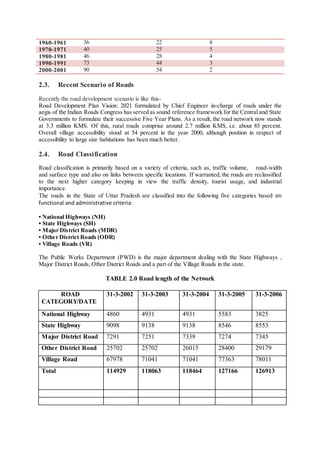
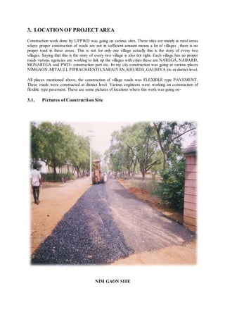
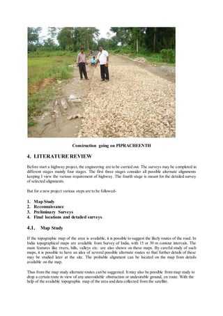


This document provides details about a summer training report on road development and maintenance in rural areas of Uttar Pradesh, India. It discusses the importance of rural connectivity for socio-economic development. The report outlines the methodology used for flexible pavement construction, which includes earthwork, subgrade preparation, wet mix macadam layer construction, and design criteria. The training involved observing construction work at various rural sites, which involved processes like excavation, embankment formation, aggregate spreading, and compaction.


