Downloaded 203 times


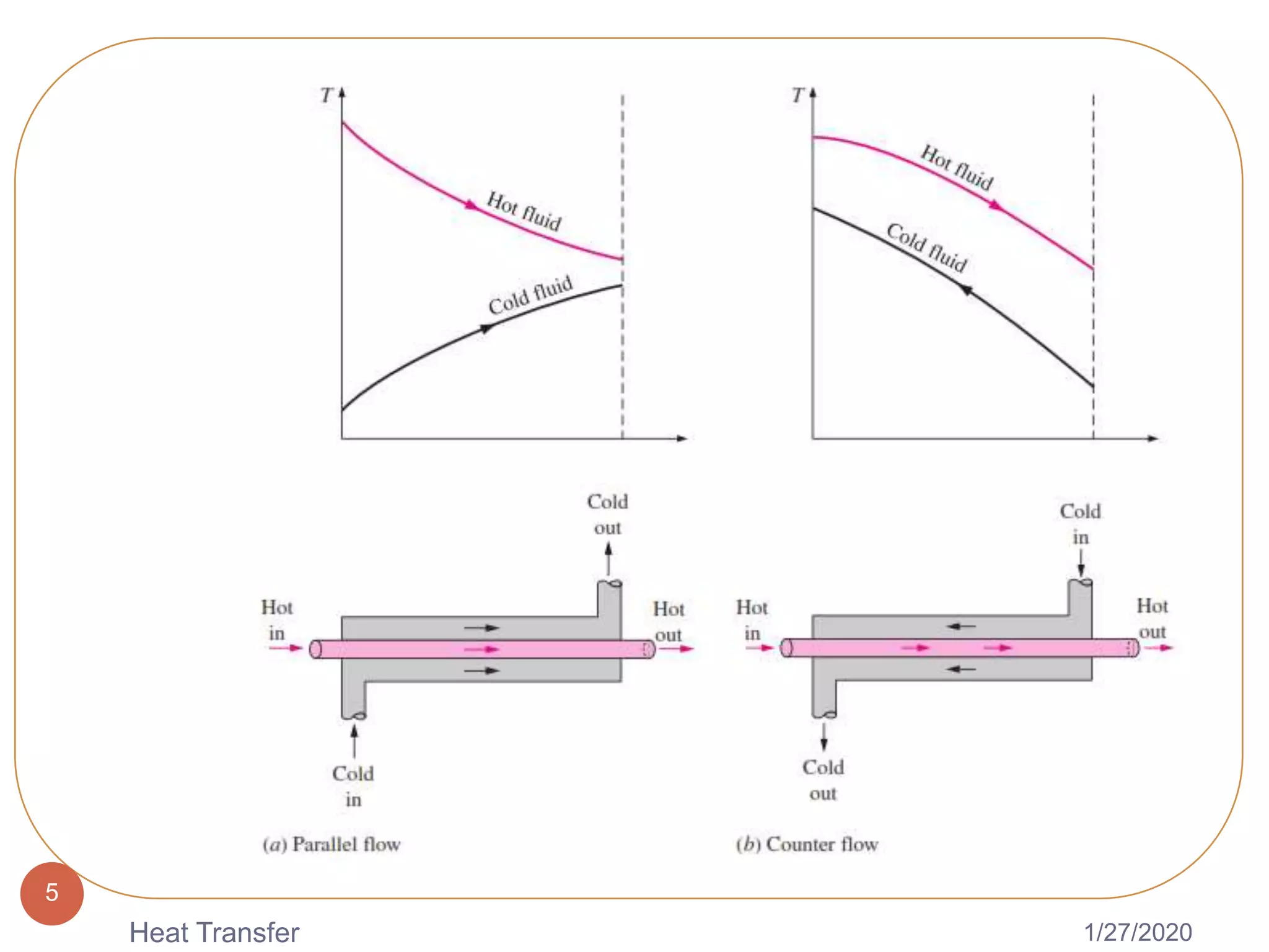


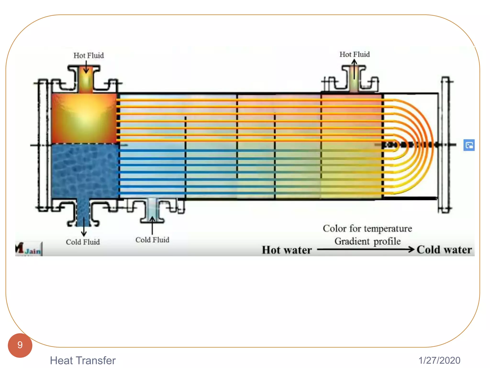


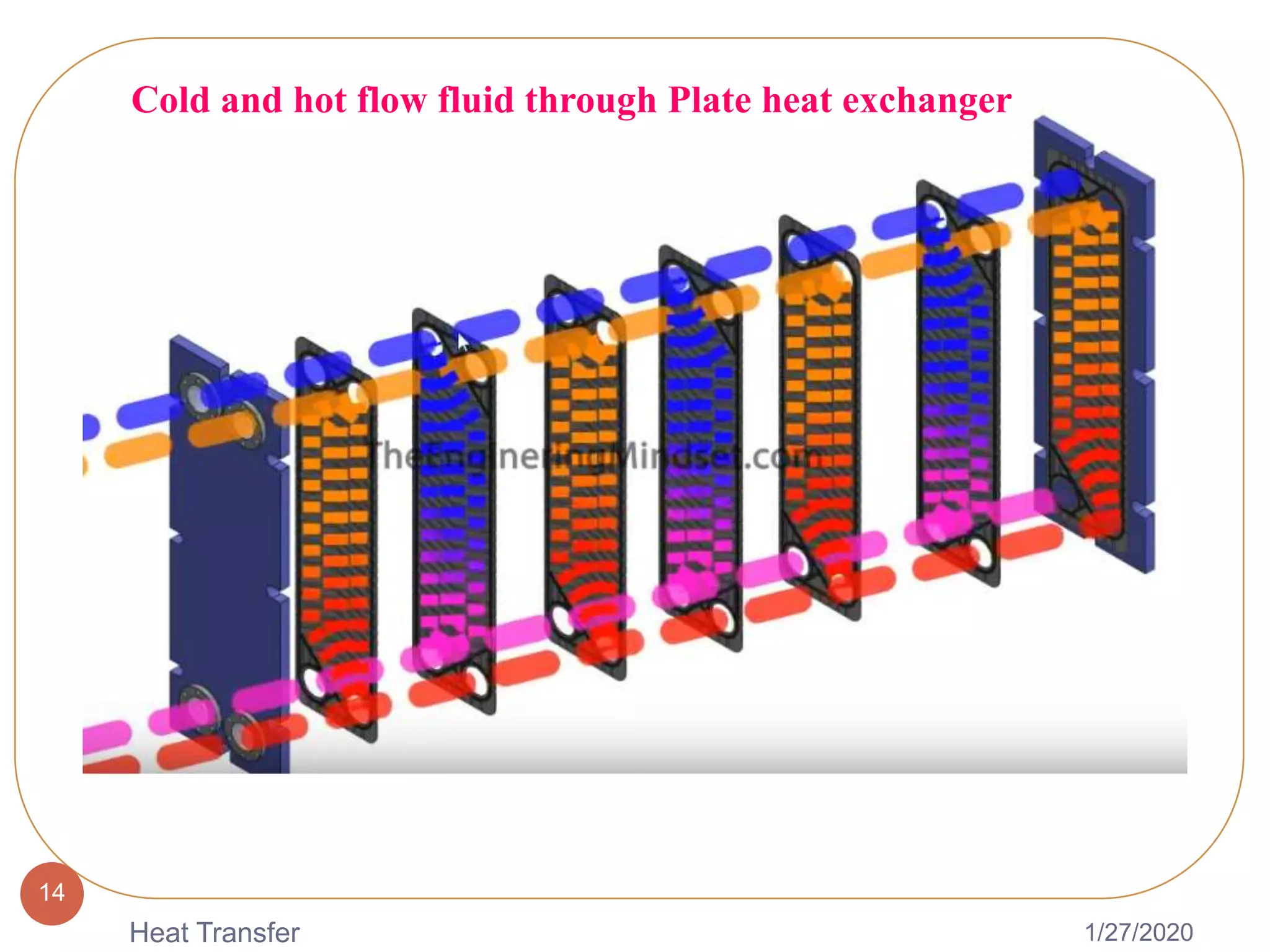
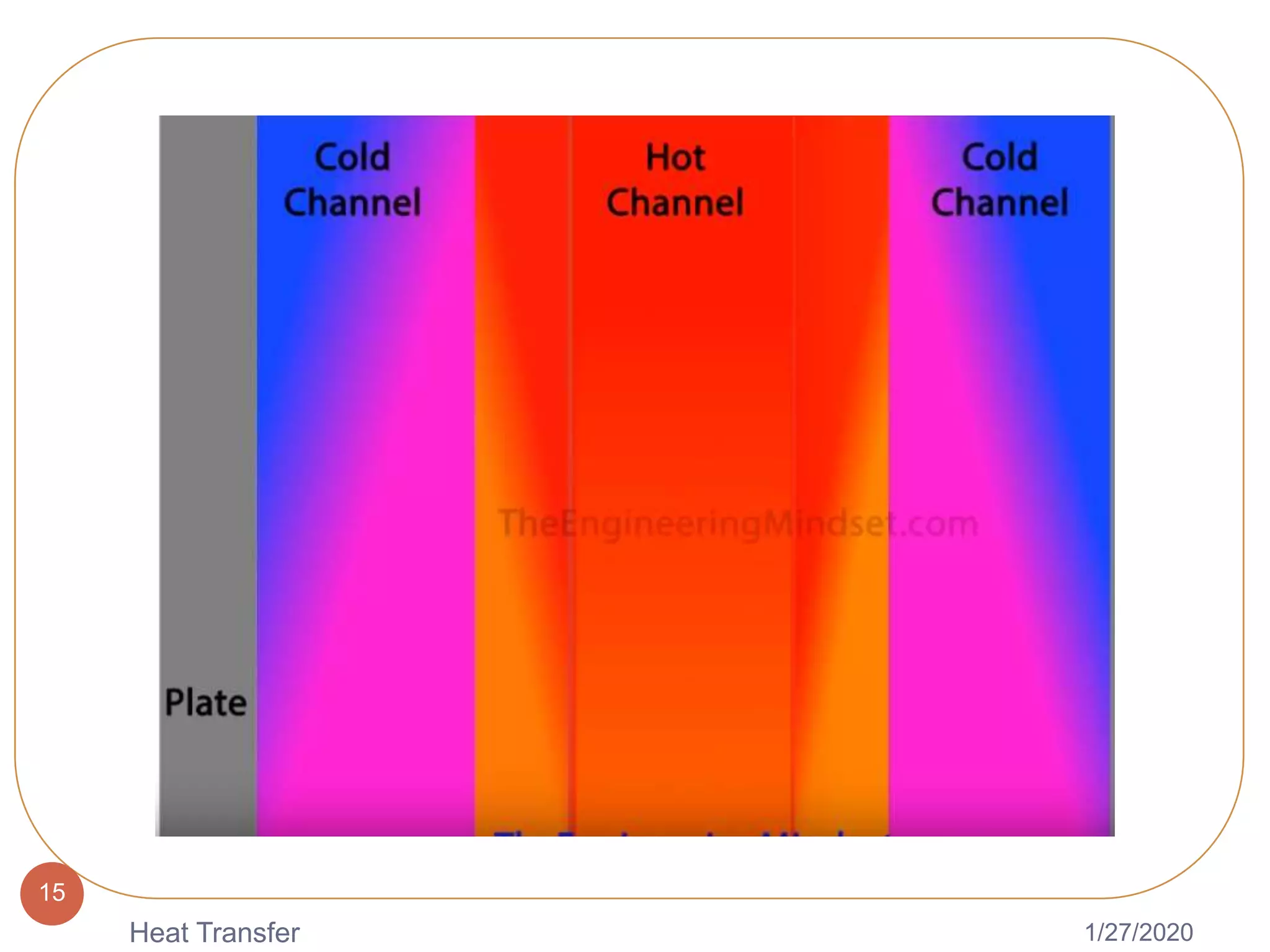
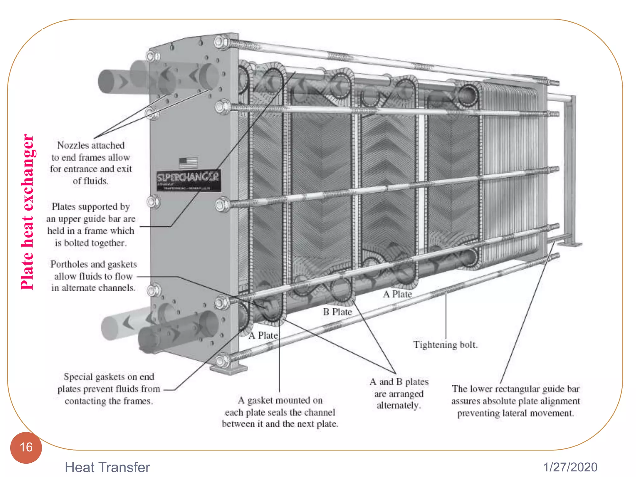
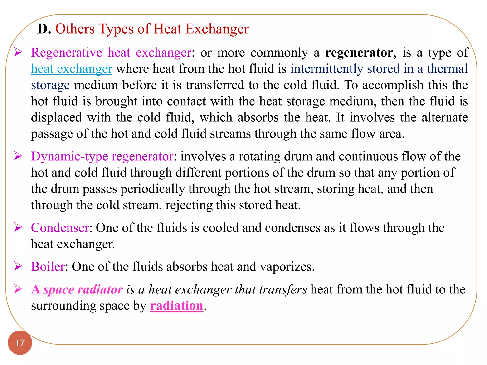
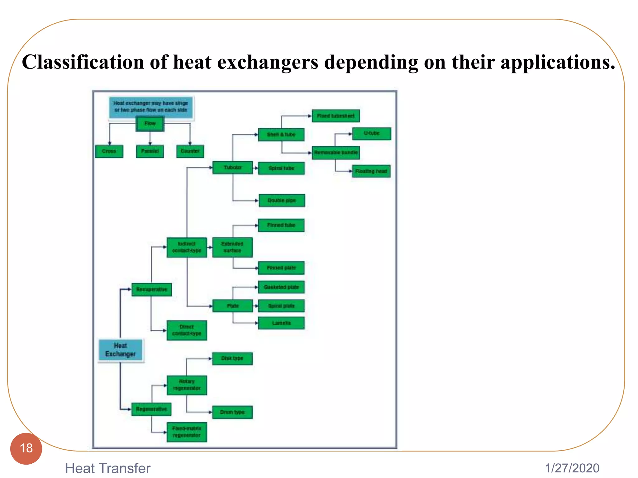


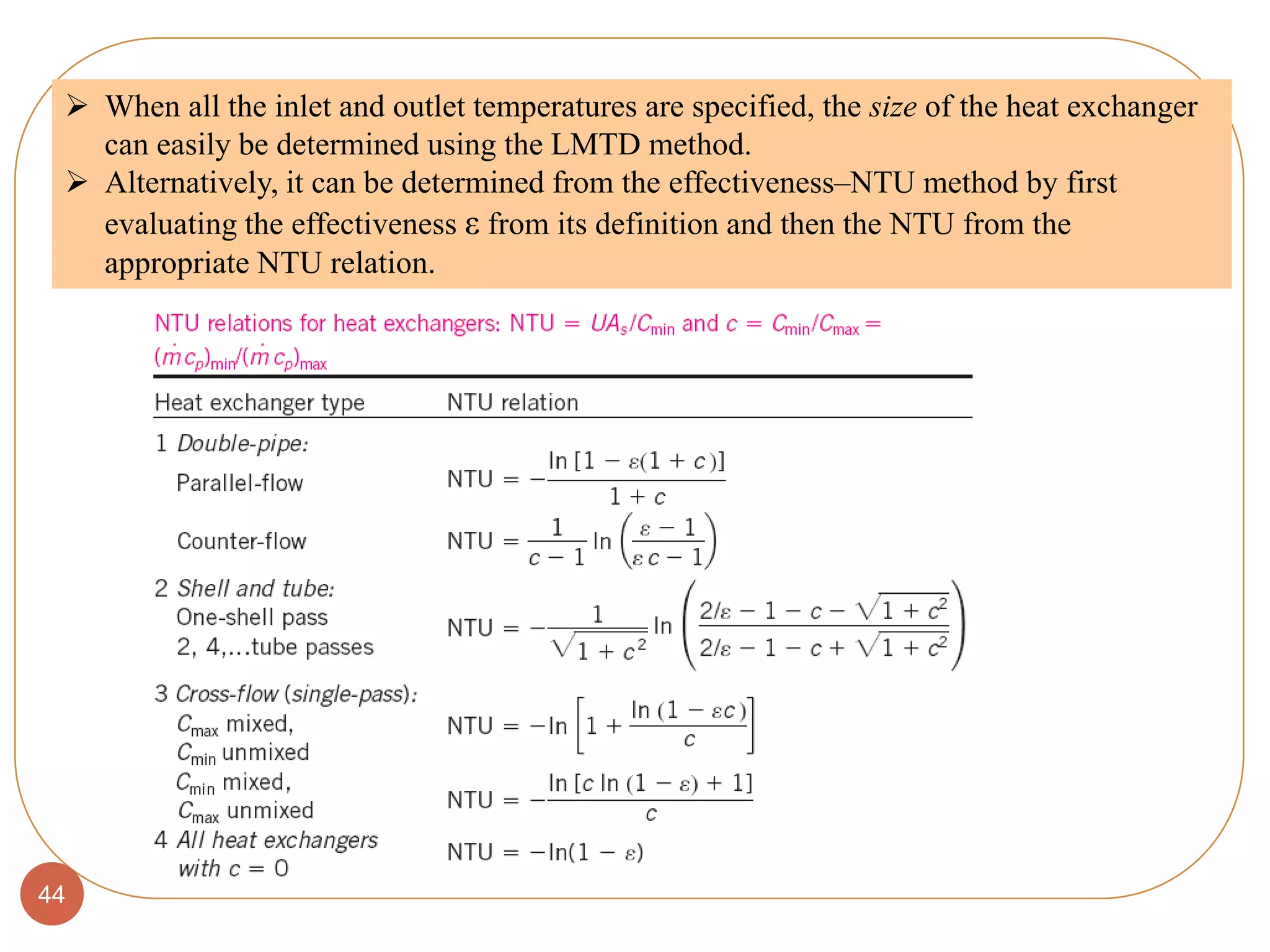
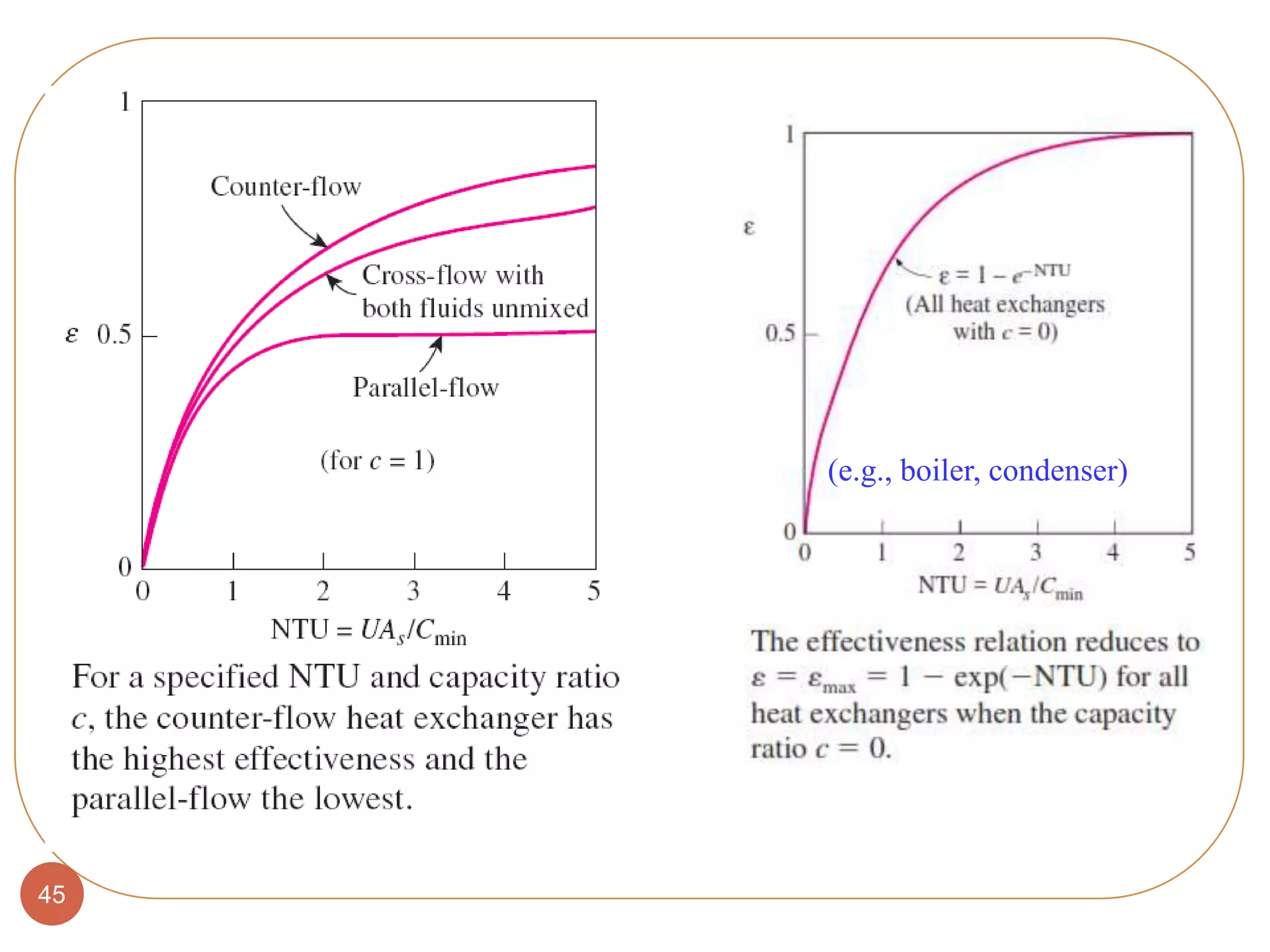

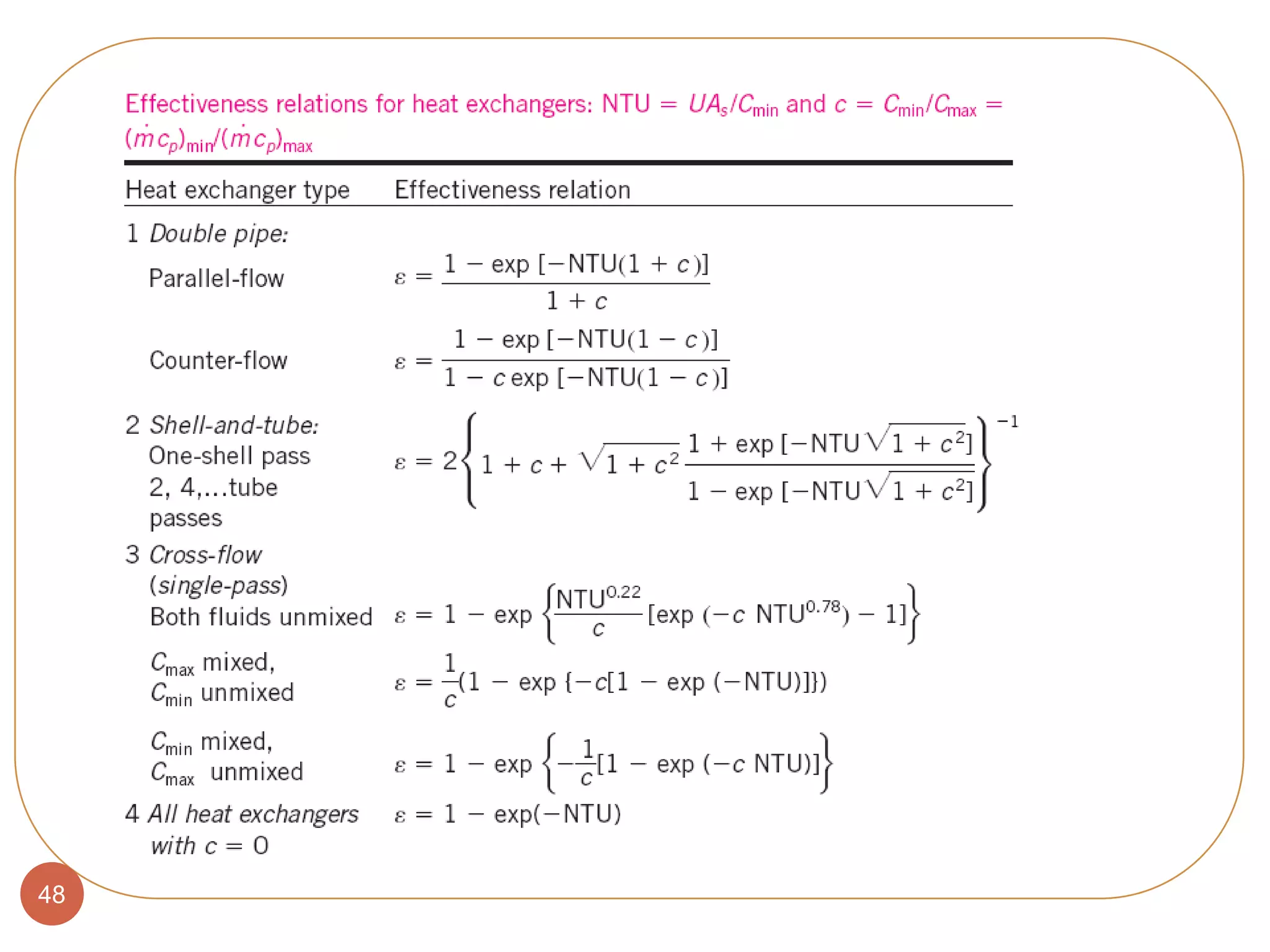


The document provides an overview of heat exchangers, including types, classifications, design considerations, and performance factors such as fouling. It discusses various configurations, such as double-pipe, compact, and plate heat exchangers, along with methodologies for analyzing their effectiveness and heat transfer coefficients. Key focus areas include the logarithmic mean temperature difference method and challenges associated with fouling in heat exchangers, highlighting the complexities involved in thermal energy exchange in engineering applications.