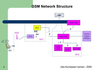
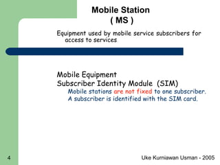
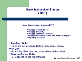
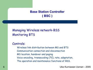
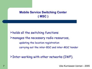
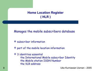
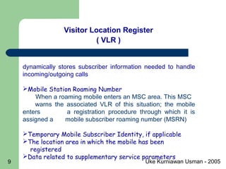
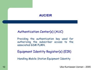
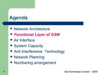
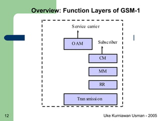
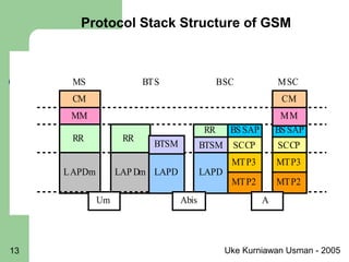
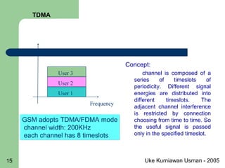
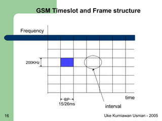
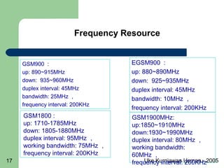
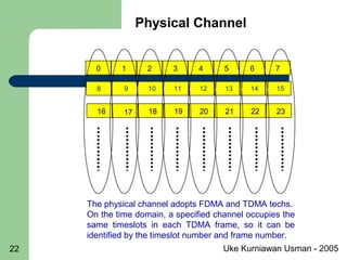
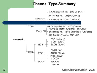
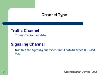
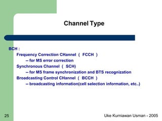
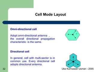
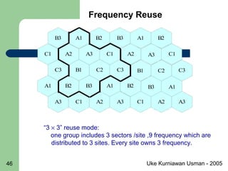
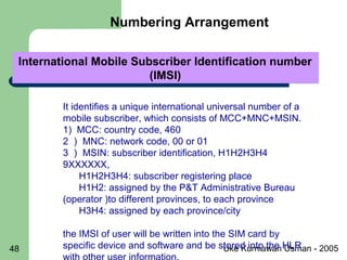
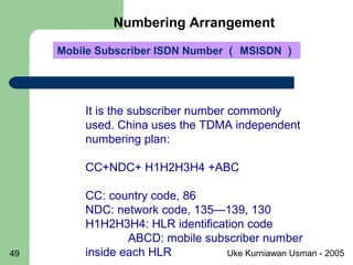
Uke Kurniawan Usman - 20051
GSM Fundamental
By
Uke Kurniawan Usman
Uke Kurniawan Usman - 20052
Agenda
 Network Architecture
 Functional Layer of GSM
 Air Interface
 System Capacity
 Anti Interference Technology
 Network Planning
 Numbering arrangement
Uke Kurniawan Usman - 20053
MSC/VLR
HLR/
AUC EIR SC/VM
OMC
BSC
BTS
PSTN
ISDN
PSPDN
MS
BSS
MSS
Um
Abi
s
BIE
A
F
C
H
MSC/VLR
E
GSM Network Structure
Uke Kurniawan Usman - 20054
Equipment used by mobile service subscribers for
access to services.
Mobile Station
( MS )
Mobile Equipment
Subscriber Identity Module (SIM)
Mobile stations are not fixed to one subscriber.
A subscriber is identified with the SIM card.
Uke Kurniawan Usman - 20055
Base Transceiver Station (BTS)
Wireless transmission
Wireless diversity
Wireless channel encryption
Conversion between wired and wireless signals
Frequency Hopping
BaseBand Unit:
voice and data speed adapting and channel coding
RF Unit:
modulating/demodulating, transmitter and receiver
Common Control Unit:
BTS operation and maintenance
GSM Network Entity
Base Transceiver Station
( BTS )
Uke Kurniawan Usman - 20056
Managing Wireless network-BSS
Monitoring BTS
Controls:
Wireless link distribution between MS and BTS
Communication connection and disconnection
MS location, handover and paging
Voice encoding, transecoding (TC), rate, adaptation,
The operation and maintenance functions of BSS.
Base Station Controller
( BSC )
GSM Network Entity
Uke Kurniawan Usman - 20057
holds all the switching functions
manages the necessary radio resources,
updating the location registration
carrying out the inter-BSC and inter-MSC tender
Inter-working with other networks (IWF).
GSM Network Entity
Mobile Service Switching Center
( MSC )
Uke Kurniawan Usman - 20058
Manages the mobile subscribers database
 subscriber information
 part of the mobile location information
 3 identities essential
the International Mobile subscriber Identity
the Mobile station ISDN Number
the VLR address
GSM Network Entity
Home Location Register
( HLR )
Uke Kurniawan Usman - 20059
Visitor Location Register
( VLR )
dynamically stores subscriber information needed to handle
incoming/outgoing calls
Mobile Station Roaming Number
When a roaming mobile enters an MSC area. This MSC
warns the associated VLR of this situation; the mobile
enters a registration procedure through which it is
assigned a mobile subscriber roaming number (MSRN)
Temporary Mobile Subscriber Identity, if applicable
The location area in which the mobile has been
registered
Data related to supplementary service parameters
GSM Network Entity
Uke Kurniawan Usman - 200510
AUC/EIR
Authentication Center(s) (AUC)
Providing the authentication key used for
authorizing the subscriber access to the
associated GSM PLMN.
Equipment Identity Register(s) (EIR)
Handling Mobile Station Equipment Identity
GSM Network Entity
Uke Kurniawan Usman - 200511
Agenda
 Network Architecture
 Functional Layer of GSM
 Air Interface
 System Capacity
 Anti Interference Technology
 Network Planning
 Numbering arrangement
Uke Kurniawan Usman - 200512
OAM
S ervice carrier
CM
MM
RR
Subscriber
Tran smission
Overview: Function Layers of GSM-1
Uke Kurniawan Usman - 200513
CM
MM
RR
LAPDm
MS
RR
LAP Dm
Um
LAPD
BTSM
LAPD
Abis
RR
BTSM SCCP
MTP3
BS SAP
BTS BSC
MTP2
SCCP
MTP3
BS SAP
MTP2
CM
MM
MSC
A
Protocol Stack Structure of GSM
Uke Kurniawan Usman - 200514
Agenda
Network Architecture
Functional Layer of GSM
Air Interface
System Capacity
Anti Interference Technology
Network Planning
Numbering arrangement
Uke Kurniawan Usman - 200515
Concept:
channel is composed of a
series of timeslots of
periodicity. Different signal
energies are distributed into
different timeslots. The
adjacent channel interference
is restricted by connection
choosing from time to time. So
the useful signal is passed
only in the specified timeslot.
GSM adopts TDMA/FDMA mode
channel width: 200KHz
each channel has 8 timeslots
GSM adopts TDMA/FDMA mode
channel width: 200KHz
each channel has 8 timeslots
User 1
User 2
User 3
Frequency
time
TDMA
Uke Kurniawan Usman - 200516
GSM Timeslot and Frame structure
time
Frequency
BP
15/26ms
200KHz
interval
Uke Kurniawan Usman - 200517
Frequency Resource
GSM900 :
up: 890~915MHz
down: 935~960MHz
duplex interval: 45MHz
bandwidth: 25MHz ,
frequency interval: 200KHz
GSM1800 :
up: 1710-1785MHz
down: 1805-1880MHz
duplex interval: 95MHz ,
working bandwidth: 75MHz ,
frequency interval: 200KHz
EGSM900 :
up: 880~890MHz
down: 925~935MHz
duplex interval: 45MHz
bandwidth: 10MHz ,
frequency interval: 200KHz
GSM1900MHz:
up:1850~1910MHz
down:1930~1990MHz
duplex interval: 80MHz ,
working bandwidth:
60MHz ,
frequency interval: 200KHz
Uke Kurniawan Usman - 200518
1800MHz
1900MHz
900MHzWhich one?
Single Band Network General Priority
High
Low
Reason
For SubscriberFor Operator
Propagation
Characteristic
New Operator
Frequency Resource
Uke Kurniawan Usman - 200519
1800MHz
1900MHz
900MHz
Single Band Network
Single Band
Dual Band
Triple Band
In a sense, the network determines the handsets
can be selected.
But nowadays, most handsets support dual
band.
Frequency Resource
Uke Kurniawan Usman - 200520
Propagation characteristic
Cell coverage radius :
The higher the propagation
frequency
The higher the propagation loss
The smaller the cell coverage radius.
900MHz
1800MHz
1900MHz
Single Band Network
Frequency Resource
We know
Uke Kurniawan Usman - 200521
0 2045 2046 2047321 2044
3210 4947 48 50
0 24 251
1 super high frame = 2048 super frame = 2715648 TDMA frame
1 super frame = 1326 TDMA frame ( 6.12s )
0 1 2524 504910
1 multiplex frame = 26 TDMA frames ( 120ms ) 1 multiplex frame = 51 TDMA frame
0 1 765432
1 TDMA frame = 8 timeslot ( 120/26 = 4.615ms )
BCCH
CCCH
SDCHSACCH/TCH
FACCH
Timeslot and Frame structure
Uke Kurniawan Usman - 200522
0 1 765432
8 9 151413121110
16 17 232221201918
The physical channel adopts FDMA and TDMA techs.
On the time domain, a specified channel occupies the
same timeslots in each TDMA frame, so it can be
identified by the timeslot number and frame number.
Physical Channel
Uke Kurniawan Usman - 200523
channel
TCH
CCH
Voice CH
Data CH
FR Voice Traffic Channel (TCH/FS)
HR Traffic Channel (TCH/HS)
4.8Kbit/s HR TCH (TCH/H4.8)
9.6Kbit/s FR TCH(TCH/F9.6)
4.8Kbit/s FR TCH (TCH/F4.8)
BCH
FCCH (down)
SCH (down)
BCCH (down)
CCCH
RACH (up)
AGCH (down)
PCH (down)
DCCH
SDCCH
FACCH
SACCH
14.4Kbit/s FR TCH (TCH/F14.4)
Enhanced FR Traffic Channel (TCH/EFR)
Channel Type-Summary
Uke Kurniawan Usman - 200524
Channel Type
Traffic Channel
Transmit voice and data
Signaling Channel
transmit the signaling and synchronous data between BTS and
MS.
Uke Kurniawan Usman - 200525
Channel Type
BCH :
Frequency Correction CHannel ( FCCH )
-- for MS error correction
Synchronous Channel ( SCH)
-- for MS frame synchronization and BTS recognization
Broadcasting Control CHannel ( BCCH )
-- broadcasting information(cell selection information, etc..)
Uke Kurniawan Usman - 200526
Channel Type
DCCH
Self-help Dedicated Control Channel ( SDCCH )
for channel distribution information transmission
Slow Associated Control Channel ( SACCH )
combined with one traffic channel or SDCCH, to transmit some
specific information of user information
Fast Associated Control Channel ( FACCH )
combined with one traffic channel, taking the same signal as
SDCCH. It occupies the service channel to transmit signaling
information.
Uke Kurniawan Usman - 200527
Structure of 51-frame Control CH
SF B C
R R R R R R R R R R R R R R R R R R R R R R R R R R R R R R R
51 Frame
SF C C SF C C SF C C I
R R R R R R R R R R
D0 D1 D2 D3 D4 D5 D6 D7 A0 A1 A2 A3
SF C C
R R R R R R R R R R
III
D0 D1 D2 D3 D4 D5 D6 D7 A4 A5 A6 A7 III
A1 A2 A3 III
A5 A6 A7 III
D0 D1 D2 D3 D4 D5 D6 D7 A0
D0 D1 D2 D3 D4 D5 D6 D7 A4
SF B C SF C C SF D0 D1 SF D2 D3 ISF A0 A1
SF B C SF C C SF D0 D1 SF D2 D3 ISF A2 A3
D3
D3
R R
R R
A2 A3
A0 A1
D2
D2
SF
SF
D0 D1
D0 D1
R R R R R R R R R R R R R R R R R R R R R R R
F:FCCH S:SCH
B:BCCH C:CCCH(CCCH=PCH+AGCH+RACH)
R:RACH D:SDCCH
A:SACCH/C I: idle
BCCH+CCCH
(Downlink)
BCCH+CCCH
(uplink)
8 SDCCH/8
(Downlink)
8 SDCCH/8
(uplink)
BCCH+CCCH+
4SDCCH/4
(Downlink)
BCCH+CCCH+
4SDCCH/4
(uplink)
(a) FCCH+SCH+BCCH+CCCH
(b) SDCCH/8(0,...,7)+SACCH/C8(0,...,7)
(c) FCCH+SCH+CCCH+SDCCH/4(0,...,3)+SACCH/C4(0,...,3)
Uke Kurniawan Usman - 200528
Channel Combination Type
Several logic channels combine together in some way to form
some specific types of channel to transmit user data or signaling
information. They are called combined channels. One combined
channel can be mapped to a physical channel.
There are the following combined channels:
a TCH/F + FACCH/F + SACCH/TF
b TCH/H(0,1) + FACCH/H(0,1) + SACCH/TH(0,1)
c TCH/H(0,0) + FACCH/H(0,1) + SACCH/TH(0,1) + TCH/H(1,1)
d FCCH + SCH + BCCH + CCCH
e FCCH + SCH + BCCH + CCCH + SDCCH/4(0...3) + SACCH/C4(0...3)
f BCCH + CCCH
g SDCCH/8(0 ..7) + SACCH/C8(0 .. 7)
CCCH = PCH + RACH + AGCH
Uke Kurniawan Usman - 200529
 Small capacity cell with only 1 TRX
TN0: FCCH+SCH+CCCH+BCCH+SDCCH/4(0,_,3)+SACCH/C4(0,_,3);
TN1-7: TCH/F+FACCH/F+SACCH/TF
 The medium-size cell with 4 TRXs
1TN0 group: FCCH+SCH+BCCH+CCCH;
2 SDCCH/8(0,_,7)+SACCH/C8(0,_,7);
29 TCH/F+FACCH/F+SACCH/TF
Channel Assignment inside cells
Uke Kurniawan Usman - 200530
 Large-size cell with 12 TRXs
1 TN0 group: FCCH+SCH+BCCH+CCCH;
1 TN2 group, 1 TN4 group and 1 TN6 group: BCCH+CCCH;
5 SDCCH/8(0,_,7)+SACCH/C8(0,_,7);
87 TCH/F+FACCH/F+SACCH/TF
Channel Assignment inside cells
Uke Kurniawan Usman - 200531
Agenda
Network Architecture
Functional Layer of GSM
Air Interface
System Capacity
Anti Interference Technology
Network Planning
Numbering arrangement
Uke Kurniawan Usman - 200532
Cell Mode Layout
O
Omni-directional cell
Adopt omni-directional antenna ,
the overall directional propagation
characteristic is the same.
Directional cell
In general, cell with multi-sector is in
common use. Every directional cell
adopts directional antenna.
Uke Kurniawan Usman - 200533
 Capacity
When the traffic is very low, and no possibility for quick
increment, Omni-directional cell is used in common.
Otherwise, we suggest to adopt the sector cell.
Note: TRX-transceiver,each TRX handles 1 frequency.
 Coverage Area
Sector cell is often used to enlarge the cell coverage
radius because of the higher antenna gain.
For special coverage ,such as road coverage, two-sector
cell is adopted firstly.
BTS Mode
Uke Kurniawan Usman - 200534
Erlang :
the traffic intensity of a totally occupied channel (i.e.
the call hour of a unit hour or the call minute of a unit
minute). For example, the traffic of a channel occupied
for 30 minutes in an hour is 0.5 Erlang)
GOS:
defined as the probability of call blocking or the
probability when the call delay time is longer than a
given queuing time.
System capacity
Uke Kurniawan Usman - 200535
Agenda
Network Architecture
Functional Layer of GSM
Air Interface
System Capacity
Anti Interference Technology
Network Planning
Numbering arrangement
Uke Kurniawan Usman - 200536
Reasons for Interference
The transmission path is very complex, ranging
from the simple line-of-sight transmission to
encountering such terrain as buildings, hills and
trees. Wireless channels are extremely
unpredictable.
Abrupt drop, or fading, of signal strength in the
land mobile wireless channel is quite common. The
fading feature of the mobile channel depends on the
radio wave propagation environment.
Uke Kurniawan Usman - 200537
Reasons for interference
Environmental factors:
• Terrain (mountains, hills, plains, water bodies, etc.);
• The quantity, heights, distribution and materials of
buildings;
• The vegetation of the region;
• Weather conditions;
• Natural and artificial electromagnetic noises;
• Frequency;
• How MS is moved.
Uke Kurniawan Usman - 200538
Co-Channel Interference
Conception:
the interference among the signals of co-
channel cells is called co-channel interference.
Result from :
Frequency reuse
Reduction method:
co-channel cells must physically be
spaced at a minimum interval to ensure
adequate isolation of transmissions. 
Interference
Uke Kurniawan Usman - 200539
 Adjacent Channel Interference
Conception:
The signal interference from the frequency
adjacent to that of the signal used is called
adjacent channel interference.
Reduction method:
accurate filtering and channel allocation
(maximizing channel intervals of the
cell). Interval of frequency reuse inter-cell
interference, such as C/I, C/A
Interference
Uke Kurniawan Usman - 200540
 FH technology
 Dynamic power control (DPC)
 Discontinuous Transceiving
(DTX)
 Diversity receiving technique
Solution -Anti-interference
Uke Kurniawan Usman - 200541
Reason:
 counteract Rayleigh Fading
 scatter interference among multiple calls
Types:
 Base band frequency hopping
keeps the transmission and receiving frequency of each
carrier unit unchanged, but merely sends FU transmission
data to different carrier units at different FN moments.
 radio frequency hopping
controls the frequency synthesizer of each transceiver,
making it hop according to different schemes in different time
slots.
Frequency Hopping Technique
Uke Kurniawan Usman - 200542
Discontinuous Speech Transmission (DTX)
TRAU BTS
BTS MS
Speech frame
480 ms
comfort noise frame
Two aims can be achieved by adopting DTX mode:
•lower the total interference electric level in the air
•save transmitter power.
Uke Kurniawan Usman - 200543
The multi-path propagation of radio signals causes
magnitude fading and delay time.
 Space Diversity (antenna diversity)
 Polarization Diversity
orthogonal polarization diversity.
horizontal polarization and vertical polarization.
 Frequency Diversity
The working principle of this technology is that
such fading won’t take place on the frequency
outside the coherence bandwidth of the channel.
Diversity Reception Technology
Uke Kurniawan Usman - 200544
Agenda
Network Architecture
Functional Layer of GSM
Air Interface
System Capacity
Anti Interference Technology
Network Planning
Numbering arrangement
Uke Kurniawan Usman - 200545
“4 × 3” reuse mode:
one group includes 3 sectors /site ,12 frequency which
are distributed to 4 sites. Every site owns 3 frequency.
Frequency Reuse
A3
D2B1
C3
B2D1
D3
A2C1
B3
C2A1
B3
C2A1
A3
A1B1
D1
D3D2
C3
B2A1
C3D2
C3
C1
D2B1C2A1
A2C1
D3
Uke Kurniawan Usman - 200546
A3
C2B1
B3
A2C1
C3
B2A1
A3
C2B1
B3
A2C1
B3
A1C1
A1
A3A2
C3
B2A1
A3A3
C3
C1
B2A1B2A1
A2C1
B3
Frequency Reuse
“3 × 3” reuse mode:
one group includes 3 sectors /site ,9 frequency which are
distributed to 3 sites. Every site owns 3 frequency.
Uke Kurniawan Usman - 200547
Agenda
Network Architecture
Functional Layer of GSM
Air Interface
System Capacity
Anti Interference Technology
Network Planning
Numbering arrangement
Uke Kurniawan Usman - 200548
Numbering Arrangement
International Mobile Subscriber Identification number
(IMSI)
International Mobile Subscriber Identification number
(IMSI)
It identifies a unique international universal number of a
mobile subscriber, which consists of MCC+MNC+MSIN.
1) MCC: country code, 460
2 ) MNC: network code, 00 or 01
3 ) MSIN: subscriber identification, H1H2H3H4
9XXXXXX,
H1H2H3H4: subscriber registering place
H1H2: assigned by the P&T Administrative Bureau
(operator )to different provinces, to each province
H3H4: assigned by each province/city
the IMSI of user will be written into the SIM card by
specific device and software and be stored into the HLR
Uke Kurniawan Usman - 200549
It is the subscriber number commonly
used. China uses the TDMA independent
numbering plan:
CC+NDC+ H1H2H3H4 +ABC
CC: country code, 86
NDC: network code, 135—139, 130
H1H2H3H4: HLR identification code
ABCD: mobile subscriber number
inside each HLR
Mobile Subscriber ISDN Number ( MSISDN )Mobile Subscriber ISDN Number ( MSISDN )
Numbering Arrangement
Uke Kurniawan Usman - 200550
International Mobile Equipment Identification code
(IMEI)
International Mobile Equipment Identification code
(IMEI)
It will uniquely identify a mobile station. It is a
decimal number of 15 digits. Its structure is:
TAC+FAC+SNR+SP
TAC=model ratification code, 6 digits
FAC=factory assembling code, 2 digits
SNR=sequence code, 6 digits
SP=reserved, 1 digit
Numbering Arrangement
Uke Kurniawan Usman - 200551
Mobile Subscriber Roaming Number
(MSRN)
Mobile Subscriber Roaming Number
(MSRN)
The MSRN is temporarily distributed to the
subscriber by the VLR according to the request
by the HLR when this subscriber is called. The
MSRN is released and can be assigned to other
subscriber later.
   CC + NDC + 00 + M1M2M3 + ABC
   CC: country code, 86
    NDC: mobile network code, 135—139,
130
   M1M2: same as the H2H3 of MSISDN
   ABC: 000 -- 999
Numbering Arrangement
Uke Kurniawan Usman - 200552
Temporarily Mobile Subscriber Identification Number
(TMSI)
Temporarily Mobile Subscriber Identification Number
(TMSI)
To insure the IMSI security, the VLR will
assign an unique TMSI number for the
accessed subscriber. It is used locally only
and is a 4-byte TMSI number BCD code.
Numbering Arrangement

Gsm fundamental-uku

  • 1.
    Uke Kurniawan Usman- 20051 GSM Fundamental By Uke Kurniawan Usman
  • 2.
    Uke Kurniawan Usman- 20052 Agenda  Network Architecture  Functional Layer of GSM  Air Interface  System Capacity  Anti Interference Technology  Network Planning  Numbering arrangement
  • 3.
    Uke Kurniawan Usman- 20053 MSC/VLR HLR/ AUC EIR SC/VM OMC BSC BTS PSTN ISDN PSPDN MS BSS MSS Um Abi s BIE A F C H MSC/VLR E GSM Network Structure
  • 4.
    Uke Kurniawan Usman- 20054 Equipment used by mobile service subscribers for access to services. Mobile Station ( MS ) Mobile Equipment Subscriber Identity Module (SIM) Mobile stations are not fixed to one subscriber. A subscriber is identified with the SIM card.
  • 5.
    Uke Kurniawan Usman- 20055 Base Transceiver Station (BTS) Wireless transmission Wireless diversity Wireless channel encryption Conversion between wired and wireless signals Frequency Hopping BaseBand Unit: voice and data speed adapting and channel coding RF Unit: modulating/demodulating, transmitter and receiver Common Control Unit: BTS operation and maintenance GSM Network Entity Base Transceiver Station ( BTS )
  • 6.
    Uke Kurniawan Usman- 20056 Managing Wireless network-BSS Monitoring BTS Controls: Wireless link distribution between MS and BTS Communication connection and disconnection MS location, handover and paging Voice encoding, transecoding (TC), rate, adaptation, The operation and maintenance functions of BSS. Base Station Controller ( BSC ) GSM Network Entity
  • 7.
    Uke Kurniawan Usman- 20057 holds all the switching functions manages the necessary radio resources, updating the location registration carrying out the inter-BSC and inter-MSC tender Inter-working with other networks (IWF). GSM Network Entity Mobile Service Switching Center ( MSC )
  • 8.
    Uke Kurniawan Usman- 20058 Manages the mobile subscribers database  subscriber information  part of the mobile location information  3 identities essential the International Mobile subscriber Identity the Mobile station ISDN Number the VLR address GSM Network Entity Home Location Register ( HLR )
  • 9.
    Uke Kurniawan Usman- 20059 Visitor Location Register ( VLR ) dynamically stores subscriber information needed to handle incoming/outgoing calls Mobile Station Roaming Number When a roaming mobile enters an MSC area. This MSC warns the associated VLR of this situation; the mobile enters a registration procedure through which it is assigned a mobile subscriber roaming number (MSRN) Temporary Mobile Subscriber Identity, if applicable The location area in which the mobile has been registered Data related to supplementary service parameters GSM Network Entity
  • 10.
    Uke Kurniawan Usman- 200510 AUC/EIR Authentication Center(s) (AUC) Providing the authentication key used for authorizing the subscriber access to the associated GSM PLMN. Equipment Identity Register(s) (EIR) Handling Mobile Station Equipment Identity GSM Network Entity
  • 11.
    Uke Kurniawan Usman- 200511 Agenda  Network Architecture  Functional Layer of GSM  Air Interface  System Capacity  Anti Interference Technology  Network Planning  Numbering arrangement
  • 12.
    Uke Kurniawan Usman- 200512 OAM S ervice carrier CM MM RR Subscriber Tran smission Overview: Function Layers of GSM-1
  • 13.
    Uke Kurniawan Usman- 200513 CM MM RR LAPDm MS RR LAP Dm Um LAPD BTSM LAPD Abis RR BTSM SCCP MTP3 BS SAP BTS BSC MTP2 SCCP MTP3 BS SAP MTP2 CM MM MSC A Protocol Stack Structure of GSM
  • 14.
    Uke Kurniawan Usman- 200514 Agenda Network Architecture Functional Layer of GSM Air Interface System Capacity Anti Interference Technology Network Planning Numbering arrangement
  • 15.
    Uke Kurniawan Usman- 200515 Concept: channel is composed of a series of timeslots of periodicity. Different signal energies are distributed into different timeslots. The adjacent channel interference is restricted by connection choosing from time to time. So the useful signal is passed only in the specified timeslot. GSM adopts TDMA/FDMA mode channel width: 200KHz each channel has 8 timeslots GSM adopts TDMA/FDMA mode channel width: 200KHz each channel has 8 timeslots User 1 User 2 User 3 Frequency time TDMA
  • 16.
    Uke Kurniawan Usman- 200516 GSM Timeslot and Frame structure time Frequency BP 15/26ms 200KHz interval
  • 17.
    Uke Kurniawan Usman- 200517 Frequency Resource GSM900 : up: 890~915MHz down: 935~960MHz duplex interval: 45MHz bandwidth: 25MHz , frequency interval: 200KHz GSM1800 : up: 1710-1785MHz down: 1805-1880MHz duplex interval: 95MHz , working bandwidth: 75MHz , frequency interval: 200KHz EGSM900 : up: 880~890MHz down: 925~935MHz duplex interval: 45MHz bandwidth: 10MHz , frequency interval: 200KHz GSM1900MHz: up:1850~1910MHz down:1930~1990MHz duplex interval: 80MHz , working bandwidth: 60MHz , frequency interval: 200KHz
  • 18.
    Uke Kurniawan Usman- 200518 1800MHz 1900MHz 900MHzWhich one? Single Band Network General Priority High Low Reason For SubscriberFor Operator Propagation Characteristic New Operator Frequency Resource
  • 19.
    Uke Kurniawan Usman- 200519 1800MHz 1900MHz 900MHz Single Band Network Single Band Dual Band Triple Band In a sense, the network determines the handsets can be selected. But nowadays, most handsets support dual band. Frequency Resource
  • 20.
    Uke Kurniawan Usman- 200520 Propagation characteristic Cell coverage radius : The higher the propagation frequency The higher the propagation loss The smaller the cell coverage radius. 900MHz 1800MHz 1900MHz Single Band Network Frequency Resource We know
  • 21.
    Uke Kurniawan Usman- 200521 0 2045 2046 2047321 2044 3210 4947 48 50 0 24 251 1 super high frame = 2048 super frame = 2715648 TDMA frame 1 super frame = 1326 TDMA frame ( 6.12s ) 0 1 2524 504910 1 multiplex frame = 26 TDMA frames ( 120ms ) 1 multiplex frame = 51 TDMA frame 0 1 765432 1 TDMA frame = 8 timeslot ( 120/26 = 4.615ms ) BCCH CCCH SDCHSACCH/TCH FACCH Timeslot and Frame structure
  • 22.
    Uke Kurniawan Usman- 200522 0 1 765432 8 9 151413121110 16 17 232221201918 The physical channel adopts FDMA and TDMA techs. On the time domain, a specified channel occupies the same timeslots in each TDMA frame, so it can be identified by the timeslot number and frame number. Physical Channel
  • 23.
    Uke Kurniawan Usman- 200523 channel TCH CCH Voice CH Data CH FR Voice Traffic Channel (TCH/FS) HR Traffic Channel (TCH/HS) 4.8Kbit/s HR TCH (TCH/H4.8) 9.6Kbit/s FR TCH(TCH/F9.6) 4.8Kbit/s FR TCH (TCH/F4.8) BCH FCCH (down) SCH (down) BCCH (down) CCCH RACH (up) AGCH (down) PCH (down) DCCH SDCCH FACCH SACCH 14.4Kbit/s FR TCH (TCH/F14.4) Enhanced FR Traffic Channel (TCH/EFR) Channel Type-Summary
  • 24.
    Uke Kurniawan Usman- 200524 Channel Type Traffic Channel Transmit voice and data Signaling Channel transmit the signaling and synchronous data between BTS and MS.
  • 25.
    Uke Kurniawan Usman- 200525 Channel Type BCH : Frequency Correction CHannel ( FCCH ) -- for MS error correction Synchronous Channel ( SCH) -- for MS frame synchronization and BTS recognization Broadcasting Control CHannel ( BCCH ) -- broadcasting information(cell selection information, etc..)
  • 26.
    Uke Kurniawan Usman- 200526 Channel Type DCCH Self-help Dedicated Control Channel ( SDCCH ) for channel distribution information transmission Slow Associated Control Channel ( SACCH ) combined with one traffic channel or SDCCH, to transmit some specific information of user information Fast Associated Control Channel ( FACCH ) combined with one traffic channel, taking the same signal as SDCCH. It occupies the service channel to transmit signaling information.
  • 27.
    Uke Kurniawan Usman- 200527 Structure of 51-frame Control CH SF B C R R R R R R R R R R R R R R R R R R R R R R R R R R R R R R R 51 Frame SF C C SF C C SF C C I R R R R R R R R R R D0 D1 D2 D3 D4 D5 D6 D7 A0 A1 A2 A3 SF C C R R R R R R R R R R III D0 D1 D2 D3 D4 D5 D6 D7 A4 A5 A6 A7 III A1 A2 A3 III A5 A6 A7 III D0 D1 D2 D3 D4 D5 D6 D7 A0 D0 D1 D2 D3 D4 D5 D6 D7 A4 SF B C SF C C SF D0 D1 SF D2 D3 ISF A0 A1 SF B C SF C C SF D0 D1 SF D2 D3 ISF A2 A3 D3 D3 R R R R A2 A3 A0 A1 D2 D2 SF SF D0 D1 D0 D1 R R R R R R R R R R R R R R R R R R R R R R R R R R R R R R R R R R R R R R R R R R R R R R F:FCCH S:SCH B:BCCH C:CCCH(CCCH=PCH+AGCH+RACH) R:RACH D:SDCCH A:SACCH/C I: idle BCCH+CCCH (Downlink) BCCH+CCCH (uplink) 8 SDCCH/8 (Downlink) 8 SDCCH/8 (uplink) BCCH+CCCH+ 4SDCCH/4 (Downlink) BCCH+CCCH+ 4SDCCH/4 (uplink) (a) FCCH+SCH+BCCH+CCCH (b) SDCCH/8(0,...,7)+SACCH/C8(0,...,7) (c) FCCH+SCH+CCCH+SDCCH/4(0,...,3)+SACCH/C4(0,...,3)
  • 28.
    Uke Kurniawan Usman- 200528 Channel Combination Type Several logic channels combine together in some way to form some specific types of channel to transmit user data or signaling information. They are called combined channels. One combined channel can be mapped to a physical channel. There are the following combined channels: a TCH/F + FACCH/F + SACCH/TF b TCH/H(0,1) + FACCH/H(0,1) + SACCH/TH(0,1) c TCH/H(0,0) + FACCH/H(0,1) + SACCH/TH(0,1) + TCH/H(1,1) d FCCH + SCH + BCCH + CCCH e FCCH + SCH + BCCH + CCCH + SDCCH/4(0...3) + SACCH/C4(0...3) f BCCH + CCCH g SDCCH/8(0 ..7) + SACCH/C8(0 .. 7) CCCH = PCH + RACH + AGCH
  • 29.
    Uke Kurniawan Usman- 200529  Small capacity cell with only 1 TRX TN0: FCCH+SCH+CCCH+BCCH+SDCCH/4(0,_,3)+SACCH/C4(0,_,3); TN1-7: TCH/F+FACCH/F+SACCH/TF  The medium-size cell with 4 TRXs 1TN0 group: FCCH+SCH+BCCH+CCCH; 2 SDCCH/8(0,_,7)+SACCH/C8(0,_,7); 29 TCH/F+FACCH/F+SACCH/TF Channel Assignment inside cells
  • 30.
    Uke Kurniawan Usman- 200530  Large-size cell with 12 TRXs 1 TN0 group: FCCH+SCH+BCCH+CCCH; 1 TN2 group, 1 TN4 group and 1 TN6 group: BCCH+CCCH; 5 SDCCH/8(0,_,7)+SACCH/C8(0,_,7); 87 TCH/F+FACCH/F+SACCH/TF Channel Assignment inside cells
  • 31.
    Uke Kurniawan Usman- 200531 Agenda Network Architecture Functional Layer of GSM Air Interface System Capacity Anti Interference Technology Network Planning Numbering arrangement
  • 32.
    Uke Kurniawan Usman- 200532 Cell Mode Layout O Omni-directional cell Adopt omni-directional antenna , the overall directional propagation characteristic is the same. Directional cell In general, cell with multi-sector is in common use. Every directional cell adopts directional antenna.
  • 33.
    Uke Kurniawan Usman- 200533  Capacity When the traffic is very low, and no possibility for quick increment, Omni-directional cell is used in common. Otherwise, we suggest to adopt the sector cell. Note: TRX-transceiver,each TRX handles 1 frequency.  Coverage Area Sector cell is often used to enlarge the cell coverage radius because of the higher antenna gain. For special coverage ,such as road coverage, two-sector cell is adopted firstly. BTS Mode
  • 34.
    Uke Kurniawan Usman- 200534 Erlang : the traffic intensity of a totally occupied channel (i.e. the call hour of a unit hour or the call minute of a unit minute). For example, the traffic of a channel occupied for 30 minutes in an hour is 0.5 Erlang) GOS: defined as the probability of call blocking or the probability when the call delay time is longer than a given queuing time. System capacity
  • 35.
    Uke Kurniawan Usman- 200535 Agenda Network Architecture Functional Layer of GSM Air Interface System Capacity Anti Interference Technology Network Planning Numbering arrangement
  • 36.
    Uke Kurniawan Usman- 200536 Reasons for Interference The transmission path is very complex, ranging from the simple line-of-sight transmission to encountering such terrain as buildings, hills and trees. Wireless channels are extremely unpredictable. Abrupt drop, or fading, of signal strength in the land mobile wireless channel is quite common. The fading feature of the mobile channel depends on the radio wave propagation environment.
  • 37.
    Uke Kurniawan Usman- 200537 Reasons for interference Environmental factors: • Terrain (mountains, hills, plains, water bodies, etc.); • The quantity, heights, distribution and materials of buildings; • The vegetation of the region; • Weather conditions; • Natural and artificial electromagnetic noises; • Frequency; • How MS is moved.
  • 38.
    Uke Kurniawan Usman- 200538 Co-Channel Interference Conception: the interference among the signals of co- channel cells is called co-channel interference. Result from : Frequency reuse Reduction method: co-channel cells must physically be spaced at a minimum interval to ensure adequate isolation of transmissions.  Interference
  • 39.
    Uke Kurniawan Usman- 200539  Adjacent Channel Interference Conception: The signal interference from the frequency adjacent to that of the signal used is called adjacent channel interference. Reduction method: accurate filtering and channel allocation (maximizing channel intervals of the cell). Interval of frequency reuse inter-cell interference, such as C/I, C/A Interference
  • 40.
    Uke Kurniawan Usman- 200540  FH technology  Dynamic power control (DPC)  Discontinuous Transceiving (DTX)  Diversity receiving technique Solution -Anti-interference
  • 41.
    Uke Kurniawan Usman- 200541 Reason:  counteract Rayleigh Fading  scatter interference among multiple calls Types:  Base band frequency hopping keeps the transmission and receiving frequency of each carrier unit unchanged, but merely sends FU transmission data to different carrier units at different FN moments.  radio frequency hopping controls the frequency synthesizer of each transceiver, making it hop according to different schemes in different time slots. Frequency Hopping Technique
  • 42.
    Uke Kurniawan Usman- 200542 Discontinuous Speech Transmission (DTX) TRAU BTS BTS MS Speech frame 480 ms comfort noise frame Two aims can be achieved by adopting DTX mode: •lower the total interference electric level in the air •save transmitter power.
  • 43.
    Uke Kurniawan Usman- 200543 The multi-path propagation of radio signals causes magnitude fading and delay time.  Space Diversity (antenna diversity)  Polarization Diversity orthogonal polarization diversity. horizontal polarization and vertical polarization.  Frequency Diversity The working principle of this technology is that such fading won’t take place on the frequency outside the coherence bandwidth of the channel. Diversity Reception Technology
  • 44.
    Uke Kurniawan Usman- 200544 Agenda Network Architecture Functional Layer of GSM Air Interface System Capacity Anti Interference Technology Network Planning Numbering arrangement
  • 45.
    Uke Kurniawan Usman- 200545 “4 × 3” reuse mode: one group includes 3 sectors /site ,12 frequency which are distributed to 4 sites. Every site owns 3 frequency. Frequency Reuse A3 D2B1 C3 B2D1 D3 A2C1 B3 C2A1 B3 C2A1 A3 A1B1 D1 D3D2 C3 B2A1 C3D2 C3 C1 D2B1C2A1 A2C1 D3
  • 46.
    Uke Kurniawan Usman- 200546 A3 C2B1 B3 A2C1 C3 B2A1 A3 C2B1 B3 A2C1 B3 A1C1 A1 A3A2 C3 B2A1 A3A3 C3 C1 B2A1B2A1 A2C1 B3 Frequency Reuse “3 × 3” reuse mode: one group includes 3 sectors /site ,9 frequency which are distributed to 3 sites. Every site owns 3 frequency.
  • 47.
    Uke Kurniawan Usman- 200547 Agenda Network Architecture Functional Layer of GSM Air Interface System Capacity Anti Interference Technology Network Planning Numbering arrangement
  • 48.
    Uke Kurniawan Usman- 200548 Numbering Arrangement International Mobile Subscriber Identification number (IMSI) International Mobile Subscriber Identification number (IMSI) It identifies a unique international universal number of a mobile subscriber, which consists of MCC+MNC+MSIN. 1) MCC: country code, 460 2 ) MNC: network code, 00 or 01 3 ) MSIN: subscriber identification, H1H2H3H4 9XXXXXX, H1H2H3H4: subscriber registering place H1H2: assigned by the P&T Administrative Bureau (operator )to different provinces, to each province H3H4: assigned by each province/city the IMSI of user will be written into the SIM card by specific device and software and be stored into the HLR
  • 49.
    Uke Kurniawan Usman- 200549 It is the subscriber number commonly used. China uses the TDMA independent numbering plan: CC+NDC+ H1H2H3H4 +ABC CC: country code, 86 NDC: network code, 135—139, 130 H1H2H3H4: HLR identification code ABCD: mobile subscriber number inside each HLR Mobile Subscriber ISDN Number ( MSISDN )Mobile Subscriber ISDN Number ( MSISDN ) Numbering Arrangement
  • 50.
    Uke Kurniawan Usman- 200550 International Mobile Equipment Identification code (IMEI) International Mobile Equipment Identification code (IMEI) It will uniquely identify a mobile station. It is a decimal number of 15 digits. Its structure is: TAC+FAC+SNR+SP TAC=model ratification code, 6 digits FAC=factory assembling code, 2 digits SNR=sequence code, 6 digits SP=reserved, 1 digit Numbering Arrangement
  • 51.
    Uke Kurniawan Usman- 200551 Mobile Subscriber Roaming Number (MSRN) Mobile Subscriber Roaming Number (MSRN) The MSRN is temporarily distributed to the subscriber by the VLR according to the request by the HLR when this subscriber is called. The MSRN is released and can be assigned to other subscriber later.    CC + NDC + 00 + M1M2M3 + ABC    CC: country code, 86     NDC: mobile network code, 135—139, 130    M1M2: same as the H2H3 of MSISDN    ABC: 000 -- 999 Numbering Arrangement
  • 52.
    Uke Kurniawan Usman- 200552 Temporarily Mobile Subscriber Identification Number (TMSI) Temporarily Mobile Subscriber Identification Number (TMSI) To insure the IMSI security, the VLR will assign an unique TMSI number for the accessed subscriber. It is used locally only and is a 4-byte TMSI number BCD code. Numbering Arrangement

Editor's Notes

  • #4 <number> This slide shows us the GSM network structure. The whole GSM network includes two parts: One is MSS; another one is BSS. Every subsystem includes some entity. For example, MSS consists of MSC/VLR …….BSS consists of …. The interface between different entity is different. Some of them is open and standard such as A, E,C,F,H.others are not.open and standard. Such as ABIS. entity :实体 Consists of : 有…组成
  • #5 <number>
  • #6 <number> Comprise Or consist of
  • #7 <number> 基站子系统BSS在GSM网络的固定部分和无线部分之间提供中继,一方面BSS通过无线接口直接与移动台实现通信连接,另一方面BSS又连接到网络端的移动交换机。
  • #8 <number>
  • #9 <number>
  • #10 <number>
  • #11 <number>
  • #13 <number>
  • #14 <number> Protocal stack 协议堆 A interface protocal 1)Layer1-物理层:定义了MSC和BSC的物理层结构,包括物理和电气参数以及信道结构。采用公共信道信令NO.7(CSS7)的消息转移部分(MTP)的第一级来实现,采用2Mbit/s的PCM数字链路作为传输链路。 2)Layer2-数据链路层和网络层 :网络操作程序,定义了数据链路层和网络层。 MTP2是HDLC(高级数据链路控制)协议的一种变体,帧结构分别由标志字段、控制字段、信息字段、校验字段和标志序列所组成。 MTP3和SCCP(信令连接控制部分)主要完成信令路由选择等功能。 (3)Layer3——应用层 主要包括BSS应用规程BSSAP,完成基站子系统的资源和连接的维护管理、业务的接续以及拆除的控制。 Abis interface protocal Layer1—物理层 通常采用2Mbit/sPCM链路。 Layer2—数据链路层 采用LapD协议,它为一点对多点的通讯协议,是Q.921规范的一个子集。LapD采用帧结构,包含标志字段、控制字段、信息字段、校验字段和标志序列。在标志字段中包括SAPI(服务接入点标识)和TEI(终端设备识别)两个部分,用以表明接入什么服务和什么实体。 Layer3—应用层 主要传输BTS的应用部分,包括无线链路管理功能和操作维护功能。 Um interface protocal 传输层(或物理层):Um接口的第一层,提供无线链路的传输通道,通过无线电波载体来传送数据,为高层提供不同功能的信道包括业务信道和逻辑信道。 (2)数据链路层:Um接口的第二层,为MS和ZXG10-BTS(V2)之间提供可靠的数据链接,采用的是LapDm协议,它是GSM 的专用协议,是ISDN“D”信道协议LapD的变形。 (3)应用层:Um接口的第三层,主要负责控制和管理的协议,把用户和系统控制过程的信息按一定的协议分组安排在指定的逻辑信道上,它包括CM,MM和RR三个子层。 CM层:实现通信管理,在用户之间建立连接、维持和释放呼叫,可分为:呼叫控制CC、附加业务管理SSM和短消息业务SMS。 MM层:实现移动性和安全性管理,移动台在发起位置更新时所做的处理。 RR层:实现无线资源管理,在呼叫期间建立和释放移动台和MSC之间的连接。
  • #16 <number> Adopts 采用 Timeslots 时隙 Concept 概念
  • #17 <number> Interval 间隔
  • #18 <number>
  • #19 <number> First, then , then Why?
  • #20 <number> Coexist three kind of handset The first kind support only GSM1900 provided by motorola
  • #21 <number>
  • #22 <number>
  • #23 <number>
  • #24 <number> GSM系统中,信道分成逻辑信道和物理信道。时隙是基本的物理信道,一个载频包含8个物理信道。物理信道支撑着逻辑信道。逻辑信道按其功能分为业务信道(TCH)和控制信道(CCH)。 业务信道携载编码语音或用户数据,它有全速率业务信道(TCH/F)和半速率业务信道(TCH/H)之分: 1.话音业务信道TCH/F:全速率话音业务信道,总速率为22.8kb/s TCH/H:半速率话音业务信道,总速率为11.4kb/s 2.数据业务信道 TCH/F9.6:9.6kb/s全速率数据业务信道TCH/F4.8:4.8kb/s全速率数据业务信道TCH/H4.8:4.8kb/s半速率数据业务信道TCH/F2.4:≤2.4kb/s全速率数据业务信道 TCH/H2.4:≤2.4kb/s半速率数据业务信道 控制信道用于携载信令或同步数据,包括三类控制信道:广播信道、公共控制信道和专用控制信道。 1.广播信道BCH广播信道是一点对多点的单向下行控制信道,即基站到移动台单向传输,用于向MS广播各类消息,分为三种信道: (1)FCCH:频率校准信道,该信道携载有用于MS频率纠正的信息。 (2)SCH:同步信道,携载MS帧同步和基站收发信台(BTS)识别信息。 (3)BCCH:广播控制信道,用于发送小区信息。在每个基站收发信台中总有一个收发信机含有这个信道,以向该小区中所有移动台广播系统消息。 2.公共控制信道CCCH 公共控制信道是一点对多点的双向控制信道,为网络中MS所共用,它包括三种信道: (1)PCH:寻呼信道,用于BTS寻呼MS(下行信道)。 (2)RACH:随机接入信道,用于MS随机提出入网申请,即请求分配专用控制信道(上行信道)。 (3)AGCH:准予接入信道,用于BTS对MS的随机接入请求作出应答,即分配一专用控制信道或直接分配一个TCH(下行信道)。 专用控制信道 专用控制信道是点对点的双向控制信道,使用时BTS将其分配给MS,进行BTS与MS之间点对点的传输。 (1)SDCCH:独立专用控制信道,用于传送信道分配等信息。SDCCH可分为以下几种: SDCCH/8:独立专用控制信道 SDCCH/4:与BCCH/CCCH相组合的独立专用控制信道 (2)SACCH:慢速随路控制信道,与一条业务信道或一条SDCCH联合使用,用来传送用户信息期间某些特定信息,例如:功率和帧调整控制信息、测量数据等。该信道可分为以下几种: SACCH/TF:与TCH/F随路的慢速随路控制信道 SACCH/TH:与TCH/H随路的慢速随路控制信道 SACCH/C4:与SDCCH/4随路的慢速随路控制信道 SACCH/C8:与SDCCH/8随路的慢速随路控制信道 (3)FACCH:快速随路控制信道,与一条业务信道联合使用,携带与SDCCH同样的信号,但只在没有分配SDCCH的情况下才分配FACCH,通过业务信道借取的帧(称为“偷帧”)来实现接续,传送如“越区切换”等指令。FACCH可分为以下几种: FACCH/F:全速率快速随路控制信道 FACCH/H:半速率快速随路控制信道 通常TCH/F与SACCH总是成对分配的,TCH/F和SACCH的组合用TACH/F来表示。
  • #25 <number> Synchronous 同步
  • #26 <number> 广播信道BCH广播信道是一点对多点的单向下行控制信道,即基站到移动台单向传输,用于向MS广播各类消息,分为三种信道: (1)FCCH:频率校准信道,该信道携载有用于MS频率纠正的信息。 (2)SCH:同步信道,携载MS帧同步和基站收发信台(BTS)识别信息。 (3)BCCH:广播控制信道,用于发送小区信息。在每个基站收发信台中总有一个收发信机含有这个信道,以向该小区中所有移动台广播系统消息。
  • #27 <number>
  • #28 <number> 在实际应用中,总是将不同类型的逻辑信道映射到同一物理信道上,称为信道组合。
  • #29 <number> 以下为9种信道组合类型: 1.TCHFull TCH/F+FACCH/F+SACCH/TF 全速率业务信道 2.TCHHalf TCH/H+FACCH/H+SACCH/TH 半速率业务信道 3.TCHHalf2 TCH/H+FACCH/H+SACCH/TH+TCH/H 半速率1业务信道 4.SDCCH SDCCH+SACCH 独立专用控制信道 5.MainBCCH FCCH+SCH+BCCH+CCCH 主广播控制信道 6.BCCHCombined FCCH+SCH+BCCH+CCCH+SDCCH+SACCH 组合广播控制信道 7.BCH FCCH+SCH+BCCH 广播信道 8.BCCHwithCBCH FCCH+SCH+BCCH+CCCH+SDCCH+SACCH+CBCH小区广播信道 9.SDCCHwithCBCH SDCCH+SACCH+CBCH 慢速专用控制信道 其中: (1)CCCH=PCH+RACH+AGCH。 (2)CBCH:只有下行信道,携带小区广播信息,和SDCCH使用相同的物理信道。
  • #30 <number> 1.只有1个TRX的小容量蜂房的信道组合 (1)TN0:FCCH+SCH+BCCH+CCCH+SDCCH/4(0,…,3)+SACCH/C4(0,…,3) (2)TN1~7:TCH/F+FACCH/F+SACCH/TF 2.有4个TRX的中等容量蜂房 (1)1个TN0组:FCCH+SCH+BCCH+CCCH (2)2个SDCCH/8(0,…,7)+SACCH/C8(0,…,7) (3)29个TCH/F+FACCH/F+SACCH/TF
  • #31 <number> 有12个TRX的大容量蜂房 (1)1个TN0组:FCCH+SCH+BCCH+CCCH (2)1个TN2组,1个TN4组和1个TN6组:BCCH+CCCH (3)5个SDCCH/8(0,…,7)+SACCH/C8(0,…,7) (4)87个TCH/F+FACCH/F+SACCH/TF
  • #33 <number> Omni-directional 全向的 Adopt 采用 Propagation 传播 Characteristic 特征 特性 Directional 方向的
  • #34 <number> Coverage 有效的 覆盖 Enlarge 扩大 放大 Radius 半径 Gain 得到 增加 增进
  • #35 <number> Erlang 爱尔兰 Occupied 占用 Capacity 容量 Traffic intensity 话务强度 业务量强度 Defined 定义 详细说明 Block 阻塞 Queue 排队
  • #37 <number> Interference 冲突 干涉 extremely 极端地 unpredictable. 不可预知地 Complex 复杂的 encountering 遇到 Terrain 地形 Abrupt 突然的 Fading 衰退
  • #38 <number>
  • #39 <number>
  • #40 <number>
  • #41 <number> There are many technology adopted to counteract interference.such as FH,DPC,DTX and diversity receiving techinique. Let me introduce these technique in detail. Solution 解答 transceive
  • #42 <number> Two things may account for the adoption of frequency hopping. First, based on the principle of frequency diversity, this technique is used to counteract Rayleigh Fading (short-term shifts in amplitude that mobile radio transmission suffers inevitably when meeting with obstacles). Different frequencies will suffer different degrees of fading, which becomes more independent with the increase in frequency difference. By means of frequency hopping, all the burst pulses containing part of the code elements will not be damaged in the same way. Second, based on the characteristics of interference sources. In areas where traffic is heavy, the cellular system is liable to be restricted by the interference from frequency multiplexing. The ratio of carrier to interference C/I changes a lot during the call). “C” is determined by the relative location of MS in reference to BS, “I” depends on whether this frequency is used in the adjacent cell The introduction of frequency hopping makes it possible to scatter interference among multiple calls that may interfere cells instead of centralizing it on one call. Frequency hopping refers to the hop of carrier frequency according to certain sequences within a wide spectrum. Data of control information are converted into base band signals after modulation, which are then sent into carrier wave modulation. Afterwards, the carrier frequency changes under the control of pseudo-associated codes, the sequence of which is frequency hopping sequence. Finally, FH sequences are sent via radio frequency filter to antenna for transmission. The receiver determines the receiving frequency according to synchronization signals and FH sequence by receiving corresponding signals after FH for demodulation. Special features of FH techniques: working bands within the system can be increased by adopting FH, thus enhancing the system’s anti-interference and anti-fading capabilities. By FH, BP of the effective information part will be improved and protected from being influenced by Rayleigh fading in the communication environment. Via FH, the original data can be retrieved from channel decoding, and the increase in FH numbers may enhance FH gain, consequently improving anti-interference and anti-fading capabilities of the system. Virtually, frequency hopping is to avoid external interference. In other words, it is to prevent or greatly reduce co-channel interference and frequency selective fading effect by converting frequencies to an extent that interference cannot catch up with them. The increase of FH number is due to the fact that FH system gain equals to the ratio of FH system bandwidth to N minimum FH intervals. Therefore, the increase of FH also improves FH gain. Commonly adopted FH numbers should be greater than 3. If frequency diversity is plus FH and the message is decided more effectively via a large number decision law after several groups of FH simultaneously transmits one, more subscribers work at the same time but mutual interference is the least. Two types of frequency hopping exist in ZXG10, base band frequency hopping and radio frequency hopping. Base band frequency hopping keeps the transmission and receiving frequency of each carrier unit unchanged, but merely sends FU transmission data to different carrier units at different FN moments. However, radio frequency hopping is to control the frequency synthesizer of each transceiver, making it hop according to different schemes in different time slots.
  • #43 <number> There are two speech transmission modes: 1) No matter whether the subscriber speaks or not, continuous speech encoding is carried out (a speech frame/20ms);2) DTX (Discontinuous Transmission) performs 13kbit/s encoding during voice activity and 500bit/s encoding during non-voice activation. At a rate of very 480ms one frame (20ms each frame) is transmitted. However, merely the comfort noise is transmitted .
  • #44 <number> (垂直)
  • #46 <number> In a sense
  • #47 <number>
  • #49 <number>
  • #50 <number>
  • #51 <number>
  • #52 <number>
  • #53 <number>