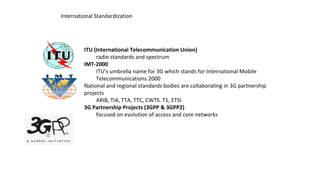
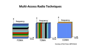
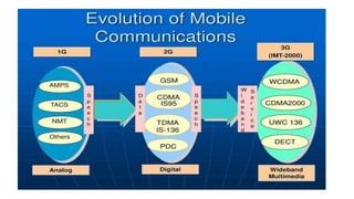
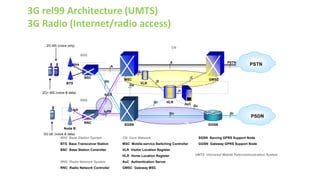
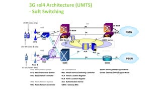
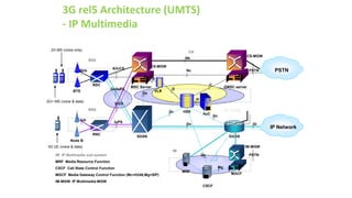
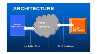
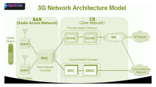
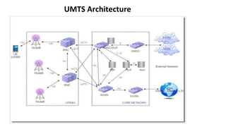
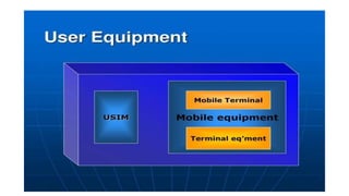
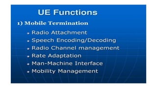
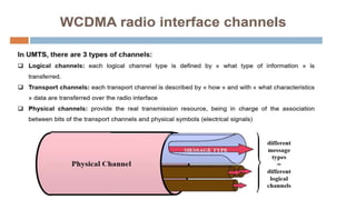
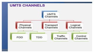
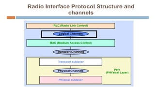
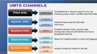
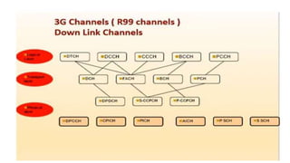
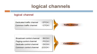
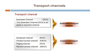
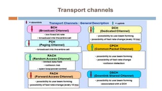
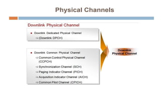
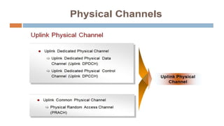
UMTS
3G architecture and air interface
MUGABO Thierry
Wireless Networks
International Standardization
ITU (International Telecommunication Union)
radio standards and spectrum
IMT-2000
ITU’s umbrella name for 3G which stands for International Mobile
Telecommunications 2000
National and regional standards bodies are collaborating in 3G partnership
projects
ARIB, TIA, TTA, TTC, CWTS. T1, ETSI
3G Partnership Projects (3GPP & 3GPP2)
focused on evolution of access and core networks
Multi-Access Radio Techniques
Courtesy of Petri Possi, UMTS World
First Generation – 1G Cellular
Advanced Mobile Phone Service (AMPS)
US trials 1978; deployed in Japan (’79) & US
(’83)
800 MHz band – two 20 MHz bands
Nordic Mobile Telephony (NMT)
Sweden, Norway, Demark & Finland
Launched 1981;
450 MHz; later at 900 MHz (NMT900)
Total Access Communications System (TACS)
British design; similar to AMPS; deployed 1985
Second Generation – 2G
Digital systems
Leveraged technology to increase capacity
Speech compression; digital signal processing
Utilized “Intelligent Network” concepts
Improved fraud prevention
Added new services
Wide diversity of 2G systems
IS-54/ IS-136 North American TDMA; PDC (Japan)
iDEN
DECT and PHS
IS-95 CDMA (cdmaOne)
GSM
BSS Base Station System
BTS Base Transceiver Station
BSC Base Station Controller
MS Mobile Station
NSS Network Sub-System
MSC Mobile-service Switching Controller
VLR Visitor Location Register
HLR Home Location Register
AuC Authentication Server
GMSC Gateway MSC
GSM 2G Architecture
SS7
BTS
BSC
MSC
VLR
HLR
AuC
GMSC
BSS
PSTN
NSS
A
E
C
D
PSTN
Abis
B
H
MS
GSM Global System for Mobile communication
IMT-2000 Radio Standards (3G)
IMT-SC* Single Carrier (UWC-136): EDGE
GSM evolution (TDMA); 200 KHz channels; sometimes called “2.75G”
IMT-MC* Multi Carrier CDMA: CDMA2000
Evolution of IS-95 CDMA, i.e. cdmaOne
IMT-DS* Direct Spread CDMA: W-CDMA
New from 3GPP; UTRAN FDD
IMT-TC** Time Code CDMA
New from 3GPP; UTRAN TDD
New from China; TD-SCDMA
IMT-FT** FDMA/TDMA (DECT legacy)
* UTRAN: The new radio network architecture being adopted by the
GSM world
3G rel99 Architecture (UMTS)
3G Radio (Internet/radio access)
SS7
IP
BTS
BSC
MSC
VLR
HLR
AuC
GMSC
BSS
SGSN GGSN
PSTN
PSDN
CN
C
D
Gc
Gr
Gn Gi
Abis
Gs
B
H
BSS Base Station System
BTS Base Transceiver Station
BSC Base Station Controller
RNS Radio Network System
RNC Radio Network Controller
CN Core Network
MSC Mobile-service Switching Controller
VLR Visitor Location Register
HLR Home Location Register
AuC Authentication Server
GMSC Gateway MSC
SGSN Serving GPRS Support Node
GGSN Gateway GPRS Support Node
A
E PSTN
2G MS (voice only)
2G+ MS (voice & data)
UMTS Universal Mobile Telecommunication System
Gb
3G UE (voice & data)
Node B
RNC
RNS
Iub
IuCS
ATM
IuPS
3G rel4 Architecture (UMTS)
- Soft Switching
SS7
IP/ATM
BTS
BSC
MSC Server
VLR
HLR
AuC
GMSC server
BSS
SGSN GGSN
PSTN
PSDN
CN
C
D
Gc
Gr
Gn Gi
Gb
Abis
Gs
B
H
BSS Base Station System
BTS Base Transceiver Station
BSC Base Station Controller
RNS Radio Network System
RNC Radio Network Controller
CN Core Network
MSC Mobile-service Switching Controller
VLR Visitor Location Register
HLR Home Location Register
AuC Authentication Server
GMSC Gateway MSC
SGSN Serving GPRS Support Node
GGSN Gateway GPRS Support Node
A
Nc
2G MS (voice only)
2G+ MS (voice & data)
Node B
RNC
RNS
Iub
IuCS
IuPS
3G UE (voice & data)
Mc
CS-MGW
CS-MGW
Nb
PSTN
Mc
ATM
3G rel5 Architecture (UMTS)
- IP Multimedia
Gb/IuPS
A/IuCS
SS7
IP/ATM
BTS
BSC
MSC Server
VLR
HSS
AuC
GMSC server
BSS
SGSN GGSN
PSTN
CN
C
D
Gc
Gr
Gn Gi
Abis
Gs
B
H
IM IP Multimedia sub-system
MRF Media Resource Function
CSCF Call State Control Function
MGCF Media Gateway Control Function (Mc=H248,Mg=SIP)
IM-MGW IP Multimedia-MGW
Nc
2G MS (voice only)
2G+ MS (voice & data)
Node B
RNC
RNS
Iub
3G UE (voice & data)
Mc
CS-MGW
CS-MGW
Nb
PSTN
Mc
IuCS
IuPS
ATM
IM
IP
PSTN
Mc
MGCF
IM-MGW
MRF
CSCF
Mg
Gs
IP Network
UMTS Architecture
Considered as a reference signal for error rate
Contains power control and BS code informatio
Contains frame start and slot start
information
Contains network name, country code,
routing area code and cell identity information
(broadcast channel)
Search for mobile location in which cell (paging)
random access for mobile on the cell
• Logical Channels
Logical channels are used to separate different kinds of data flows that have to be
transferred over the air interface.
The channels contain no information on how the data is later transmitted over the air.
• The BCCH (Broadcast Control Channel): This channel is monitored by all
mobile devices in Idle state to receive general system information from the network.
The parameters are further grouped into System Information Block (SIB) messages to
help the mobile device to decode the information and to save air interface
bandwidth.
• The PCCH (Paging Control Channel): This channel is used to inform
users of incoming calls or SMS messages. Paging messages are also used for
packet-switched calls if new data arrives from the network once all physical
resources (channels) for a subscriber have been released owing to a long period of
inactivity.
• The CCCH (Common Control Channel): This channel is used for all
messages from and to individual mobile devices (bidirectional) that want to establish
a new connection with the network.
–The DCCH (Dedicated Control Channel): a DCCH only transports data for a single
subscriber. For example, to transport messages for the MM and CC protocols for circuit-
switched services, Packet Mobility Management (PMM) and SM messages for packet-
switched services from and to the MSC and SGSN.
–The DTCH (Dedicated Traffic Channel): This channel is used for user data transfer
between
the network and a single user.
–The CTCH (Common Traffic Channel): This channel is used for cell broadcast
information.
• Transport Channels
Transport channels prepare downlink data frames for transmission over the air interface
by splitting them up into smaller parts, which are encapsulated into RLC/MAC-frames that
are more suitable for transmission over the air interface. The RLC/MAC header that is placed
in front of each frame contains, among other things, the following information:
• length of the frame (10, 20, 40 or 80 milliseconds);
• type of integrity checking mechanism (CRC checksum);
• channel coding format for error detection and correction;
• rate matching in case the speed of the physical channel and the layers above do not match;
•control information for detection of discontinuous transmission (DTX) in case the other end
has no
data to send at a particular time.
• The BCH (Broadcast Channel): Transport channel variant of the logical BCCH.
• The DCH (Dedicated Channel): This transport channel combines data from the
logical DTCH and the logical DCCH. The channel exists in both uplink and downlink
directions as data is exchanged in both directions.
• The PCH (Paging Channel): Transport channel variant of the logical PCCH.
• The FACH (Forward Access Channel): This channel is used by the network
to send RRC Connection Setup messages to mobile devices, which have
indicated via the RACH that they wish to establish a connection with the network. The
message contains information for the mobile device on how to access the
network. If the network has assigned a dedicated channel, the message contains, for
example, information on which spreading codes will be used in uplink and downlink
directions.
• The RACH (Random Access Channel): The
bidirectional logical CCCH is called RACH on the transport layer in uplink
direction. This channel is used by mobile devices to send RRC
Connection Request messages to the network if they wish to establish
a dedicated connection with the network (e.g. to establish a voice call).
Furthermore, the channel is used by mobile devices to send user packet
data (in Cell-FACH state) if no dedicated channel exists between the
mobile device and the network. It should be noted, however, that this
channel is only suitable for small amounts of data.
• Physical Channels: are responsible for offering a
physical transmission medium for one or more transport
channels. Furthermore, physical channels are responsible for
channel coding.
• The P-CCPCH (Primary Common Control Physical Channel): This channel is used
for distributing broadcast information in a cell.
• The S-CCPCH (Secondary Common Control Physical Channel): This channel is used
to broadcast the PCH and the FACH.
• The PRACH (Physical Random Access Channel): The physical implementation of the
RACH.
• The AICH (Acquisition Indication Channel): This channel is not shown in the channel
overview figures as there is no mapping of this channel to a transport channel. The
channel is used exclusively together with the PRACH during the connection
establishment of a mobile device with the network.
• The DPDCH (Dedicated Physical Data Channel): This channel is the physical
counterpart of a dedicated channel to a single mobile device. The channel combines user data
and signaling messages from (Packet) MM, CC and SM.
• The DPCCH (Dedicated Physical Control Channel): This channel is
used in addition to a DPDCH in both uplink and downlink directions. It contains layer
1 information like Transmit Power Control (TPC) bits for adjusting the
transmission power. Furthermore, the channel is also used to transmit the so-
called pilot bits. These bits always have the same value and can thus be used by
the receiver to generate a channel estimation, which is used to decode the remaining
bits of the DPCCH and the DPDCH.
3G Network architecture and channel.pptx

3G Network architecture and channel.pptx

  • 1.
    UMTS 3G architecture andair interface MUGABO Thierry Wireless Networks
  • 2.
    International Standardization ITU (InternationalTelecommunication Union) radio standards and spectrum IMT-2000 ITU’s umbrella name for 3G which stands for International Mobile Telecommunications 2000 National and regional standards bodies are collaborating in 3G partnership projects ARIB, TIA, TTA, TTC, CWTS. T1, ETSI 3G Partnership Projects (3GPP & 3GPP2) focused on evolution of access and core networks
  • 3.
    Multi-Access Radio Techniques Courtesyof Petri Possi, UMTS World
  • 7.
    First Generation –1G Cellular Advanced Mobile Phone Service (AMPS) US trials 1978; deployed in Japan (’79) & US (’83) 800 MHz band – two 20 MHz bands Nordic Mobile Telephony (NMT) Sweden, Norway, Demark & Finland Launched 1981; 450 MHz; later at 900 MHz (NMT900) Total Access Communications System (TACS) British design; similar to AMPS; deployed 1985
  • 8.
    Second Generation –2G Digital systems Leveraged technology to increase capacity Speech compression; digital signal processing Utilized “Intelligent Network” concepts Improved fraud prevention Added new services Wide diversity of 2G systems IS-54/ IS-136 North American TDMA; PDC (Japan) iDEN DECT and PHS IS-95 CDMA (cdmaOne) GSM
  • 9.
    BSS Base StationSystem BTS Base Transceiver Station BSC Base Station Controller MS Mobile Station NSS Network Sub-System MSC Mobile-service Switching Controller VLR Visitor Location Register HLR Home Location Register AuC Authentication Server GMSC Gateway MSC GSM 2G Architecture SS7 BTS BSC MSC VLR HLR AuC GMSC BSS PSTN NSS A E C D PSTN Abis B H MS GSM Global System for Mobile communication
  • 10.
    IMT-2000 Radio Standards(3G) IMT-SC* Single Carrier (UWC-136): EDGE GSM evolution (TDMA); 200 KHz channels; sometimes called “2.75G” IMT-MC* Multi Carrier CDMA: CDMA2000 Evolution of IS-95 CDMA, i.e. cdmaOne IMT-DS* Direct Spread CDMA: W-CDMA New from 3GPP; UTRAN FDD IMT-TC** Time Code CDMA New from 3GPP; UTRAN TDD New from China; TD-SCDMA IMT-FT** FDMA/TDMA (DECT legacy) * UTRAN: The new radio network architecture being adopted by the GSM world
  • 11.
    3G rel99 Architecture(UMTS) 3G Radio (Internet/radio access) SS7 IP BTS BSC MSC VLR HLR AuC GMSC BSS SGSN GGSN PSTN PSDN CN C D Gc Gr Gn Gi Abis Gs B H BSS Base Station System BTS Base Transceiver Station BSC Base Station Controller RNS Radio Network System RNC Radio Network Controller CN Core Network MSC Mobile-service Switching Controller VLR Visitor Location Register HLR Home Location Register AuC Authentication Server GMSC Gateway MSC SGSN Serving GPRS Support Node GGSN Gateway GPRS Support Node A E PSTN 2G MS (voice only) 2G+ MS (voice & data) UMTS Universal Mobile Telecommunication System Gb 3G UE (voice & data) Node B RNC RNS Iub IuCS ATM IuPS
  • 12.
    3G rel4 Architecture(UMTS) - Soft Switching SS7 IP/ATM BTS BSC MSC Server VLR HLR AuC GMSC server BSS SGSN GGSN PSTN PSDN CN C D Gc Gr Gn Gi Gb Abis Gs B H BSS Base Station System BTS Base Transceiver Station BSC Base Station Controller RNS Radio Network System RNC Radio Network Controller CN Core Network MSC Mobile-service Switching Controller VLR Visitor Location Register HLR Home Location Register AuC Authentication Server GMSC Gateway MSC SGSN Serving GPRS Support Node GGSN Gateway GPRS Support Node A Nc 2G MS (voice only) 2G+ MS (voice & data) Node B RNC RNS Iub IuCS IuPS 3G UE (voice & data) Mc CS-MGW CS-MGW Nb PSTN Mc ATM
  • 13.
    3G rel5 Architecture(UMTS) - IP Multimedia Gb/IuPS A/IuCS SS7 IP/ATM BTS BSC MSC Server VLR HSS AuC GMSC server BSS SGSN GGSN PSTN CN C D Gc Gr Gn Gi Abis Gs B H IM IP Multimedia sub-system MRF Media Resource Function CSCF Call State Control Function MGCF Media Gateway Control Function (Mc=H248,Mg=SIP) IM-MGW IP Multimedia-MGW Nc 2G MS (voice only) 2G+ MS (voice & data) Node B RNC RNS Iub 3G UE (voice & data) Mc CS-MGW CS-MGW Nb PSTN Mc IuCS IuPS ATM IM IP PSTN Mc MGCF IM-MGW MRF CSCF Mg Gs IP Network
  • 17.
  • 36.
    Considered as areference signal for error rate Contains power control and BS code informatio Contains frame start and slot start information Contains network name, country code, routing area code and cell identity information (broadcast channel) Search for mobile location in which cell (paging) random access for mobile on the cell
  • 39.
    • Logical Channels Logicalchannels are used to separate different kinds of data flows that have to be transferred over the air interface. The channels contain no information on how the data is later transmitted over the air.
  • 40.
    • The BCCH(Broadcast Control Channel): This channel is monitored by all mobile devices in Idle state to receive general system information from the network. The parameters are further grouped into System Information Block (SIB) messages to help the mobile device to decode the information and to save air interface bandwidth. • The PCCH (Paging Control Channel): This channel is used to inform users of incoming calls or SMS messages. Paging messages are also used for packet-switched calls if new data arrives from the network once all physical resources (channels) for a subscriber have been released owing to a long period of inactivity.
  • 41.
    • The CCCH(Common Control Channel): This channel is used for all messages from and to individual mobile devices (bidirectional) that want to establish a new connection with the network. –The DCCH (Dedicated Control Channel): a DCCH only transports data for a single subscriber. For example, to transport messages for the MM and CC protocols for circuit- switched services, Packet Mobility Management (PMM) and SM messages for packet- switched services from and to the MSC and SGSN. –The DTCH (Dedicated Traffic Channel): This channel is used for user data transfer between the network and a single user. –The CTCH (Common Traffic Channel): This channel is used for cell broadcast information.
  • 44.
    • Transport Channels Transportchannels prepare downlink data frames for transmission over the air interface by splitting them up into smaller parts, which are encapsulated into RLC/MAC-frames that are more suitable for transmission over the air interface. The RLC/MAC header that is placed in front of each frame contains, among other things, the following information: • length of the frame (10, 20, 40 or 80 milliseconds); • type of integrity checking mechanism (CRC checksum); • channel coding format for error detection and correction; • rate matching in case the speed of the physical channel and the layers above do not match; •control information for detection of discontinuous transmission (DTX) in case the other end has no data to send at a particular time.
  • 45.
    • The BCH(Broadcast Channel): Transport channel variant of the logical BCCH. • The DCH (Dedicated Channel): This transport channel combines data from the logical DTCH and the logical DCCH. The channel exists in both uplink and downlink directions as data is exchanged in both directions. • The PCH (Paging Channel): Transport channel variant of the logical PCCH. • The FACH (Forward Access Channel): This channel is used by the network to send RRC Connection Setup messages to mobile devices, which have indicated via the RACH that they wish to establish a connection with the network. The message contains information for the mobile device on how to access the network. If the network has assigned a dedicated channel, the message contains, for example, information on which spreading codes will be used in uplink and downlink directions.
  • 46.
    • The RACH(Random Access Channel): The bidirectional logical CCCH is called RACH on the transport layer in uplink direction. This channel is used by mobile devices to send RRC Connection Request messages to the network if they wish to establish a dedicated connection with the network (e.g. to establish a voice call). Furthermore, the channel is used by mobile devices to send user packet data (in Cell-FACH state) if no dedicated channel exists between the mobile device and the network. It should be noted, however, that this channel is only suitable for small amounts of data.
  • 48.
    • Physical Channels:are responsible for offering a physical transmission medium for one or more transport channels. Furthermore, physical channels are responsible for channel coding.
  • 51.
    • The P-CCPCH(Primary Common Control Physical Channel): This channel is used for distributing broadcast information in a cell. • The S-CCPCH (Secondary Common Control Physical Channel): This channel is used to broadcast the PCH and the FACH. • The PRACH (Physical Random Access Channel): The physical implementation of the RACH. • The AICH (Acquisition Indication Channel): This channel is not shown in the channel overview figures as there is no mapping of this channel to a transport channel. The channel is used exclusively together with the PRACH during the connection establishment of a mobile device with the network.
  • 52.
    • The DPDCH(Dedicated Physical Data Channel): This channel is the physical counterpart of a dedicated channel to a single mobile device. The channel combines user data and signaling messages from (Packet) MM, CC and SM. • The DPCCH (Dedicated Physical Control Channel): This channel is used in addition to a DPDCH in both uplink and downlink directions. It contains layer 1 information like Transmit Power Control (TPC) bits for adjusting the transmission power. Furthermore, the channel is also used to transmit the so- called pilot bits. These bits always have the same value and can thus be used by the receiver to generate a channel estimation, which is used to decode the remaining bits of the DPCCH and the DPDCH.