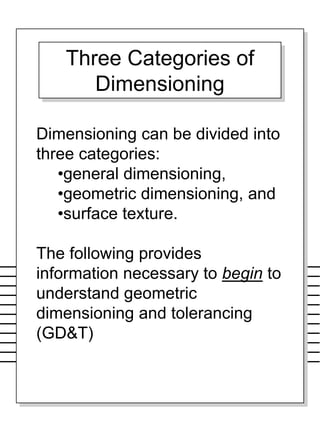
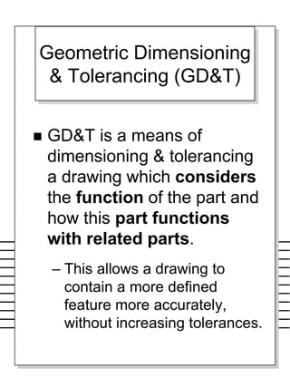
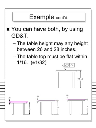
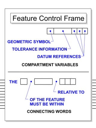
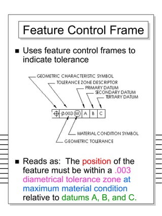
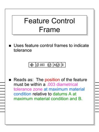
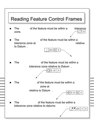
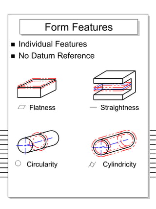
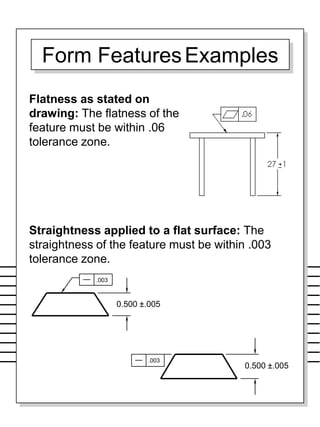
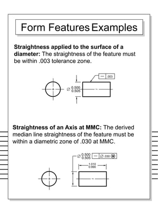
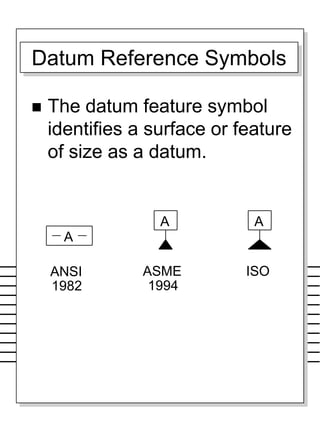
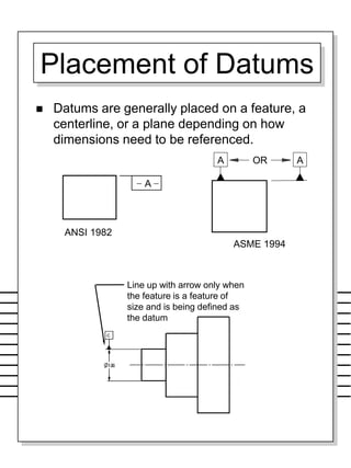
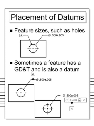
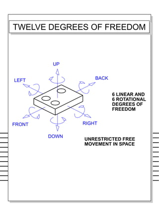
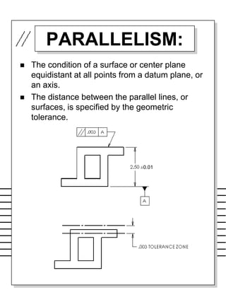
This document provides information about geometric dimensioning and tolerancing (GD&T). It begins by explaining the three categories of dimensioning and then defines GD&T as considering the function of a part and how it interacts with related parts. This allows for more precise dimensioning without increasing tolerances. The document then discusses important GD&T concepts like datums, feature control frames, and how they are used to specify tolerances and dimensions. It also provides examples of how different GD&T features like flatness and straightness are applied.
GD&T is a means of dimensioning & tolerancing a drawing which considers the function of the part and how this part functions with related parts.
GD&T has increased in practice in last 15 years because of ISO 9000.
ISO 9000 requires not only that something be required, but how it is to be controlled. For example, how round does a round feature have to be?
GD&T is a system that uses standard symbols to indicate tolerances that are based on the feature’s geometry.
Sometimes called feature based dimensioning & tolerancing or true position dimensioning & tolerancing
GD&T practices are specified in ANSI Y14.5M-1994.
Medición de los parámetros "twist" de rugosidad, nuevos requerimientos de medición en la industria automotriz. Jenoptik a incorporado la metodología y evaluación de este parámetro en nuestros software.
Sachpazis:Terzaghi Bearing Capacity Estimation in simple terms with Calculati...Dr.Costas Sachpazis
Terzaghi's soil bearing capacity theory, developed by Karl Terzaghi, is a fundamental principle in geotechnical engineering used to determine the bearing capacity of shallow foundations. This theory provides a method to calculate the ultimate bearing capacity of soil, which is the maximum load per unit area that the soil can support without undergoing shear failure. The Calculation HTML Code included.
Student information management system project report ii.pdfKamal Acharya
Our project explains about the student management. This project mainly explains the various actions related to student details. This project shows some ease in adding, editing and deleting the student details. It also provides a less time consuming process for viewing, adding, editing and deleting the marks of the students.
Hybrid optimization of pumped hydro system and solar- Engr. Abdul-Azeez.pdffxintegritypublishin
Advancements in technology unveil a myriad of electrical and electronic breakthroughs geared towards efficiently harnessing limited resources to meet human energy demands. The optimization of hybrid solar PV panels and pumped hydro energy supply systems plays a pivotal role in utilizing natural resources effectively. This initiative not only benefits humanity but also fosters environmental sustainability. The study investigated the design optimization of these hybrid systems, focusing on understanding solar radiation patterns, identifying geographical influences on solar radiation, formulating a mathematical model for system optimization, and determining the optimal configuration of PV panels and pumped hydro storage. Through a comparative analysis approach and eight weeks of data collection, the study addressed key research questions related to solar radiation patterns and optimal system design. The findings highlighted regions with heightened solar radiation levels, showcasing substantial potential for power generation and emphasizing the system's efficiency. Optimizing system design significantly boosted power generation, promoted renewable energy utilization, and enhanced energy storage capacity. The study underscored the benefits of optimizing hybrid solar PV panels and pumped hydro energy supply systems for sustainable energy usage. Optimizing the design of solar PV panels and pumped hydro energy supply systems as examined across diverse climatic conditions in a developing country, not only enhances power generation but also improves the integration of renewable energy sources and boosts energy storage capacities, particularly beneficial for less economically prosperous regions. Additionally, the study provides valuable insights for advancing energy research in economically viable areas. Recommendations included conducting site-specific assessments, utilizing advanced modeling tools, implementing regular maintenance protocols, and enhancing communication among system components.
Immunizing Image Classifiers Against Localized Adversary Attacksgerogepatton
This paper addresses the vulnerability of deep learning models, particularly convolutional neural networks
(CNN)s, to adversarial attacks and presents a proactive training technique designed to counter them. We
introduce a novel volumization algorithm, which transforms 2D images into 3D volumetric representations.
When combined with 3D convolution and deep curriculum learning optimization (CLO), itsignificantly improves
the immunity of models against localized universal attacks by up to 40%. We evaluate our proposed approach
using contemporary CNN architectures and the modified Canadian Institute for Advanced Research (CIFAR-10
and CIFAR-100) and ImageNet Large Scale Visual Recognition Challenge (ILSVRC12) datasets, showcasing
accuracy improvements over previous techniques. The results indicate that the combination of the volumetric
input and curriculum learning holds significant promise for mitigating adversarial attacks without necessitating
adversary training.
1. PART PRODUCTION COMMUNICATION MODEL
MANAGEMENT
DESIGN
TOOLING
PRODUCTION
INSPECTION
ASSEMBLY
ROUTING
PLANNING
PRICING
SERVICE
PURCHASING
SALES
CUSTOMERS
VENDORS
Geometric Dimensioning
and Tolerancing (GD&T)
2. Dimensioning can be divided into
three categories:
•general dimensioning,
•geometric dimensioning, and
•surface texture.
The following provides
information necessary to begin to
understand geometric
dimensioning and tolerancing
(GD&T)
Three Categories of
Dimensioning
6. Geometric Dimensioning
& Tolerancing (GD&T)
GD&T is a means of
dimensioning & tolerancing
a drawing which considers
the function of the part and
how this part functions
with related parts.
– This allows a drawing to
contain a more defined
feature more accurately,
without increasing tolerances.
7. For Example
Given Table Height
However, all surfaces have a degree of
waviness, or smoothness. For
example, the surface of a 2 x 4 is much
wavier (rough) than the surface of a
piece of glass.
– As the table height is dimensioned, the
following table would pass inspection.
If top must be flatter, you could tighten
the tolerance to ± 1/32.
– However, now the height is restricted to
26.97 to 27.03 meaning good tables would
be rejected.
Assume all 4 legs will be
cut to length at the same
time.
or
8. Example cont’d.
You can have both, by using
GD&T.
– The table height may any height
between 26 and 28 inches.
– The table top must be flat within
1/16. (±1/32)
27
.06
26
.06
28
.06
9. WHY IS GD&T IMPORTANT
Saves money
– For example, if large number
of parts are being made –
GD&T can reduce or eliminate
inspection of some features.
Ensures design, dimension, and
tolerance requirements as they
relate to the actual function
Ensures interchangeability of
mating parts at the assembly
Provides uniformity
It is a universal understanding of
the symbols instead of words
10. WHEN TO USE GD&T
When part features are critical to
a function or interchangeability
When functional gaging is
desirable
When datum references are
desirable to ensure consistency
between design
When standard interpretation or
tolerance is not already implied
When it allows a better choice of
machining processes to be made
for production of a part
11. TERMINOLOGY REVIEW
Maximum Material Condition
(MMC): The condition where a size
feature contains the maximum amount
of material within the stated limits of
size. I.e., largest shaft and smallest
hole.
Least Material Condition (LMC): The
condition where a size feature
contains the least amount of material
within the stated limits of size. I.e.,
smallest shaft and largest hole.
Tolerance: Difference between MMC
and LMC limits of a single dimension.
Allowance: Difference between the
MMC of two mating parts. (Minimum
clearance and maximum interference)
Basic Dimension: Nominal
dimension from which tolerances are
derived.
13. SIZE DIMENSION
MMC
LMC
ENVELOPE OF SIZE
(2.003)
(2.007)
ENVELOPE PRINCIPLE
LIMITS OF SIZE
A variation in form is allowed
between the least material
condition (LMC) and the
maximum material condition
(MMC).
Envelop Principle defines the
size and form relationships
between mating parts.
19. Characteristics & Symbols
cont’d.
– Maximum Material Condition MMC
– Regardless of Feature Size RFS
– Least Material Condition LMC
– Projected Tolerance Zone
– Diametrical (Cylindrical) Tolerance
Zone or Feature
– Basic, or Exact, Dimension
– Datum Feature Symbol
– Feature Control Frame
21. Feature Control Frame
Uses feature control frames to
indicate tolerance
Reads as: The position of the
feature must be within a .003
diametrical tolerance zone at
maximum material condition
relative to datums A, B, and C.
22. Feature Control
Frame
Uses feature control frames to indicate
tolerance
Reads as: The position of the feature
must be within a .003 diametrical
tolerance zone at maximum material
condition relative to datums A at
maximum material condition and B.
23. The of the feature must be within a tolerance
zone.
The of the feature must be within a
tolerance zone at relative
to Datum .
The of the feature must be within a
tolerance zone relative to Datum .
The of the feature must be within a
zone at
relative to Datum .
The of the feature must be within a
tolerance zone relative to datums .
Reading Feature Control Frames
24. Placement of Feature
Control Frames
May be attached to a side, end
or corner of the symbol box to
an extension line.
Applied to surface.
Applied to axis
25. Placement of Feature
Control FramesCont’d.
May be below or closely
adjacent to the dimension or
note pertaining to that feature.
Ø .500±.005
26. Basic Dimension
A theoretically exact size, profile,
orientation, or location of a feature or
datum target, therefore, a basic
dimension is untoleranced.
Most often used with position,
angularity, and profile)
Basic dimensions have a rectangle
surrounding it.
1.000
29. Form FeaturesExamples
Flatness as stated on
drawing: The flatness of the
feature must be within .06
tolerance zone.
.003
0.500 ±.005
.003
0.500 ±.005
Straightness applied to a flat surface: The
straightness of the feature must be within .003
tolerance zone.
30. Form FeaturesExamples
Straightness applied to the surface of a
diameter: The straightness of the feature must
be within .003 tolerance zone.
.003
0.500
0.505
Straightness of an Axis at MMC: The derived
median line straightness of the feature must be
within a diametric zone of .030 at MMC.
.030
0.500
0.505
M
1.010
0.990
33. Features that Require
Datum Reference
Orientation
– Perpendicularity
– Angularity
– Parallelism
Runout
– Circular Runout
– Total Runout
Location
– Position
– Concentricity
– Symmetry
34. Datum
Datums are features (points, axis,
and planes) on the object that are
used as reference surfaces from
which other measurements are
made. Used in designing, tooling,
manufacturing, inspecting, and
assembling components and sub-
assemblies.
– As you know, not every GD&T
feature requires a datum, i.e., Flat
1.000
35. Datums cont’d.
Features are identified with
respect to a datum.
Always start with the letter A
Do not use letters I, O, or Q
May use double letters AA,
BB, etc.
This information is located in
the feature control frame.
Datums on a drawing of a
part are represented using
the symbol shown below.
36. Datum Reference Symbols
The datum feature symbol
identifies a surface or feature
of size as a datum.
A
ISO
A
ANSI
1982
ASME
A
1994
37. Placement of Datums
Datums are generally placed on a feature, a
centerline, or a plane depending on how
dimensions need to be referenced.
A A
OR
ASME 1994
A
ANSI 1982
Line up with arrow only when
the feature is a feature of
size and is being defined as
the datum
38. Placement of Datums
Feature sizes, such as holes
Sometimes a feature has a
GD&T and is also a datum
Ø .500±.005
A
Ø .500±.005
A Ø .500±.005
39. 6 ROTATIONAL
6 LINEAR AND
FREEDOM
DEGREES OF
UP
DOWN
RIGHT
LEFT BACK
FRONT
UNRESTRICTED FREE
MOVEMENT IN SPACE
TWELVE DEGREES OF FREEDOM
40. Example Datums
Datums must be
perpendicular to each other
– Primary
– Secondary
– Tertiary Datum
41. Primary Datum
A primary datum is selected
to provide functional
relationships, accessibility,
and repeatability.
– Functional Relationships
» A standardization of size is desired in
the manufacturing of a part.
» Consideration of how parts are
orientated to each other is very
important.
– For example, legos are made in a
standard size in order to lock into
place. A primary datum is chosen
to reference the location of the
mating features.
– Accessibility
» Does anything, such as, shafts, get in
the way?
42. Primary Datum cont’d.
– Repeatability
For example, castings, sheet
metal, etc.
» The primary datum chosen must
insure precise measurements.
The surface established must
produce consistent
» Measurements when producing
many identical parts to meet
requirements specified.
43. FIRST DATUM ESTABLISHED
BY THREE POINTS (MIN)
CONTACT WITH SIMULATED
DATUM A
Primary Datum
Restricts 6 degrees of freedom
44. Secondary &
Tertiary Datums
All dimension may not be capable to
reference from the primary datum to
ensure functional relationships,
accessibility, and repeatability.
– Secondary Datum
» Secondary datums are produced
perpendicular to the primary datum so
measurements can be referenced from
them.
– Tertiary Datum
» This datum is always perpendicular to
both the primary and secondary datums
ensuring a fixed position from three
related parts.
45. SECOND DATUM
PLANE ESTABLISHED BY
TWO POINTS (MIN) CONTACT
WITH SIMULATED DATUM B
Secondary Datum
Restricts 10 degrees of freedom.
46. Tertiary Datum
Restricts 12 degrees of freedom.
90°
THIRD DATUM
PLANE ESTABLISHED
BY ONE POINT (MIN)
CONTACT WITH
SIMULATED DATUM C
MEASURING DIRECTIONS FOR
RELATED DIMENSIONS
51. PERPENDICULARITY:
is the condition of a surface, center plane, or
axis at a right angle (90°) to a datum plane or
axis.
Ex:
The tolerance zone is the
space between the 2
parallel lines. They are
perpendicular to the
datum plane and spaced
.005 apart.
The perpendicularity of
this surface must be
within a .005 tolerance
zone relative to datum A.
52. Practice Problem
Plane 1 must be
perpendicular within .005
tolerance zone to plane 2.
BOTTOM SURFACE
53. Practice Problem
Plane 1 must be
perpendicular within .005
tolerance zone to plane 2
BOTTOM PLANE
54. 2.00±.01
.02 Tolerance
Practice Problem
Without GD & T this
would be acceptable
2.00±.01
.02 Tolerance
.005 Tolerance
Zone
With GD & T the overall height may end
anywhere between the two blue planes. But the
bottom plane is restricted to the red tolerance
zone.
55. PERPENDICULARITY Cont’d.
Location of hole (axis)
This means ‘the hole
(axis) must be
perpendicular within a
diametrical tolerance
zone of .010 relative to
datum A’
56. ANGULARITY:
is the condition of a surface, axis, or
median plane which is at a specific
angle (other than 90°) from a datum
plane or axis.
Can be applied to an axis at MMC.
Typically must have a basic
dimension.
The surface is at a
45º angle with a
.005 tolerance zone
relative to datum A.
57. ±0.01
PARALLELISM:
The condition of a surface or center plane
equidistant at all points from a datum plane, or
an axis.
The distance between the parallel lines, or
surfaces, is specified by the geometric
tolerance.
58. Material Conditions
Maximum Material Condition
(MMC)
Least Material Condition
(LMC)
Regardless of Feature
Size(RFS)
59. Maximum Material Condition
MMC
This is when part will weigh the
most.
– MMC for a shaft is the largest
allowable size.
» MMC of Ø0.240±.005?
– MMC for a hole is the smallest
allowable size.
» MMC of Ø0.250±.005?
Permits greater possible
tolerance as the part feature
sizes vary from their calculated
MMC
Ensures interchangeability
Used
– With interrelated features with
respect to location
– Size, such as, hole, slot, pin, etc.
60. Least Material Condition
LMC
This is when part will weigh
the least.
– LMC for a shaft is the smallest
allowable size.
» LMC of Ø0.240±.005?
– LMC for a hole is the largest
allowable size.
» LMC of Ø0.250±.005?
61. Regardless of Feature Size
RFS
Requires that the condition of
the material NOT be
considered.
This is used when the size
feature does not affect the
specified tolerance.
Valid only when applied to
features of size, such as
holes, slots, pins, etc., with
an axis or center plane.
63. Position Tolerance
A position tolerance is the total
permissible variation in the location
of a feature about its exact true
position.
For cylindrical features, the
position tolerance zone is typically
a cylinder within which the axis of
the feature must lie.
For other features, the center plane
of the feature must fit in the space
between two parallel planes.
The exact position of the feature is
located with basic dimensions.
The position tolerance is typically
associated with the size tolerance
of the feature.
Datums are required.