Download as PDF, PPTX


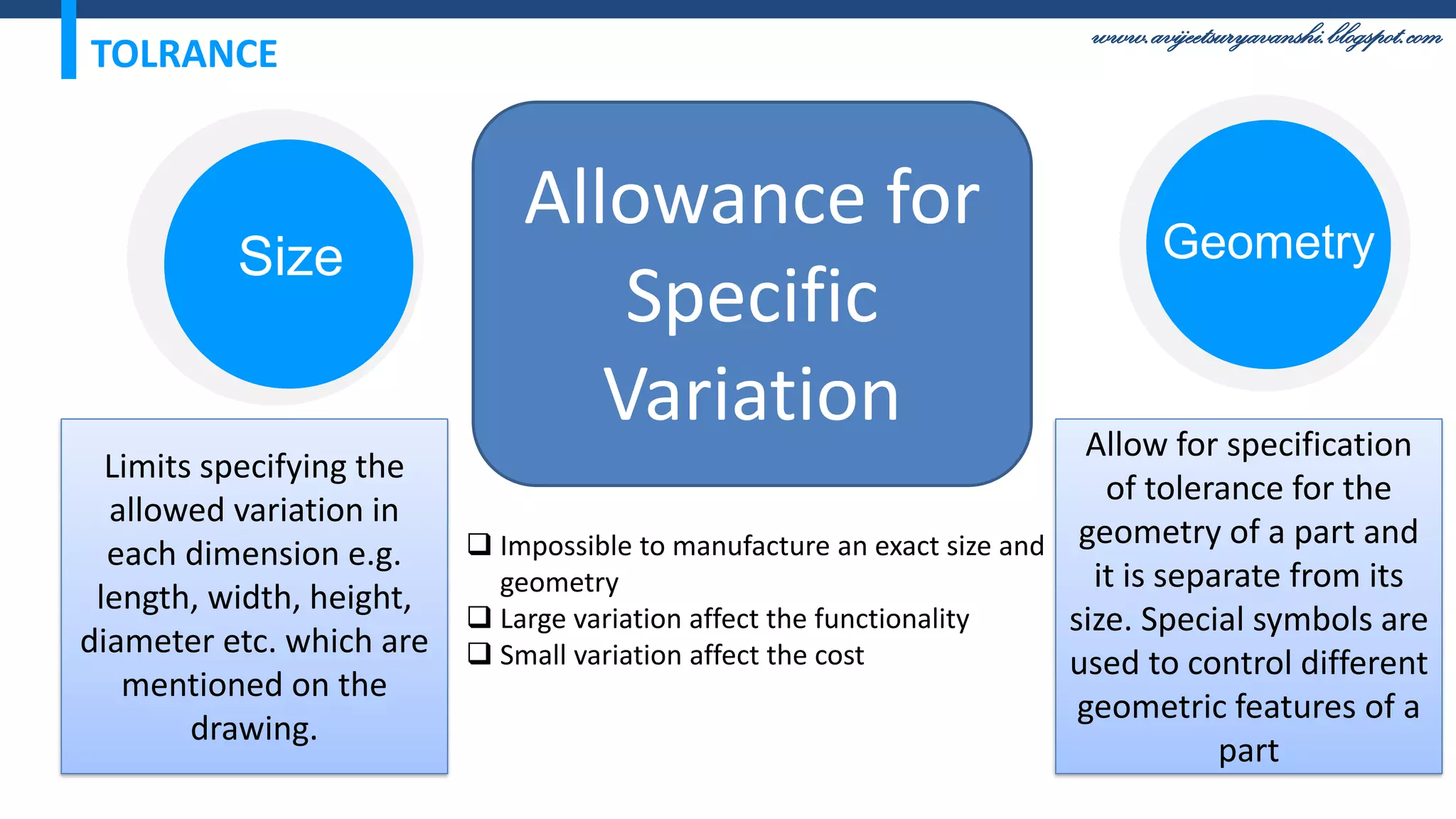

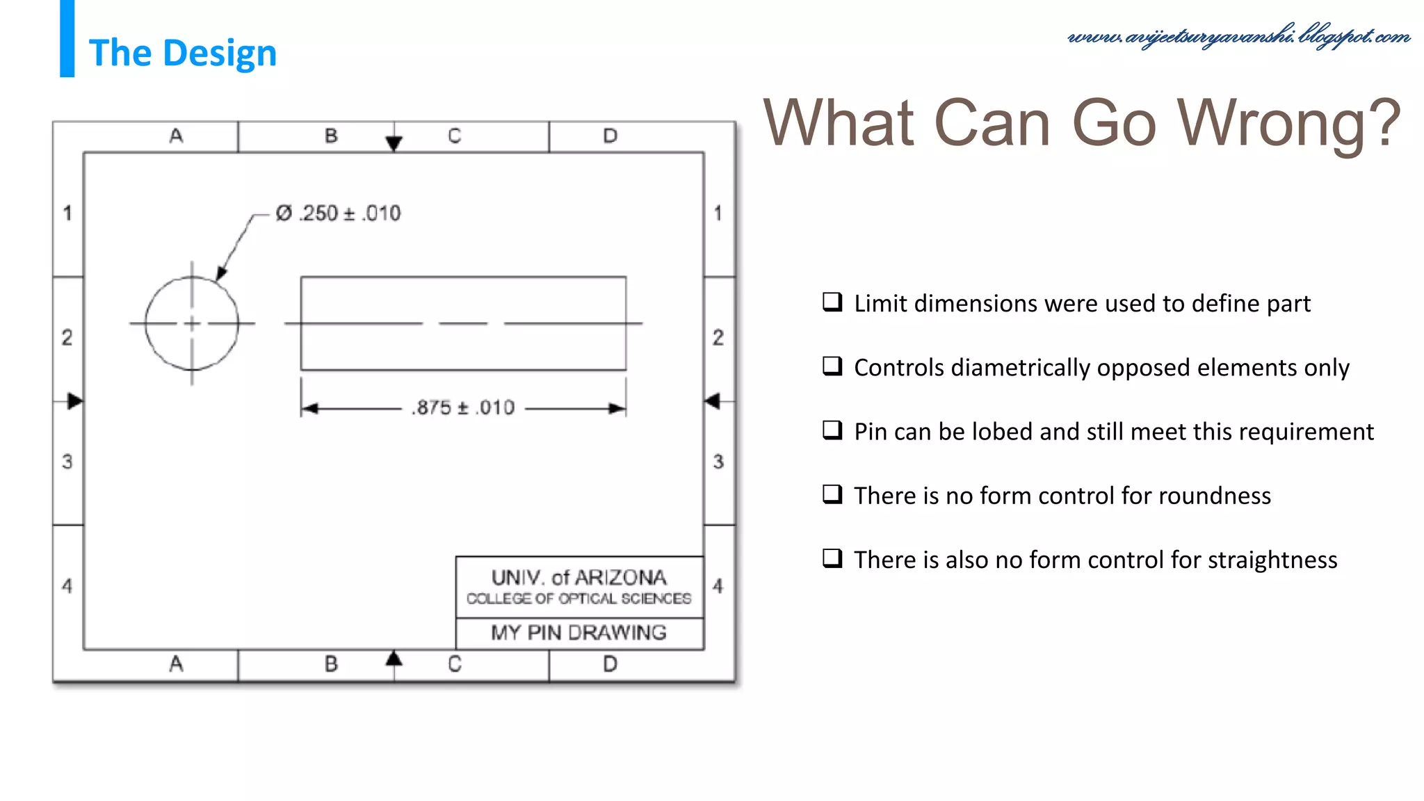

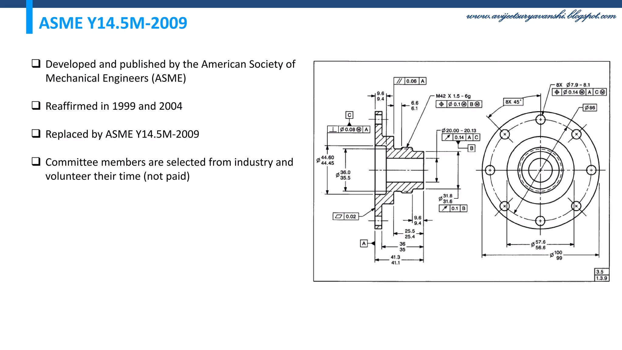
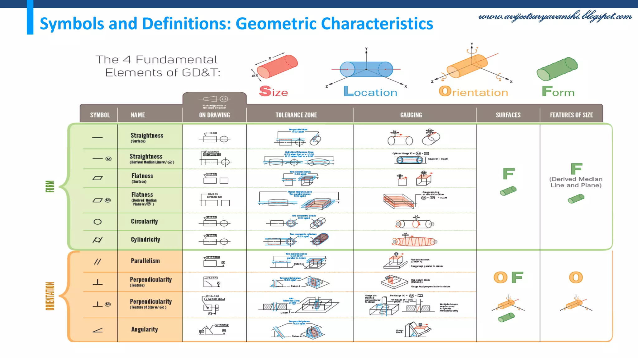


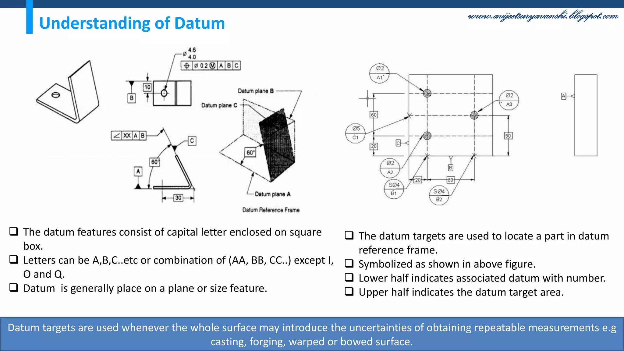


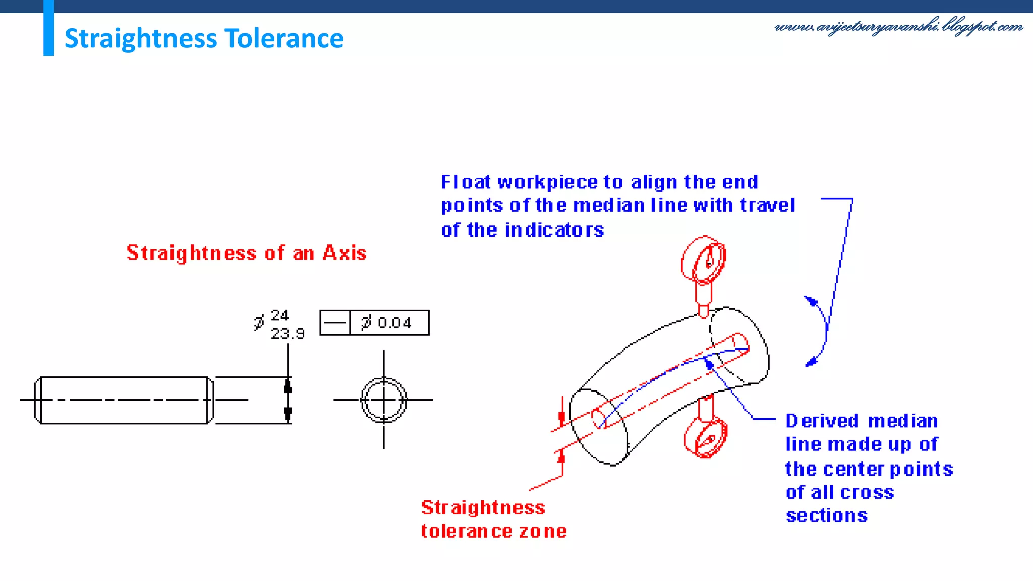
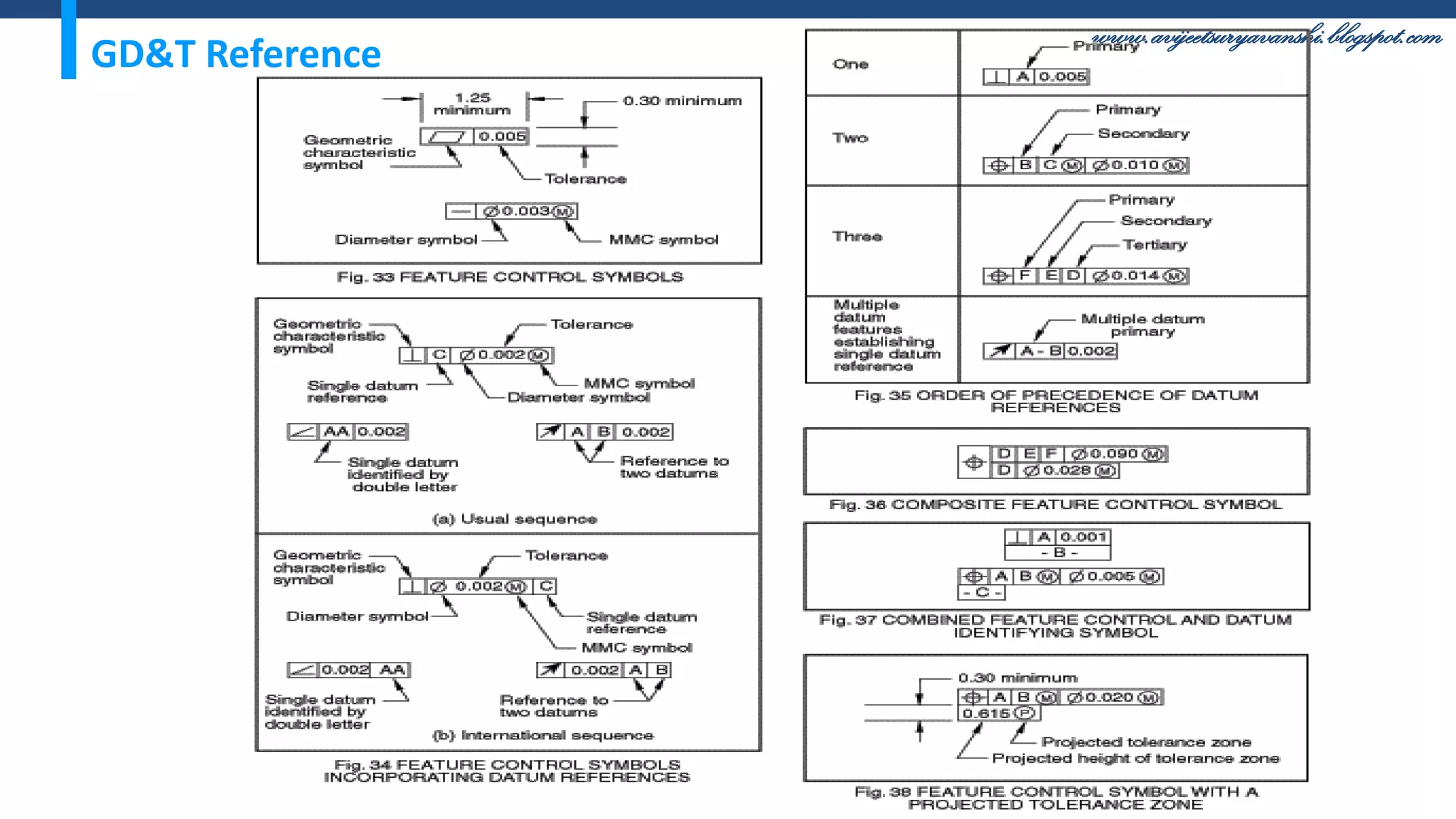
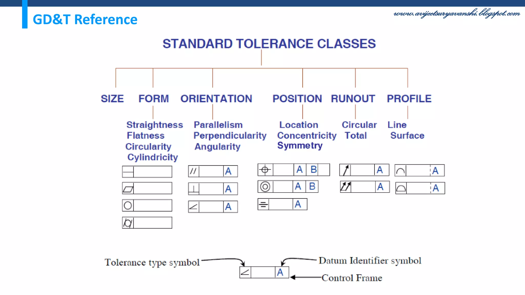


The document appears to be a blog about geometric dimensioning and tolerancing (GD&T) training. It provides an overview of GD&T concepts including size tolerancing, geometric tolerancing, benefits of GD&T, and introduces ASME Y14.5 which is the GD&T standard. It then discusses specific GD&T topics such as symbols, datum features, feature control frames, material conditions, and bonus tolerances. The blog aims to help readers understand the fundamentals and applications of GD&T.