Download to read offline
![Available functions for Nano 5 Cards
I2C (I2C_FUNC.c):
// I2C Functions – Master
void i2c_start (void)
void i2c_stop (void)
bit i2c_write (unsigned char output_data)
unsigned char i2c_read (bit send_ack)
LCD (LCD_Func.c):
void sendCharLCD (unsigned char DIR_DISP, unsigned char CONT_DISP)
void SendStringLCD (unsigned short int LINE, char src[])
Example:
char string1[] = "-----Reference------";
SendStringLCD (2, string1); // line(1-4), string
void Clear_Screen (void)
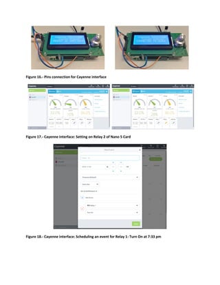
Figure 1.- LCD interface using I2C communication
Pins definition (Init.h):
Example:
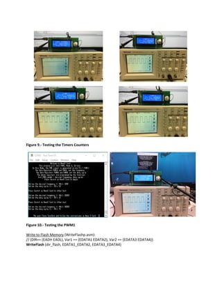
// Timers Tester & Cayenne Interface
sbit TEST_P23 = P2^3; // Control of Relay 1
sbit TEST_P22 = P2^2; // Control of Relay 2
sbit TEST_P21 = P2^1; // Reset
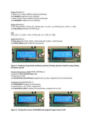
Initial conditions (BasicRut.c):
void System_Setup (void)
Example:
// %%%%%%%%%%%%%%%%%%%%%%%%%%%%%%%%%% UART Setup
// Initialize the serial port (115200, 8, N, 1) [see page 32 of data sheet]
PLLCON = 0x50;
SCON = 0x50; // 0101,0000 (Mode 1 and RxD enable)
T3CON = 0x83;
T3FD = 0x09;
TI = 1; // Set UART to send first char](https://image.slidesharecdn.com/functions-161108120502/85/Functions-for-Nano-5-Card-1-320.jpg)
![Available functions for Nano 5 Cards
I2C (I2C_FUNC.c):
// I2C Functions – Master
void i2c_start (void)
void i2c_stop (void)
bit i2c_write (unsigned char output_data)
unsigned char i2c_read (bit send_ack)
LCD (LCD_Func.c):
void sendCharLCD (unsigned char DIR_DISP, unsigned char CONT_DISP)
void SendStringLCD (unsigned short int LINE, char src[])
Example:
char string1[] = "-----Reference------";
SendStringLCD (2, string1); // line(1-4), string
void Clear_Screen (void)
Figure 1.- LCD interface using I2C communication
Pins definition (Init.h):
Example:
// Timers Tester & Cayenne Interface
sbit TEST_P23 = P2^3; // Control of Relay 1
sbit TEST_P22 = P2^2; // Control of Relay 2
sbit TEST_P21 = P2^1; // Reset
Initial conditions (BasicRut.c):
void System_Setup (void)
Example:
// %%%%%%%%%%%%%%%%%%%%%%%%%%%%%%%%%% UART Setup
// Initialize the serial port (115200, 8, N, 1) [see page 32 of data sheet]
PLLCON = 0x50;
SCON = 0x50; // 0101,0000 (Mode 1 and RxD enable)
T3CON = 0x83;
T3FD = 0x09;
TI = 1; // Set UART to send first char](https://image.slidesharecdn.com/functions-161108120502/75/Functions-for-Nano-5-Card-1-2048.jpg)
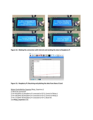

The document describes various functions available for the Nano 5 card including I2C communication, LCD display control, analog and digital I/O, ADC, DAC, timers, PWM, flash memory, real-time clock, and interfacing with a Raspberry Pi. It provides code examples to initialize and use functions for I2C, LCD, analog input, digital I/O, UART communication, flash memory reading and writing, and real-time clock time setting and reading. Diagrams depict the hardware setup and connections for testing various functions.


![[Deck] What's New in Spark-Iceberg Integration via DSV2.pptx](https://cdn.slidesharecdn.com/ss_thumbnails/deckwhatsnewinspark-icebergintegrationviadsv2-260210005337-25955b12-thumbnail.jpg?width=640&height=640&fit=bounds)


