The document describes an experiment in C programming for an ARM microcontroller, focusing on UART serial communication and temperature conversion functions. Key implementations include converting Celsius to Fahrenheit and printing temperature values based on user input. The document also discusses GPIO initialization, assembly code comparison, and concludes with insights into microcontroller data communication and programming differences between assembly language and C.


![• Recorded video for the same is present in below link
https://youtube.com/shorts/eEJTT30kyF4?feature=share
• Code inside the while infinite loop with above discussed logic is shown below:
while(1)
{
// Check whether UART0_BASE is nonzero which happens when any character is
input in terminal window.
if(UARTCharsAvail(UART0_BASE)){
// Store the character as InputChar variable
InputChar = UARTCharGetNonBlocking (UART0_BASE);
// Check for reading from temperature sensor only when C or F is entered
if (InputChar == 'C' || InputChar == 'F'){
// Trigger the ADC conversion.
ADCProcessorTrigger(ADC0_BASE, 1);
// Wait for conversion to be completed.
while(!ADCIntStatus(ADC0_BASE, 1, false))
{
}
// Clear the ADC interrupt flag.
ADCIntClear(ADC0_BASE, 1);
// Read ADC Values.
ADCSequenceDataGet(ADC0_BASE, 1, ui32ADC0Value);
//Average the 4 Samples
ui32TempAvg = (ui32ADC0Value[0] + ui32ADC0Value[1] +
ui32ADC0Value[2] + ui32ADC0Value[3] + 2)/4;
//Convert Raw Data to Temp Celsius
ui32TempValueC = (1475 - ((2475 * ui32TempAvg)) / 4096)/10;
// Display the temperature value on the console.
PrintTemps(ui32TempValueC,InputChar);
}
// Enter into the if loop only when G is received and toggle the Green LED
if (InputChar == 'G'){
toggleGreenLED();
}
}
// This function provides a means of generating a constant length
// delay. The function delay (in cycles) = 3 * parameter. Delay
// 250ms arbitrarily.
//
SysCtlDelay(SysCtlClockGet() / clkscalevalue);
Below shown is the code for PrintTemps function:
//This function prints the temperatures in Celsius or Fahrenheit based on Char
variable value, to the console in an easy human readable format.
void PrintTemps (uint32_t TempC, uint8_t Char)
{](https://image.slidesharecdn.com/exp-3report-221025181405-892c5608/85/C-programming-of-an-ARM-microcontroller-and-writing-UART-serial-communication-protocol-4-320.jpg)

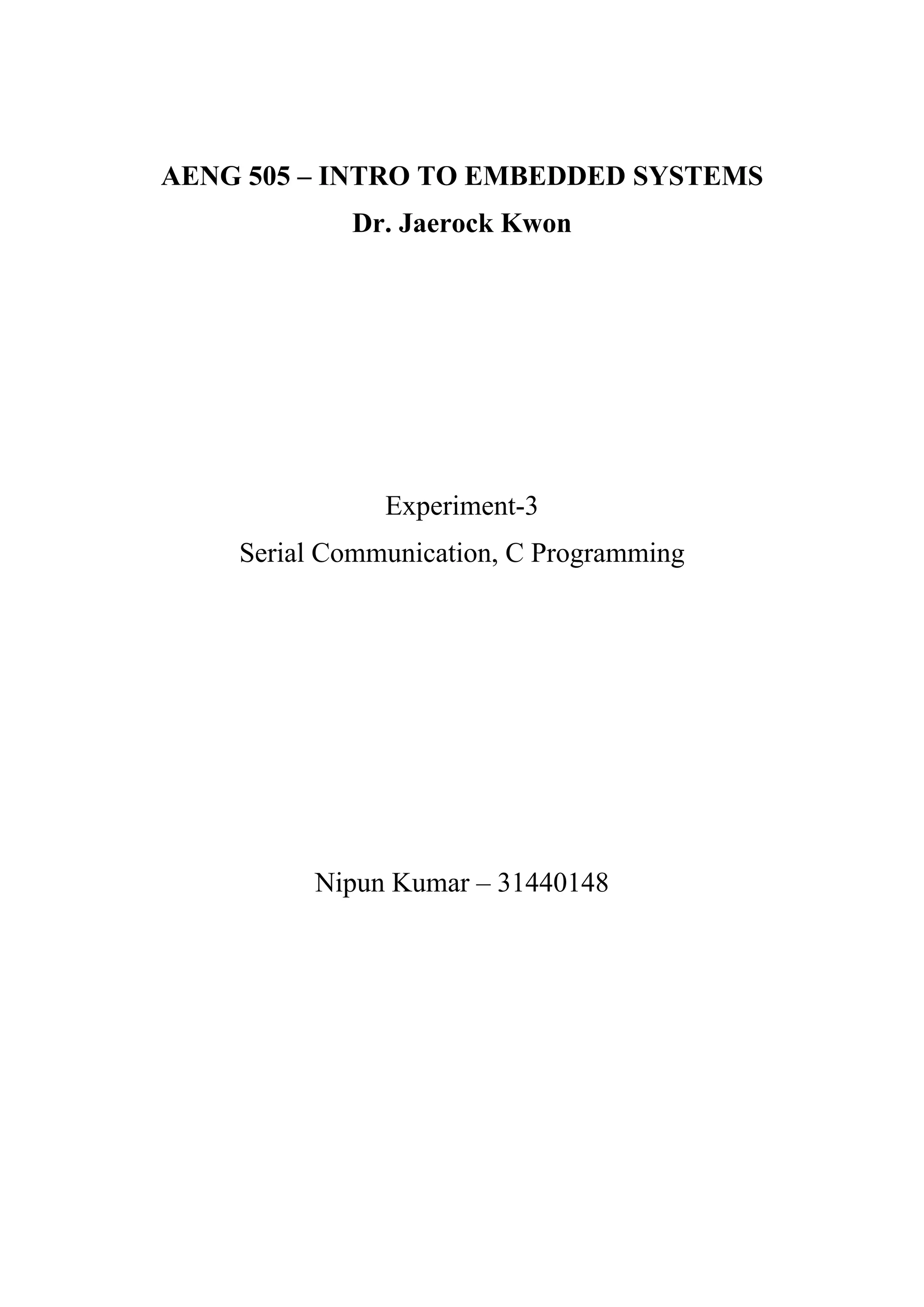
![Q4) Discuss how the compiled assembly code compares to the code written in C? How
many assembly instructions does the conversion from Celsius to Fahrenheit require?
Ans:
Below is the assembly code written by the compiler for the function convertToFahrenheit():
• Since assembly code uses registers to perform any kind of arithmetic operation,
compiler dedicates certain registers in this case, r0,r1,r2,r3,LR by saving their
previous values into stack pointer.
• TempC value is saved initially loaded into r0 register from [r13] address.
• After calculating the value of TempF, its value is saved into address [r13+4] for
usage.
• At the end r1,r2,r3 register values were restored from stack pointer for usage. LR
location is saved into PC for continuation of program.
Total 14 lines of assembly code (excluding the code inside labels) is written by the compiler
for the function convertToFahrenheit().
Conclusion:
• Communicating the data from and to Micro controller with the help of terminal
window and UART ports is understood.
• Simplification of port initialization is done with the help of library functions inside
TivaWare.
• Understood the difference in programming codes between assembly language and
any high-level language to perform the same functionality with micro controller.](https://image.slidesharecdn.com/exp-3report-221025181405-892c5608/85/C-programming-of-an-ARM-microcontroller-and-writing-UART-serial-communication-protocol-6-320.jpg)