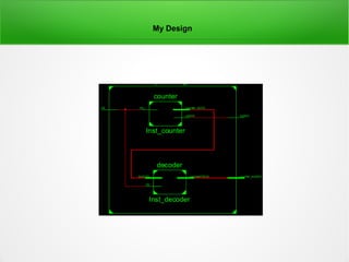
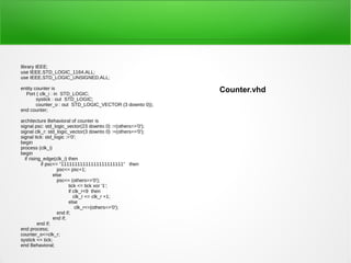
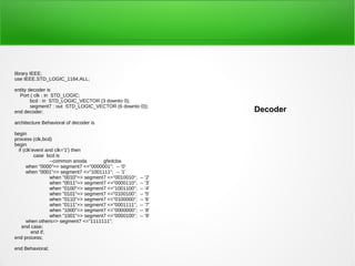
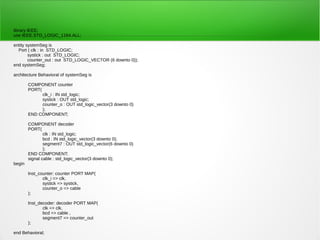
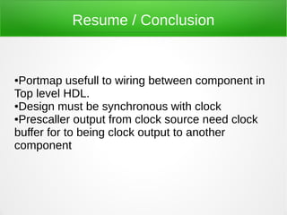
FPGA
Counter Seven Segment


              Created by
              Akhmad Hendriawan
              hendri@eepis-its.edu
You are free:
to Share — to copy, distribute and transmit the work
Under the following conditions:
Attribution — You must attribute the work in the manner specified by the author
or licensor (but not in any way that suggests that they endorse you or your use
of the work).
Noncommercial — You may not use this work for commercial purposes.
No Derivative Works — You may not alter, transform, or build upon this work.
Background


I try implement counter seven segmen in FPGA
●
Problem and solution

Problem:
First I don't know how to combine counter and decoder in HDL top level.
Usualy for my previous project , I do combining design with TOP level
schematic.

Solution:
I learn about portmap syntax for wiring component in HDL top level
My Design
library IEEE;
use IEEE.STD_LOGIC_1164.ALL;
use IEEE.STD_LOGIC_UNSIGNED.ALL;

entity counter is
  Port ( clk_i : in STD_LOGIC;
                                                              Counter.vhd
        systick : out STD_LOGIC;
        counter_o : out STD_LOGIC_VECTOR (3 downto 0));
end counter;

architecture Behavioral of counter is
signal psc: std_logic_vector(23 downto 0) :=(others=>'0');
signal clk_r: std_logic_vector(3 downto 0) :=(others=>'0');
signal tick: std_logic :='0';
begin
process (clk_i)
begin
  if rising_edge(clk_i) then
            if psc<= "11111111111111111111111" then
                    psc<= psc+1;
                  else
                    psc<= (others=>'0');
                          tick <= tick xor '1';
                          if clk_r<9 then
                             clk_r <= clk_r +1;
                          else
                              clk_r<=(others=>'0');
                    end if;
                  end if;
          end if;
end process;
counter_o<=clk_r;
systick <= tick;
end Behavioral;
library IEEE;
use IEEE.STD_LOGIC_1164.ALL;

entity decoder is
  Port ( clk : in STD_LOGIC;
        bcd : in STD_LOGIC_VECTOR (3 downto 0);
        segment7 : out STD_LOGIC_VECTOR (6 downto 0));
end decoder;                                                     Decoder
architecture Behavioral of decoder is

begin
process (clk,bcd)
begin
  if (clk'event and clk='1') then
           case bcd is
                  --common anoda       gfedcba
       when "0000"=> segment7 <="0000001"; -- '0'
       when "0001"=> segment7 <="1001111"; -- '1'
                  when "0010"=> segment7 <="0010010";   -- '2'
                  when "0011"=> segment7 <="0000110";   -- '3'
                  when "0100"=> segment7 <="1001100";   -- '4'
                  when "0101"=> segment7 <="0100100";   -- '5'
                  when "0110"=> segment7 <="0100000";   -- '6'
                  when "0111"=> segment7 <="0001111";   -- '7'
                  when "1000"=> segment7 <="0000000";   -- '8'
                  when "1001"=> segment7 <="0000100";   -- '9'
       when others=> segment7 <="1111111";
    end case;
         end if;
end process;

end Behavioral;
library IEEE;
use IEEE.STD_LOGIC_1164.ALL;

entity systemSeg is
  Port ( clk : in STD_LOGIC;
        systick : out STD_LOGIC;
        counter_out : out STD_LOGIC_VECTOR (6 downto 0));
end systemSeg;

architecture Behavioral of systemSeg is

        COMPONENT counter
        PORT(
              clk_i : IN std_logic;
              systick : OUT std_logic;
              counter_o : OUT std_logic_vector(3 downto 0)
              );
        END COMPONENT;

        COMPONENT decoder
        PORT(
                clk : IN std_logic;
                bcd : IN std_logic_vector(3 downto 0);
                segment7 : OUT std_logic_vector(6 downto 0)
                );
        END COMPONENT;
        signal cable : std_logic_vector(3 downto 0);
begin

        Inst_counter: counter PORT MAP(
               clk_i => clk,
               systick => systick,
               counter_o => cable
        );

        Inst_decoder: decoder PORT MAP(
               clk => clk,
               bcd => cable ,
               segment7 => counter_out
        );

end Behavioral;
Resume / Conclusion


●Portmap usefull to wiring between component in
Top level HDL.
●Design must be synchronous with clock

●Prescaller output from clock source need clock

buffer for to being clock output to another
component
Resume / Conclusion


●Portmap usefull to wiring between component in
Top level HDL.
●Design must be synchronous with clock

●Prescaller output from clock source need clock

buffer for to being clock output to another
component

Fpga creating counter with internal clock

  • 1.
    FPGA Counter Seven Segment Created by Akhmad Hendriawan hendri@eepis-its.edu
  • 2.
    You are free: toShare — to copy, distribute and transmit the work Under the following conditions: Attribution — You must attribute the work in the manner specified by the author or licensor (but not in any way that suggests that they endorse you or your use of the work). Noncommercial — You may not use this work for commercial purposes. No Derivative Works — You may not alter, transform, or build upon this work.
  • 3.
    Background I try implementcounter seven segmen in FPGA ●
  • 4.
    Problem and solution Problem: FirstI don't know how to combine counter and decoder in HDL top level. Usualy for my previous project , I do combining design with TOP level schematic. Solution: I learn about portmap syntax for wiring component in HDL top level
  • 5.
  • 6.
    library IEEE; use IEEE.STD_LOGIC_1164.ALL; useIEEE.STD_LOGIC_UNSIGNED.ALL; entity counter is Port ( clk_i : in STD_LOGIC; Counter.vhd systick : out STD_LOGIC; counter_o : out STD_LOGIC_VECTOR (3 downto 0)); end counter; architecture Behavioral of counter is signal psc: std_logic_vector(23 downto 0) :=(others=>'0'); signal clk_r: std_logic_vector(3 downto 0) :=(others=>'0'); signal tick: std_logic :='0'; begin process (clk_i) begin if rising_edge(clk_i) then if psc<= "11111111111111111111111" then psc<= psc+1; else psc<= (others=>'0'); tick <= tick xor '1'; if clk_r<9 then clk_r <= clk_r +1; else clk_r<=(others=>'0'); end if; end if; end if; end process; counter_o<=clk_r; systick <= tick; end Behavioral;
  • 7.
    library IEEE; use IEEE.STD_LOGIC_1164.ALL; entitydecoder is Port ( clk : in STD_LOGIC; bcd : in STD_LOGIC_VECTOR (3 downto 0); segment7 : out STD_LOGIC_VECTOR (6 downto 0)); end decoder; Decoder architecture Behavioral of decoder is begin process (clk,bcd) begin if (clk'event and clk='1') then case bcd is --common anoda gfedcba when "0000"=> segment7 <="0000001"; -- '0' when "0001"=> segment7 <="1001111"; -- '1' when "0010"=> segment7 <="0010010"; -- '2' when "0011"=> segment7 <="0000110"; -- '3' when "0100"=> segment7 <="1001100"; -- '4' when "0101"=> segment7 <="0100100"; -- '5' when "0110"=> segment7 <="0100000"; -- '6' when "0111"=> segment7 <="0001111"; -- '7' when "1000"=> segment7 <="0000000"; -- '8' when "1001"=> segment7 <="0000100"; -- '9' when others=> segment7 <="1111111"; end case; end if; end process; end Behavioral;
  • 8.
    library IEEE; use IEEE.STD_LOGIC_1164.ALL; entitysystemSeg is Port ( clk : in STD_LOGIC; systick : out STD_LOGIC; counter_out : out STD_LOGIC_VECTOR (6 downto 0)); end systemSeg; architecture Behavioral of systemSeg is COMPONENT counter PORT( clk_i : IN std_logic; systick : OUT std_logic; counter_o : OUT std_logic_vector(3 downto 0) ); END COMPONENT; COMPONENT decoder PORT( clk : IN std_logic; bcd : IN std_logic_vector(3 downto 0); segment7 : OUT std_logic_vector(6 downto 0) ); END COMPONENT; signal cable : std_logic_vector(3 downto 0); begin Inst_counter: counter PORT MAP( clk_i => clk, systick => systick, counter_o => cable ); Inst_decoder: decoder PORT MAP( clk => clk, bcd => cable , segment7 => counter_out ); end Behavioral;
  • 9.
    Resume / Conclusion ●Portmapusefull to wiring between component in Top level HDL. ●Design must be synchronous with clock ●Prescaller output from clock source need clock buffer for to being clock output to another component
  • 10.
    Resume / Conclusion ●Portmapusefull to wiring between component in Top level HDL. ●Design must be synchronous with clock ●Prescaller output from clock source need clock buffer for to being clock output to another component