Downloaded 16 times
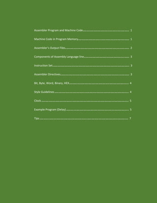
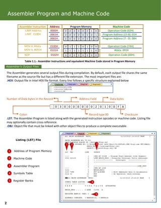
![Label: Assigns a symbolic representation to the address in program memory corresponding to line
Opcode: Reserved symbols that correspond to the operation to be performed by the microcontroller
Operands: Entities operated upon by the instruction
Comment: Used to document/understand programs
Components of Assembly Language line
Instruction Set
Assembler Directives
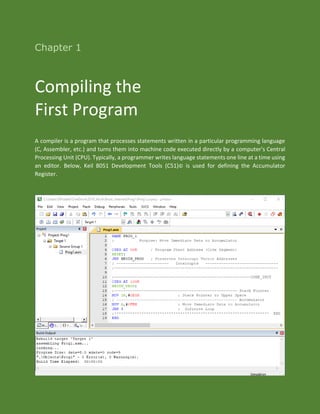
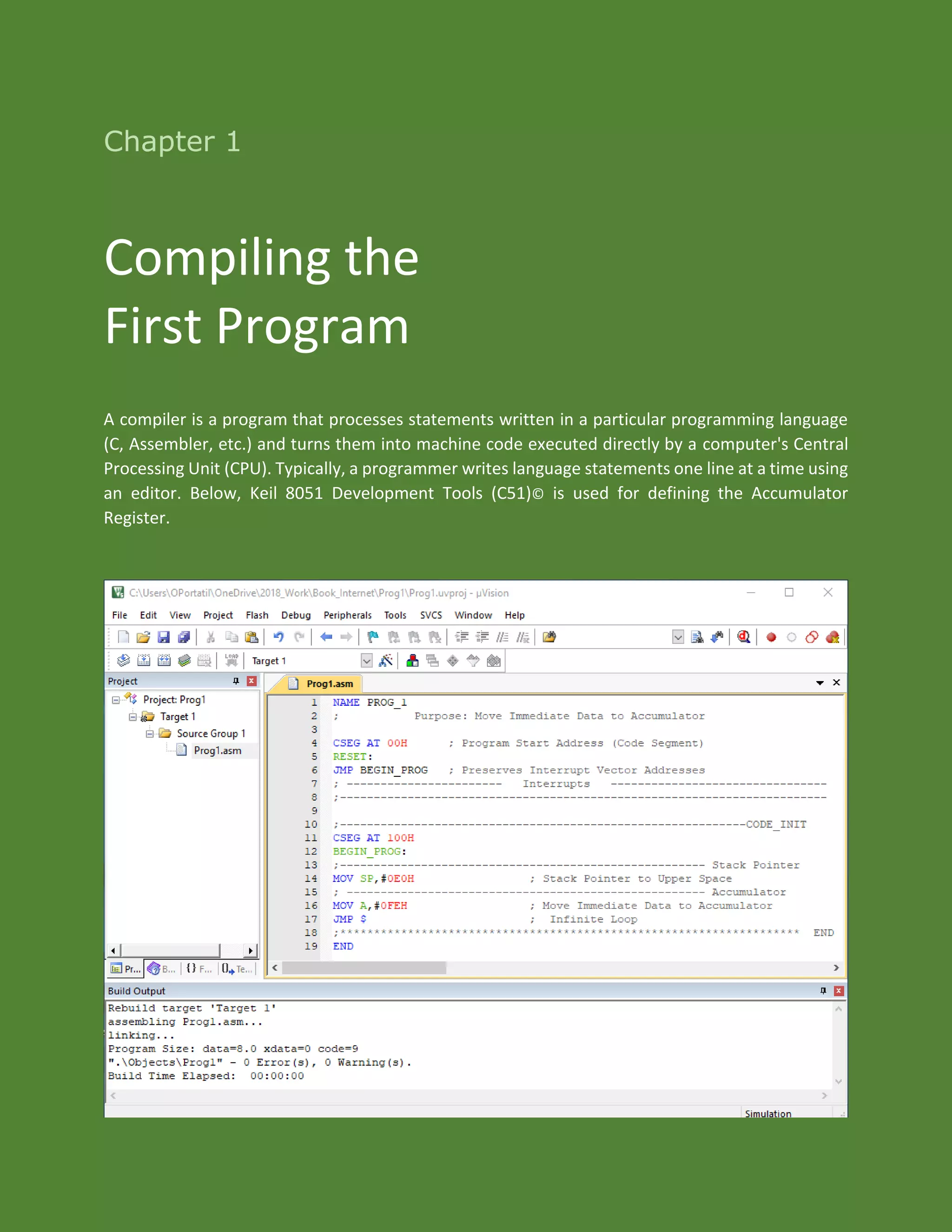
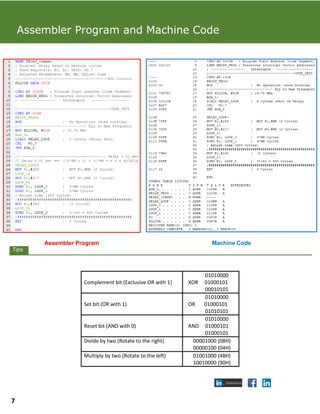
Assembler Program and Machine Code
Each line of assembly language source code has this general form:
{Label} {Opcode} {Operands} {;Comments}
1
2
3
4
11
2 2
33 4
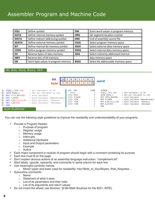
The Instruction Set of a Microprocessor executes at least the following general operations: Arithmetic and Logical, Data
Transfer, Boolean Variable Manipulation and Program Branching, some examples are shown in the following table
Arithmetic Operations Data Transfer Logical Operation Program Branching Boolean Variable
ADDC A,source MOV dest,#data ORL direct,A JNE @Ri,#data,rel SETB C
SUBB A,#data XCHD A,@Ri CPL A DJNZ Rn,rel CLR bit
DIV AB MOV DPTR, #data16 ANL A,#data LCALL addr16 JNB bit,rel
The operands involved in the instructions are described below
Rn Register addressing using R0-R7
direct 8 bit internal address (00H-FFH)
@Ri Indirect addressing using R0 or R1
source Any of [Rn,direct,@Ri]
dest Any of [Rn,direct,@Ri]
#data 8bit constant included in instruction
#data16 16bit constant included in instruction
bit 8bit direct address of bit
rel Signed 8bit offset
addr16 16bit address
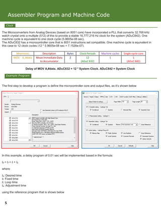
Directives are commands that are part of the assembler syntax but are not related to microcontroller instruction set.
Assembler Directives are used as instruction to the assembler and are no translated to machine code during the
assembly process. Some Instructions to Assembler: Address Control, Conditional Assembly, Memory Initialization and
Reservation, Procedure Declaration, Program Linkage, Symbol Definition, etc. The following table explains the actions
of certain directives
3](https://image.slidesharecdn.com/compilingfirstprogram-180117202327/85/Assembler-Programming-5-320.jpg)
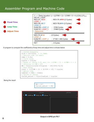

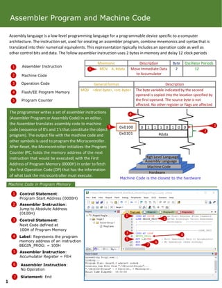
The document discusses an example assembly language program that implements a delay of 0.01 seconds using an 8051 microcontroller. It explains that the program uses nested loops and a subroutine to achieve the fixed, loop, and adjustment times needed for the desired delay. Registers R0 and R1 are used to control the loop counts. The program returns after completing all loops and the subroutine to produce the accurate 0.01 second delay.