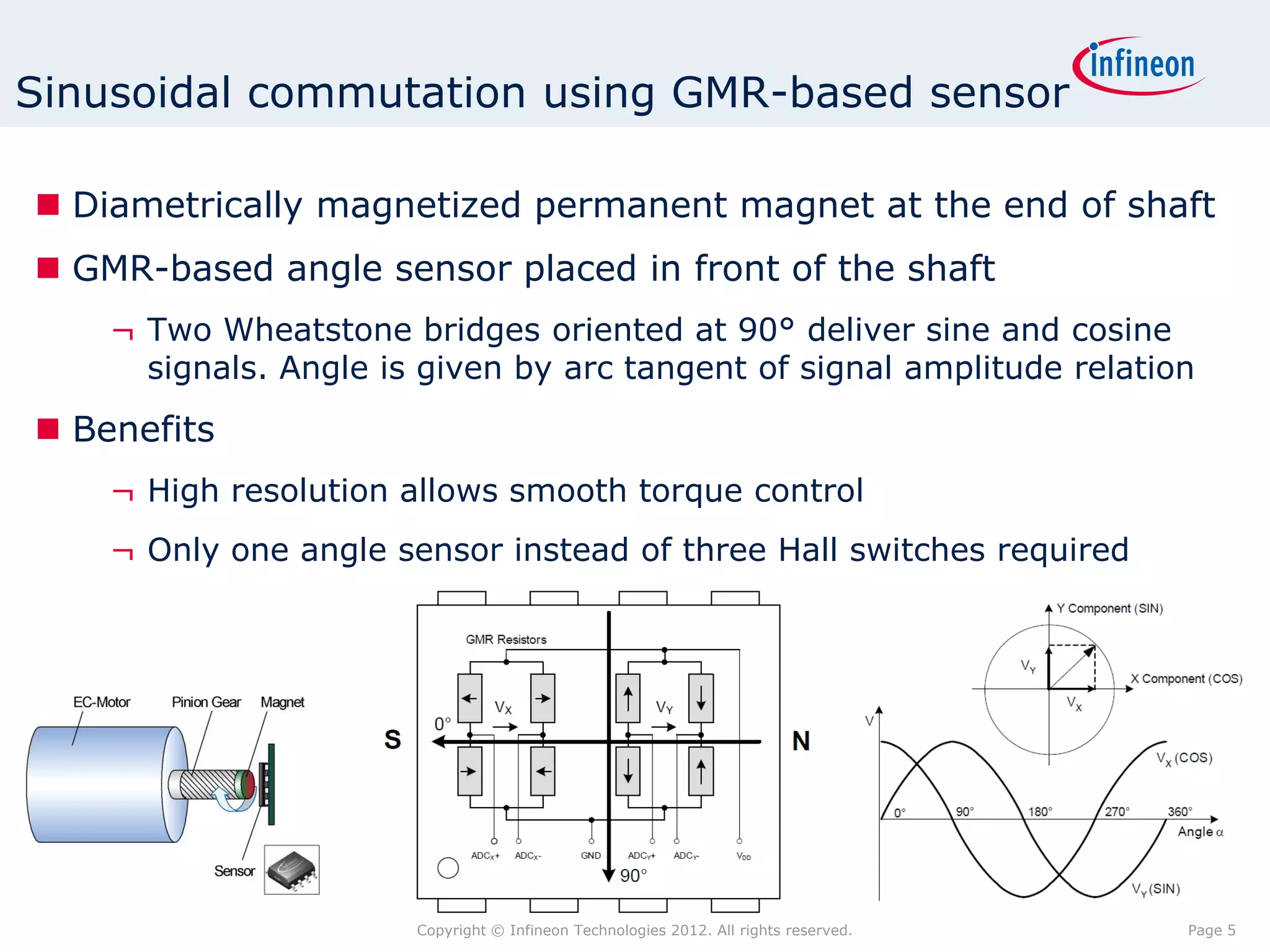
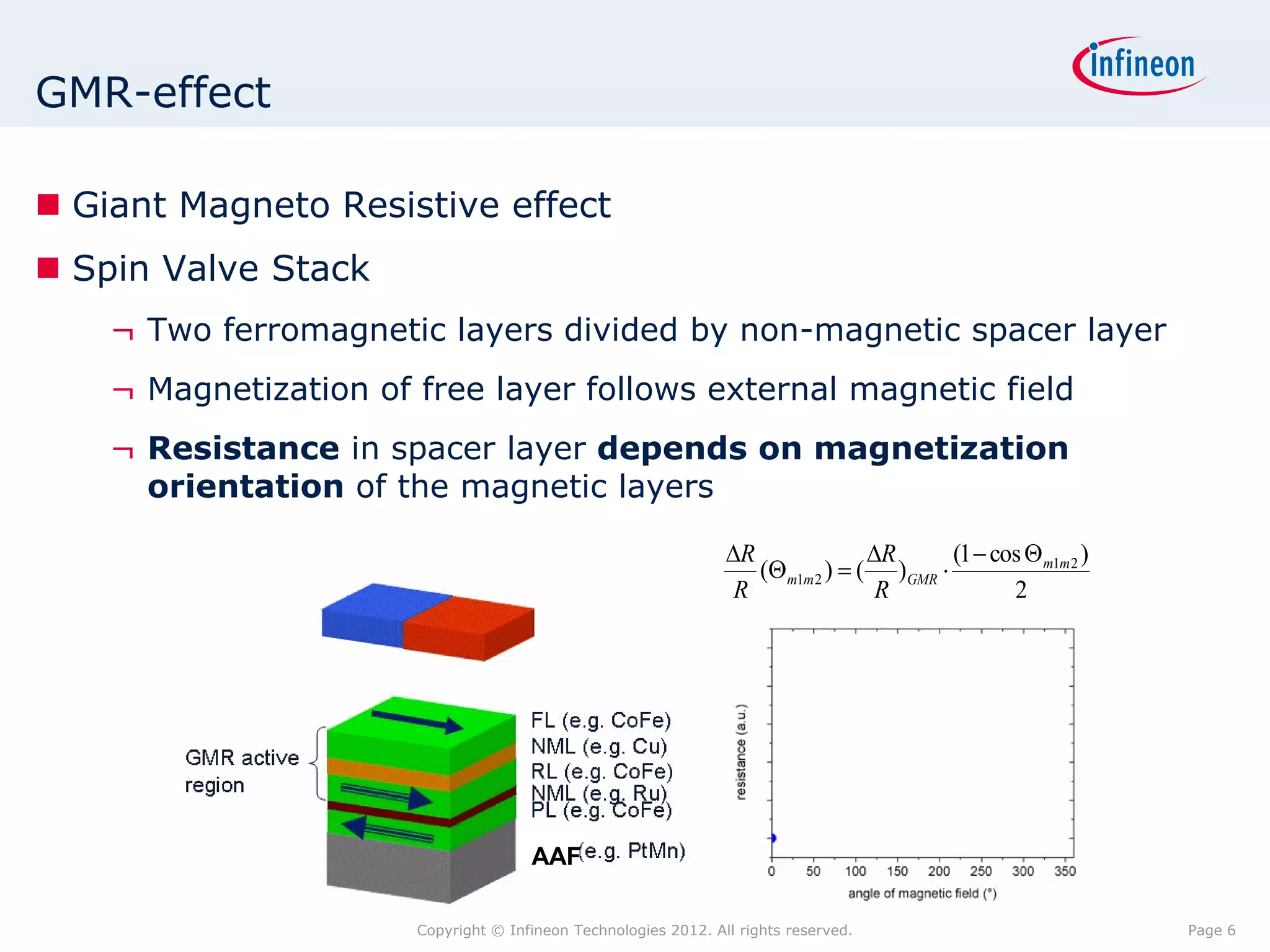
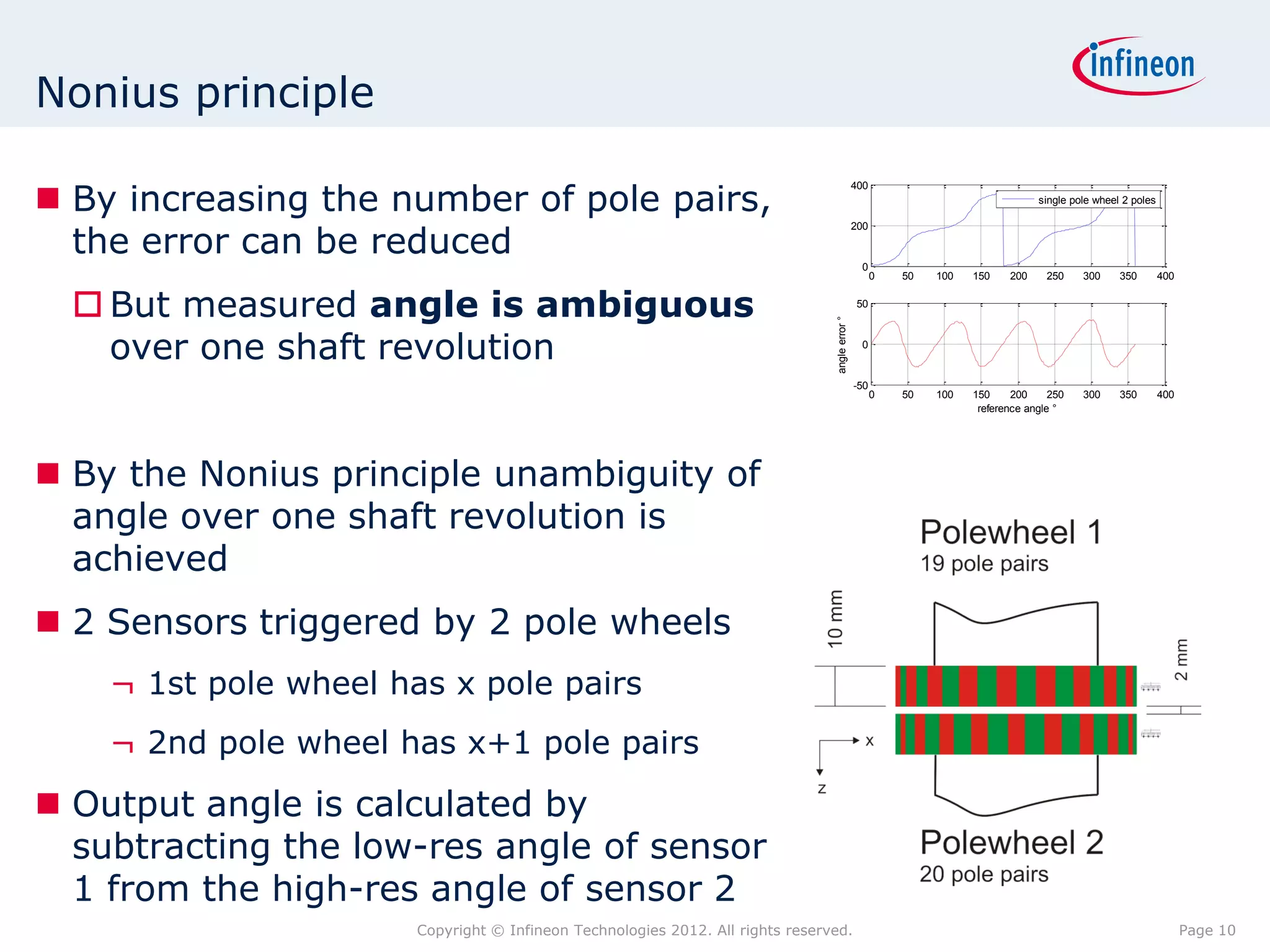
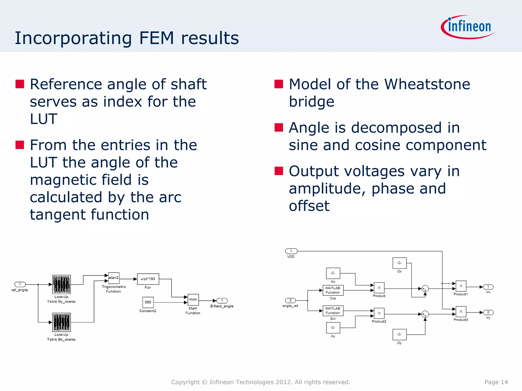
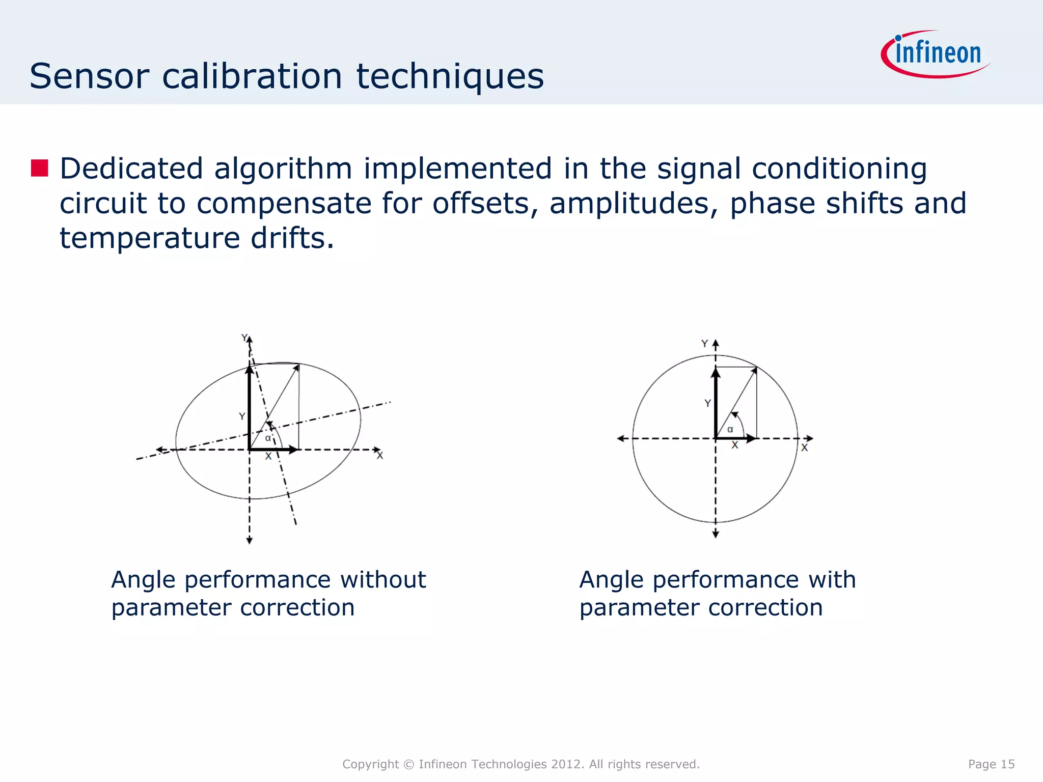
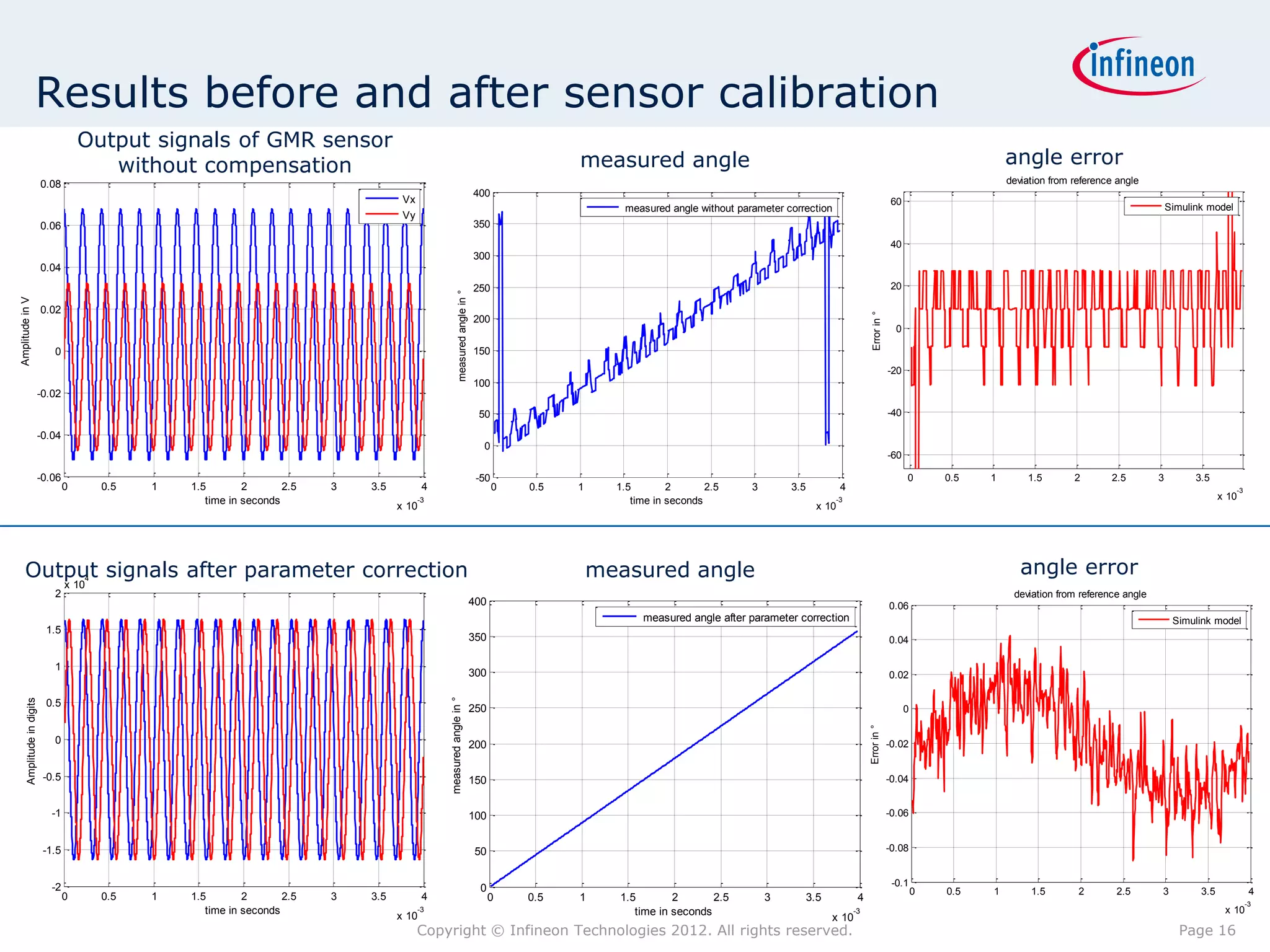
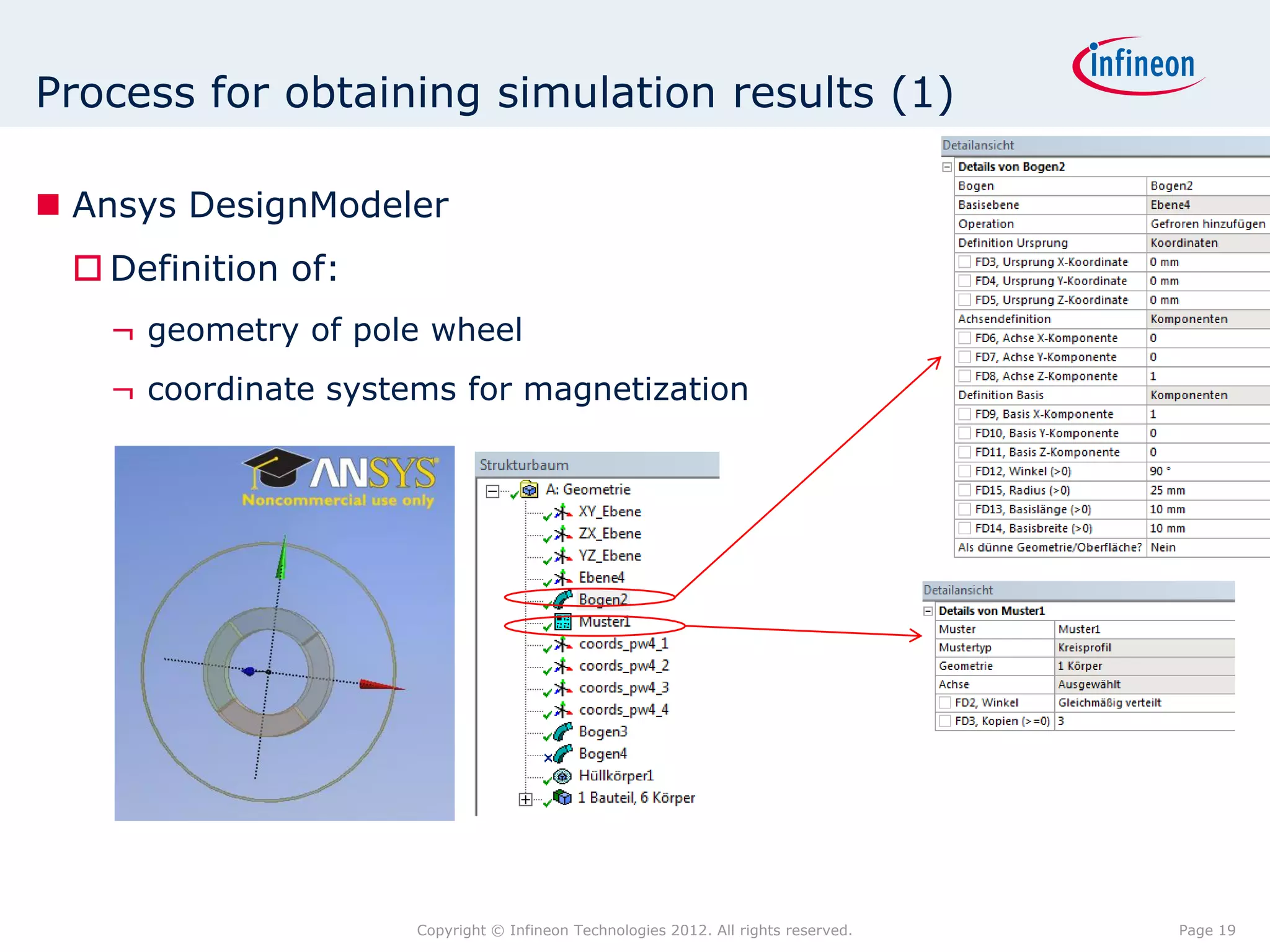
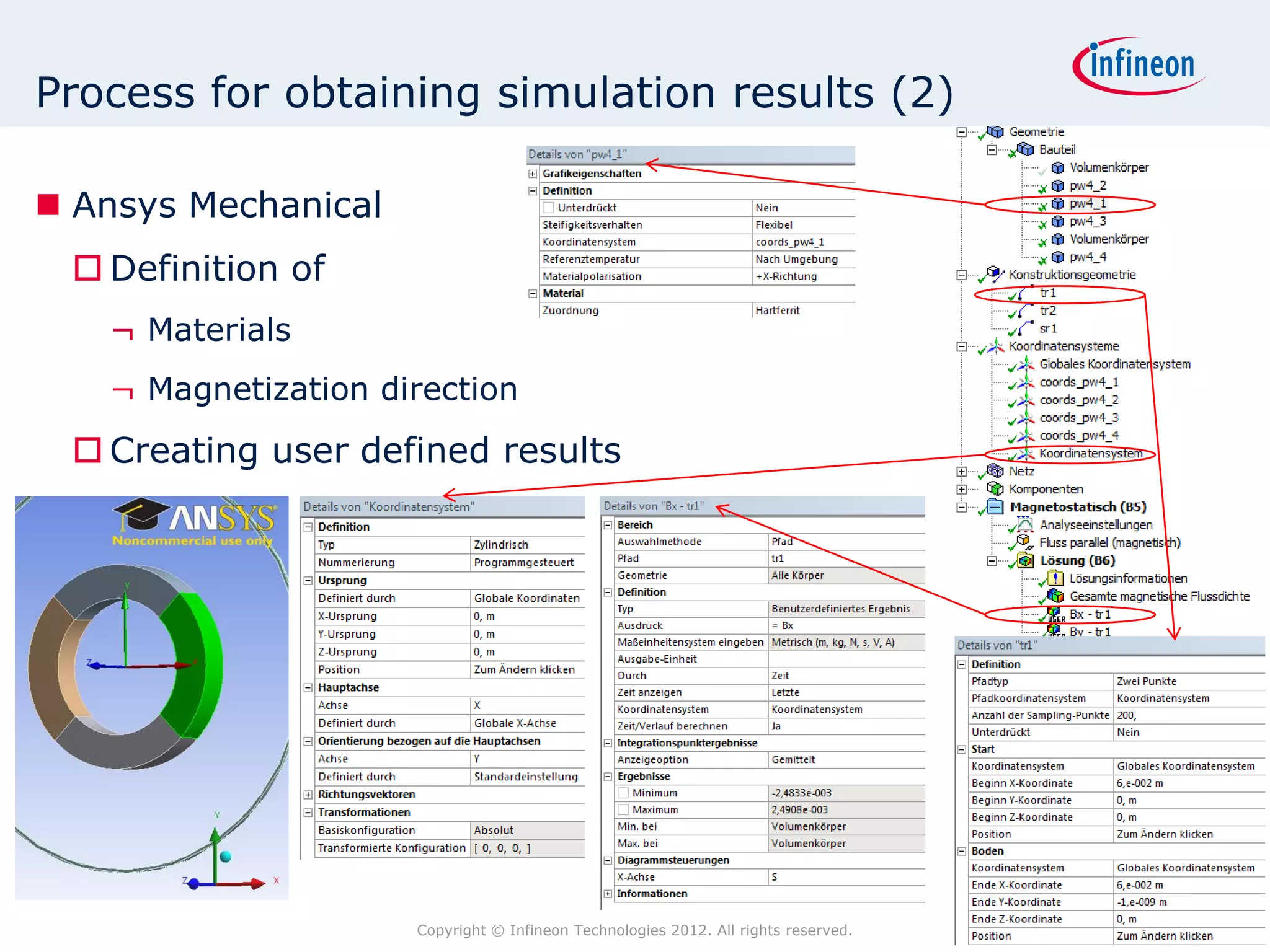
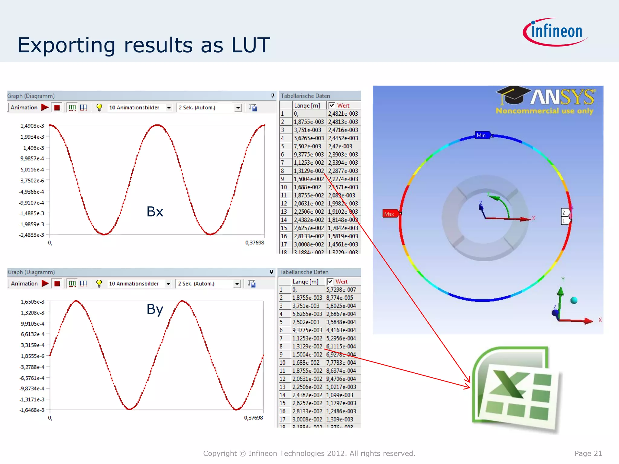
Simulation of a magnetic angle
measurement system
ANSYS Conference & 7. CADFEM Austria User‘s Meeting 26. – 27. April 2012


Gernot Binder
Outline

 Problem description
   Electrically commutated motor working principle
   Sinusoidal commutation
   Sinusoidal commutation using GMR angle sensor
   Out of axis angle measurement
 Magnetic circuit simulations
   Diametrically magnetized ring magnet
   Pole wheels with different number of pole pairs
   Nonius principle
 System simulations
   Incorporating FEM results in the MATLAB Simulink model
   Sensor Calibration
                         Copyright © Infineon Technologies 2012. All rights reserved.   Page 2
EC motor working principle

 Three excitation coils on stator
 Diametrically magnetized permanent
  magnet on rotor
 No mechanical contact between stator
  and rotor  brushless


 Benefits
    ¬ No mechanical wear
    ¬ small rotor inertia
 Drawbacks
    ¬ Need for a rotor/shaft position
      feedback system for current
      commutation
                       Copyright © Infineon Technologies 2012. All rights reserved.   Page 3
Sinusoidal commutation

 Three energized phases at a time
 Benefits of sinusoidal commutation:
   Low torque ripple
   high efficiency
 Rotor position has to be known with high accuracy

                                                                           3 excitation currents shifted by 120°
                                                                     1,2
                                                                       1
                                                                     0,8
                                                                     0,6
                                                    Phase current


                                                                     0,4
                                                                     0,2
                                                                       0                                           U
                                                                    -0,2
                                                                    -0,4                                           V
                                                                    -0,6
                                                                    -0,8                                           W
                                                                      -1
                                                                    -1,2
                                                                           0      100       200        300
                                                                                     reference angle


               Principle of a 3-phase driver stage and corresponding phase currents


                            Copyright © Infineon Technologies 2012. All rights reserved.                               Page 4
Sinusoidal commutation using GMR-based sensor

 Diametrically magnetized permanent magnet at the end of shaft
 GMR-based angle sensor placed in front of the shaft
    ¬ Two Wheatstone bridges oriented at 90° deliver sine and cosine
      signals. Angle is given by arc tangent of signal amplitude relation
 Benefits
    ¬ High resolution allows smooth torque control
    ¬ Only one angle sensor instead of three Hall switches required


                       Copyright © Infineon Technologies 2012. All rights reserved.   Page 5
GMR-effect

 Giant Magneto Resistive effect
 Spin Valve Stack
    ¬ Two ferromagnetic layers divided by non-magnetic spacer layer
    ¬ Magnetization of free layer follows external magnetic field
    ¬ Resistance in spacer layer depends on magnetization
      orientation of the magnetic layers

                                                                 R              R      (1  cos m1m 2 )
                                                                    (m1m 2 )  ( )GMR 
                                                                  R               R             2


                                      AAF

                       Copyright © Infineon Technologies 2012. All rights reserved.                          Page 6
Out of axis measurement

 End of shaft measurement not always possible
 Place sensor out of axis at the shaft circumference
 Problems occur:
   Angle accuracy depends on:
    ¬ Number of pole pairs / Magnetic coding
    ¬ Shaft diameter
    ¬ Sensor distance


 Use ANSYS to design a magnetic circuit that delivers
  appropriate magnetic fields
 Use Matlab/Simulink for a combined system simulation
  (Magnetic circuit – GMR sensor – Integrated signal
  conditioning)


                        Copyright © Infineon Technologies 2012. All rights reserved.   Page 7
Error sources

        ANSYS                                                                      Matlab / Simulink

  Geometry                                                                         Offsets
  Structure                                                                        Phase shifts
  Magnetization                                                                    Amplitudes
  Sensor location                                                                  Temperature drifts
                                                                                   Error compensation


                         Overall angle error


                    Magnetic
                                                          Sensor
                      circuit
                                                          related
                     related
                                                           errors
                      errors


                    Copyright © Infineon Technologies 2012. All rights reserved.                        Page 8
Magnetic analysis                                                                                                                                                                               90
                                                                                                                                                                                                        0.02
                                                                                                                                                                                          120                  60                                         400
                                                          0.02


                                                                                                                                                                                                                                       measured angle °
                                                                                                                                                              Bx                                       0.015                                              300
                                                  0.015                                                                                                       By
                                                                                                                                                                                                      0.01                                                200
                                                                                                                                                                                    150                              30
                                                          0.01
                                                                                                                                                                                                                                                          100
      magnetic flux density in T

                                                                                                                                                                                                      0.005
                                                  0.005
                                                                                                                                                                                                                                                            0
                                                                                                                                                                                                                                                                 0   50   100   150      200      250    300     350     400
                                                                                0                                                                                             180                                          0                                                      reference angle °

                                                                                                                                                                                                                                                           0.1
                                                  -0.005
                                                                                                                                                                                                                                                          0.05


                                                                                                                                                                                                                               angle error °
                                                   -0.01
                                                                                                                                                                                    210                              330                                    0

                                                  -0.015
                                                                                                                                                                                                                                                      -0.05

                                                   -0.02                                                                                                                                  240                  300                                        -0.1
                                                                                    0           50        100     150      200       250      300     350          400                                                                                           0   50   100   150      200      250    300     350     400
                                                                                                                   reference angle in °                                                         270                                                                               reference angle °


                                                                                                                                                                                                90
                                                                                                                                                                                                        0.04
                                                          0.04
                                                                                                                                                                                          120                  60
                                                                                                                                                                                                                                                          400
                                                          0.03                                                                                                                                         0.03                                                                                        single pole wheel 2 poles

                                                          0.02                                                                                                                      150               0.02           30                                   200
                     magnetic flux density in T


                                                          0.01                                                                                                                                        0.01
                                                                                                                                                                                                                                                             0
                                                                                0                                                                                                                                                                                0   50   100    150      200      250     300     350         400
                                                                                                                                                                              180                                          0
                                                   -0.01                                                                                                                                                                                                   50


                                                                                                                                                                                                                                     angle error °
                                                   -0.02

                                                                                                                                                                                    210                              330                                     0
                                                   -0.03


                                                   -0.04                                                                                                                                                                                                  -50
                                                                                    0           50        100     150      200       250      300     350          400                    240                  300                                               0   50   100    150     200     250       300     350         400
                                                                                                                   reference angle in °
                                                                                                                                                                                                270                                                                               reference angle °

                                                                                                                                                                                                90
                                                                                                                                                                                                        0.04
                                                                                0.04
                                                                                                                                                                                          120                  60                                         400
                                                                                                                                                                   Bx
                                                                                0.03                                                                               By                                  0.03                                                                                      single pole wheel 2 poles

                                                                                0.02                                                                                                150               0.02           30                                   200
                                                   magnetic flux density in T


                                                                                0.01                                                                                                                  0.01
                                                                                                                                                                                                                                                            0
                                                                                                                                                                                                                                                                 0   50   100    150      200      250     300     350         400
                                                                                        0
                                                                                                                                                                              180                                          0
                                                                                                                                                                                                                                                           50
                                                                                -0.01


                                                                                                                                                                                                                                 angle error °
                                                                                -0.02
                                                                                                                                                                                                                                                            0
                                                                                                                                                                                    210                              330
                                                                                -0.03

                                                                                                                                                                                                                                                          -50
                                                                                -0.04                                                                                                     240                  300                                               0   50   100    150     200     250       300     350         400
                                                                                            0        50     100      150      200       250     300     350             400
                                                                                                                      reference angle in °
                                                                                                                                                                                                                                                                                  reference angle °
                                                                                                                                                                                                270
                                                                                                                                              Copyright © Infineon Technologies 2012. All rights reserved.                                                                                                                           Page 9
Nonius principle

 By increasing the number of pole pairs,
                                                                                                400
                                                                                                                                  single pole wheel 2 poles


  the error can be reduced
                                                                                                200


                                                                                                 0
                                                                                                      0   50   100   150    200     250    300     350        400


   But measured angle is ambiguous                                                             50


                                                                                angle error °
    over one shaft revolution                                                                    0


                                                                                                -50
                                                                                                      0   50   100   150     200     250   300     350        400
                                                                                                                      reference angle °


 By the Nonius principle unambiguity of
  angle over one shaft revolution is
  achieved
 2 Sensors triggered by 2 pole wheels
    ¬ 1st pole wheel has x pole pairs
    ¬ 2nd pole wheel has x+1 pole pairs
 Output angle is calculated by
  subtracting the low-res angle of sensor
  1 from the high-res angle of sensor 2
                       Copyright © Infineon Technologies 2012. All rights reserved.                                                                                 Page 10
Result of the Nonius principle

 Maximum angle error is about +/- 0.07° (ideal magnetization)

                             400
          measured angle °


                             300

                             200
                                                                                    40 poles
                             100                                                    38 poles
                                                                                    output angle
                               0
                                    0   50   100   150      200       250     300      350         400
                                                     reference angle °


                              0.1
                                                                                     angle error
                             0.05
  angle error °


                               0

                         -0.05

                             -0.1
                                    0   50   100   150      200       250     300      350         400
                                                     reference angle °


                                                              Copyright © Infineon Technologies 2012. All rights reserved.   Page 11
Design optimization

 How large is the influence of non-ideal magnetization?
   Non-ideal magnetization: slightly varying pole widths
                      ¬ Production related alternating width of adjacent poles (+/- 2.2 %)
   Error increases to +/- 0.16°
                      400
   measured angle °


                      300

                      200
                                                                            40 poles
                      100                                                   38 poles
                                                                            output angle
                        0
                             0   50   100   150      200       250    300      350         400
                                              reference angle °

                      0.2
                                                                             angle error
                      0.1
  angle error °


                        0

                      -0.1

                      -0.2
                             0   50   100   150      200       250    300      350         400
                                              reference angle °


                                                            Copyright © Infineon Technologies 2012. All rights reserved.   Page 12
MATLAB Simulink model

 Influence of sensor electronics and signal processing is modeled
  using MATLAB Simulink
 B-field components obtained from FEM simulations are exported
  as *.txt-file

     Magnetic Circuit                      Sensor Related Errors                         Overall
      Related Errors                                                                   Angle Error


                        Copyright © Infineon Technologies 2012. All rights reserved.             Page 13
Incorporating FEM results

 Reference angle of shaft                              Model of the Wheatstone
  serves as index for the                                bridge
  LUT
                                                        Angle is decomposed in
 From the entries in the                                sine and cosine component
  LUT the angle of the
                                                        Output voltages vary in
  magnetic field is
                                                         amplitude, phase and
  calculated by the arc
                                                         offset
  tangent function


                     Copyright © Infineon Technologies 2012. All rights reserved.   Page 14
Sensor calibration techniques

 Dedicated algorithm implemented in the signal conditioning
  circuit to compensate for offsets, amplitudes, phase shifts and
  temperature drifts.


     Angle performance without                                Angle performance with
     parameter correction                                     parameter correction


                       Copyright © Infineon Technologies 2012. All rights reserved.    Page 15
Results before and after sensor calibration
                                          Output signals of GMR sensor
                                             without compensation                                                                                      measured angle                                                                                        angle error
                              0.08                                                                                                                                                                                                                           deviation from reference angle
                                                                                                                                      400
                                                                                            Vx                                                                                                                                        60
                                                                                                                                                              measured angle without parameter correction                                                                                          Simulink model
                                                                                            Vy
                              0.06                                                                                                    350
                                                                                                                                                                                                                                      40
                                                                                                                                      300
                              0.04
                                                                                                                                      250                                                                                             20


                                                                                                                measured angle in °
Amplitude in V


                              0.02


                                                                                                                                                                                                                        Error in °
                                                                                                                                      200
                                                                                                                                                                                                                                       0

                                 0                                                                                                    150
                                                                                                                                                                                                                                     -20
                                                                                                                                      100
                              -0.02
                                                                                                                                       50                                                                                            -40

                              -0.04
                                                                                                                                        0
                                                                                                                                                                                                                                     -60

                              -0.06                                                                                                    -50                                                                                                 0       0.5   1       1.5        2       2.5        3         3.5
                                      0       0.5   1   1.5        2       2.5   3   3.5          4                                          0   0.5   1     1.5        2       2.5     3       3.5           4                                                                                                     -3
                                                           time in seconds                       -3                                                             time in seconds                             -3                                                                                                  x 10
                                                                                           x 10                                                                                                        x 10


     Output signals after parameter correction
                                          4                                                                                                                measured angle                                                                                       angle error
                                      x 10
                                 2                                                                                                                                                                                                                            deviation from reference angle
                                                                                                                                      400                                                                                            0.06
                                                                                                                                                                  measured angle after parameter correction                                                                                         Simulink model
                               1.5
                                                                                                                                      350                                                                                            0.04

                                 1
                                                                                                                                      300                                                                                            0.02
                                                                                                      measured angle in °
        Amplitude in digits


                               0.5
                                                                                                                                      250                                                                                                  0


                                                                                                                                                                                                                       Error in °
                                 0                                                                                                    200                                                                                            -0.02


                               -0.5                                                                                                   150                                                                                            -0.04


                                 -1                                                                                                   100                                                                                            -0.06


                               -1.5                                                                                                   50                                                                                             -0.08


                                 -2                                                                                                                                                                                                   -0.1
                                                                                                                                       0                                                                                                       0   0.5   1        1.5        2       2.5       3          3.5             4
                                      0       0.5   1   1.5        2       2.5   3   3.5          4                                         0    0.5   1     1.5        2       2.5         3         3.5          4
                                                                                                                                                                                                                                                                                                                         -3
                                                           time in seconds                       -3                                                             time in seconds                                   -3                                                                                             x 10
                                                                                           x 10                                                                                                             x 10
                                                                                                 Copyright © Infineon Technologies 2012. All rights reserved.                                                                                                                                        Page 16
Thank you for your attention!

 References

  Infineon Technologies AG. Position Feedback for Motor Control Using Magnetic Sensors. Infineon
   Technologies AG, 2010.

  Infineon Technologies AG. TLE5012B GMR-Based Angular Sensor - Datasheet. Infineon Technologies
   AG, 2010.

  Infineon Technologies AG. TLE5009 GMR-Based Angular Sensor - Application Note TLE5009
   Calibration. Infineon Technologies AG, 2010.


                              Copyright © Infineon Technologies 2012. All rights reserved.      Page 17
Appendix
Process for obtaining simulation results (1)

 Ansys DesignModeler
  Definition of:
   ¬ geometry of pole wheel
   ¬ coordinate systems for magnetization


                     Copyright © Infineon Technologies 2012. All rights reserved.   Page 19
Process for obtaining simulation results (2)

 Ansys Mechanical
  Definition of
   ¬ Materials
   ¬ Magnetization direction
  Creating user defined results


                     Copyright © Infineon Technologies 2012. All rights reserved.   Page 20
Exporting results as LUT


            Bx


            By


                 Copyright © Infineon Technologies 2012. All rights reserved.   Page 21
Fragen? Interesse?

Kontaktieren Sie uns – wir helfen Ihnen gerne!
CADFEM (Austria) GmbH
Wagenseilgasse 14
1120 Wien
Tel. +43 (0)1 587 70 73 – 0
E-Mail. info@cadfem.at
Web. http://www.cadfem.at

Immer aktuell informiert – CADFEM Blog, Xing und Youtube-
Channel
CADFEM Blog - Umfassend informiert
               •   News zur FEM-Simulation - What‘s hot? What‘s new?
               •   Video-Tutorials - ANSYS, LS DYNA & mehr
               •   Hinter den Kulissen: CADFEM intern

CADFEM Youtube Channel - Tips & Trick
               •   Video Tutorials - ANSYS Software und CADFEM Applications


CADFEM auf Xing - News kompakt
               •   Vorschau auf Events & Seminare
               •   Neue CADFEM Produkte
               •   CADFEM Jobbörse
Fragen? Interesse?

Kontaktieren Sie uns – wir helfen Ihnen gerne!
CADFEM (Austria) GmbH
Wagenseilgasse 14
1120 Wien
Tel. +43 (0)1 587 70 73 – 0
E-Mail. info@cadfem.at
Web. http://www.cadfem.at


Immer aktuell informiert – CADFEM Blog, Xing und Youtube-Channel
CADFEM Blog - Umfassend informiert
                              •   News zur FEM-Simulation - What‘s hot? What‘s new?
                              •   Video-Tutorials - ANSYS, LS DYNA & mehr
                              •   Hinter den Kulissen: CADFEM intern


CADFEM Youtube Channel - Tips & Trick
                              •   Video Tutorials - ANSYS Software und CADFEM Applications


CADFEM auf Xing - News kompakt
                              •   Vorschau auf Events & Seminare
                              •   Neue CADFEM Produkte
                              •   CADFEM Jobbörse

ANSYS: Simulation of a magnetic angle measurement system

  • 1.
    Simulation of amagnetic angle measurement system ANSYS Conference & 7. CADFEM Austria User‘s Meeting 26. – 27. April 2012 Gernot Binder
  • 2.
    Outline  Problem description  Electrically commutated motor working principle  Sinusoidal commutation  Sinusoidal commutation using GMR angle sensor  Out of axis angle measurement  Magnetic circuit simulations  Diametrically magnetized ring magnet  Pole wheels with different number of pole pairs  Nonius principle  System simulations  Incorporating FEM results in the MATLAB Simulink model  Sensor Calibration Copyright © Infineon Technologies 2012. All rights reserved. Page 2
  • 3.
    EC motor workingprinciple  Three excitation coils on stator  Diametrically magnetized permanent magnet on rotor  No mechanical contact between stator and rotor  brushless  Benefits ¬ No mechanical wear ¬ small rotor inertia  Drawbacks ¬ Need for a rotor/shaft position feedback system for current commutation Copyright © Infineon Technologies 2012. All rights reserved. Page 3
  • 4.
    Sinusoidal commutation  Threeenergized phases at a time  Benefits of sinusoidal commutation:  Low torque ripple  high efficiency  Rotor position has to be known with high accuracy 3 excitation currents shifted by 120° 1,2 1 0,8 0,6 Phase current 0,4 0,2 0 U -0,2 -0,4 V -0,6 -0,8 W -1 -1,2 0 100 200 300 reference angle Principle of a 3-phase driver stage and corresponding phase currents Copyright © Infineon Technologies 2012. All rights reserved. Page 4
  • 5.
    Sinusoidal commutation usingGMR-based sensor  Diametrically magnetized permanent magnet at the end of shaft  GMR-based angle sensor placed in front of the shaft ¬ Two Wheatstone bridges oriented at 90° deliver sine and cosine signals. Angle is given by arc tangent of signal amplitude relation  Benefits ¬ High resolution allows smooth torque control ¬ Only one angle sensor instead of three Hall switches required Copyright © Infineon Technologies 2012. All rights reserved. Page 5
  • 6.
    GMR-effect  Giant MagnetoResistive effect  Spin Valve Stack ¬ Two ferromagnetic layers divided by non-magnetic spacer layer ¬ Magnetization of free layer follows external magnetic field ¬ Resistance in spacer layer depends on magnetization orientation of the magnetic layers R R (1  cos m1m 2 ) (m1m 2 )  ( )GMR  R R 2 AAF Copyright © Infineon Technologies 2012. All rights reserved. Page 6
  • 7.
    Out of axismeasurement  End of shaft measurement not always possible  Place sensor out of axis at the shaft circumference  Problems occur:  Angle accuracy depends on: ¬ Number of pole pairs / Magnetic coding ¬ Shaft diameter ¬ Sensor distance  Use ANSYS to design a magnetic circuit that delivers appropriate magnetic fields  Use Matlab/Simulink for a combined system simulation (Magnetic circuit – GMR sensor – Integrated signal conditioning) Copyright © Infineon Technologies 2012. All rights reserved. Page 7
  • 8.
    Error sources ANSYS Matlab / Simulink Geometry Offsets Structure Phase shifts Magnetization Amplitudes Sensor location Temperature drifts Error compensation Overall angle error Magnetic Sensor circuit related related errors errors Copyright © Infineon Technologies 2012. All rights reserved. Page 8
  • 9.
    Magnetic analysis 90 0.02 120 60 400 0.02 measured angle ° Bx 0.015 300 0.015 By 0.01 200 150 30 0.01 100 magnetic flux density in T 0.005 0.005 0 0 50 100 150 200 250 300 350 400 0 180 0 reference angle ° 0.1 -0.005 0.05 angle error ° -0.01 210 330 0 -0.015 -0.05 -0.02 240 300 -0.1 0 50 100 150 200 250 300 350 400 0 50 100 150 200 250 300 350 400 reference angle in ° 270 reference angle ° 90 0.04 0.04 120 60 400 0.03 0.03 single pole wheel 2 poles 0.02 150 0.02 30 200 magnetic flux density in T 0.01 0.01 0 0 0 50 100 150 200 250 300 350 400 180 0 -0.01 50 angle error ° -0.02 210 330 0 -0.03 -0.04 -50 0 50 100 150 200 250 300 350 400 240 300 0 50 100 150 200 250 300 350 400 reference angle in ° 270 reference angle ° 90 0.04 0.04 120 60 400 Bx 0.03 By 0.03 single pole wheel 2 poles 0.02 150 0.02 30 200 magnetic flux density in T 0.01 0.01 0 0 50 100 150 200 250 300 350 400 0 180 0 50 -0.01 angle error ° -0.02 0 210 330 -0.03 -50 -0.04 240 300 0 50 100 150 200 250 300 350 400 0 50 100 150 200 250 300 350 400 reference angle in ° reference angle ° 270 Copyright © Infineon Technologies 2012. All rights reserved. Page 9
  • 10.
    Nonius principle  Byincreasing the number of pole pairs, 400 single pole wheel 2 poles the error can be reduced 200 0 0 50 100 150 200 250 300 350 400  But measured angle is ambiguous 50 angle error ° over one shaft revolution 0 -50 0 50 100 150 200 250 300 350 400 reference angle °  By the Nonius principle unambiguity of angle over one shaft revolution is achieved  2 Sensors triggered by 2 pole wheels ¬ 1st pole wheel has x pole pairs ¬ 2nd pole wheel has x+1 pole pairs  Output angle is calculated by subtracting the low-res angle of sensor 1 from the high-res angle of sensor 2 Copyright © Infineon Technologies 2012. All rights reserved. Page 10
  • 11.
    Result of theNonius principle  Maximum angle error is about +/- 0.07° (ideal magnetization) 400 measured angle ° 300 200 40 poles 100 38 poles output angle 0 0 50 100 150 200 250 300 350 400 reference angle ° 0.1 angle error 0.05 angle error ° 0 -0.05 -0.1 0 50 100 150 200 250 300 350 400 reference angle ° Copyright © Infineon Technologies 2012. All rights reserved. Page 11
  • 12.
    Design optimization  Howlarge is the influence of non-ideal magnetization?  Non-ideal magnetization: slightly varying pole widths ¬ Production related alternating width of adjacent poles (+/- 2.2 %)  Error increases to +/- 0.16° 400 measured angle ° 300 200 40 poles 100 38 poles output angle 0 0 50 100 150 200 250 300 350 400 reference angle ° 0.2 angle error 0.1 angle error ° 0 -0.1 -0.2 0 50 100 150 200 250 300 350 400 reference angle ° Copyright © Infineon Technologies 2012. All rights reserved. Page 12
  • 13.
    MATLAB Simulink model Influence of sensor electronics and signal processing is modeled using MATLAB Simulink  B-field components obtained from FEM simulations are exported as *.txt-file Magnetic Circuit Sensor Related Errors Overall Related Errors Angle Error Copyright © Infineon Technologies 2012. All rights reserved. Page 13
  • 14.
    Incorporating FEM results Reference angle of shaft  Model of the Wheatstone serves as index for the bridge LUT  Angle is decomposed in  From the entries in the sine and cosine component LUT the angle of the  Output voltages vary in magnetic field is amplitude, phase and calculated by the arc offset tangent function Copyright © Infineon Technologies 2012. All rights reserved. Page 14
  • 15.
    Sensor calibration techniques Dedicated algorithm implemented in the signal conditioning circuit to compensate for offsets, amplitudes, phase shifts and temperature drifts. Angle performance without Angle performance with parameter correction parameter correction Copyright © Infineon Technologies 2012. All rights reserved. Page 15
  • 16.
    Results before andafter sensor calibration Output signals of GMR sensor without compensation measured angle angle error 0.08 deviation from reference angle 400 Vx 60 measured angle without parameter correction Simulink model Vy 0.06 350 40 300 0.04 250 20 measured angle in ° Amplitude in V 0.02 Error in ° 200 0 0 150 -20 100 -0.02 50 -40 -0.04 0 -60 -0.06 -50 0 0.5 1 1.5 2 2.5 3 3.5 0 0.5 1 1.5 2 2.5 3 3.5 4 0 0.5 1 1.5 2 2.5 3 3.5 4 -3 time in seconds -3 time in seconds -3 x 10 x 10 x 10 Output signals after parameter correction 4 measured angle angle error x 10 2 deviation from reference angle 400 0.06 measured angle after parameter correction Simulink model 1.5 350 0.04 1 300 0.02 measured angle in ° Amplitude in digits 0.5 250 0 Error in ° 0 200 -0.02 -0.5 150 -0.04 -1 100 -0.06 -1.5 50 -0.08 -2 -0.1 0 0 0.5 1 1.5 2 2.5 3 3.5 4 0 0.5 1 1.5 2 2.5 3 3.5 4 0 0.5 1 1.5 2 2.5 3 3.5 4 -3 time in seconds -3 time in seconds -3 x 10 x 10 x 10 Copyright © Infineon Technologies 2012. All rights reserved. Page 16
  • 17.
    Thank you foryour attention!  References  Infineon Technologies AG. Position Feedback for Motor Control Using Magnetic Sensors. Infineon Technologies AG, 2010.  Infineon Technologies AG. TLE5012B GMR-Based Angular Sensor - Datasheet. Infineon Technologies AG, 2010.  Infineon Technologies AG. TLE5009 GMR-Based Angular Sensor - Application Note TLE5009 Calibration. Infineon Technologies AG, 2010. Copyright © Infineon Technologies 2012. All rights reserved. Page 17
  • 18.
  • 19.
    Process for obtainingsimulation results (1)  Ansys DesignModeler  Definition of: ¬ geometry of pole wheel ¬ coordinate systems for magnetization Copyright © Infineon Technologies 2012. All rights reserved. Page 19
  • 20.
    Process for obtainingsimulation results (2)  Ansys Mechanical  Definition of ¬ Materials ¬ Magnetization direction  Creating user defined results Copyright © Infineon Technologies 2012. All rights reserved. Page 20
  • 21.
    Exporting results asLUT Bx By Copyright © Infineon Technologies 2012. All rights reserved. Page 21
  • 23.
    Fragen? Interesse? Kontaktieren Sieuns – wir helfen Ihnen gerne! CADFEM (Austria) GmbH Wagenseilgasse 14 1120 Wien Tel. +43 (0)1 587 70 73 – 0 E-Mail. info@cadfem.at Web. http://www.cadfem.at Immer aktuell informiert – CADFEM Blog, Xing und Youtube- Channel CADFEM Blog - Umfassend informiert • News zur FEM-Simulation - What‘s hot? What‘s new? • Video-Tutorials - ANSYS, LS DYNA & mehr • Hinter den Kulissen: CADFEM intern CADFEM Youtube Channel - Tips & Trick • Video Tutorials - ANSYS Software und CADFEM Applications CADFEM auf Xing - News kompakt • Vorschau auf Events & Seminare • Neue CADFEM Produkte • CADFEM Jobbörse
  • 24.
    Fragen? Interesse? Kontaktieren Sieuns – wir helfen Ihnen gerne! CADFEM (Austria) GmbH Wagenseilgasse 14 1120 Wien Tel. +43 (0)1 587 70 73 – 0 E-Mail. info@cadfem.at Web. http://www.cadfem.at Immer aktuell informiert – CADFEM Blog, Xing und Youtube-Channel CADFEM Blog - Umfassend informiert • News zur FEM-Simulation - What‘s hot? What‘s new? • Video-Tutorials - ANSYS, LS DYNA & mehr • Hinter den Kulissen: CADFEM intern CADFEM Youtube Channel - Tips & Trick • Video Tutorials - ANSYS Software und CADFEM Applications CADFEM auf Xing - News kompakt • Vorschau auf Events & Seminare • Neue CADFEM Produkte • CADFEM Jobbörse