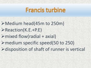
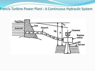
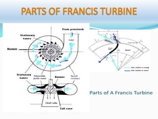
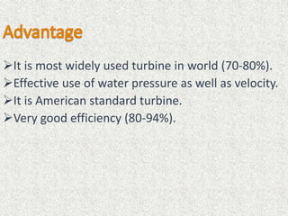
FRANCIS TURBINE
Submitted To :
Mr. PM Meena
(Professor)
Mechanical Engg. Dept.
MBM Engg. College Jodhpur
Submitted By :
Prashant Kumar Soni
Rajender Singh
Deepak Kumar Kakkad
Vinay Agarwal
(BE Final Year)
 Used for hydro electric power, i.e. cheapest
source of power generation.
 hydraulic energy mechanical energy
electrical energy
 power generating device
 Pelton wheel turbine
 Francis turbine
 Kaplan turbine
Head and quantity of water available
Hydraulic action of water
Direction of flow of water in the runner
Specific speed of turbines
Disposition of the shaft of the runner
Medium head(45m to 250m)
Reaction(K.E.+P.E)
mixed flow(radial + axial)
medium specific speed(50 to 250)
disposition of shaft of runner is vertical
Penstock-it is a large size conduit which conveys
water from upstream to the dam/reservoir to the
turbine runner
 spiral casing- it constitutes a closed passage
whose cross section area gradually decrease along
flow direction area is maximum at inlet and nearly
zero at exit
guide vanes-these vanes direct the water on the
runner at an angle appropriate to the design,
controlled by hand wheel or governor
Governing mechanism-it changes the position of
guide vanes to affect a variation in water flow rate,
when the load condition on the turbine changes
Runner and runner blades-the driving force on the
runner is both due to impulse and reaction
effect(usually runner blades 16-24).
Draft tube-it is generally an expending tube which
discharges the water, passing through the runner to
the tail race.
Hydraulic Efficiency - It is ratio of power developed by the runner of a
turbine to the power supplied by the water at the inlet.
ηh =
Power developed by the runner
Power available at the inlet
Mechanical Efficiency – It is ratio of power available at the shaft to power
developed at the runner.
ηm =
Power at the shaft of the turbine
Power developed by the runner
• Volumetric Efficiency - It is ratio of volume of the water actually striking
the runner to the volume of water supplied to the turbine.
• Volumetric efficiency ηv =
volume of water striking the bucket
volume of water supplied to the turbine
• Overall Efficiency - It is ratio of power available at the shaft of the
turbine to the power supplied by the water at the inlet of the turbine.
• Overall efficiency ηov =
Power available to the shaft
Power suppied at the inlet
Normal overall efficiency ηov = ηv ∙ ηm ∙ ηh
It is most widely used turbine in world (70-80%).
Effective use of water pressure as well as velocity.
It is American standard turbine.
Very good efficiency (80-94%).
Cost is high.
Due to it’s complex design and large no of moving
parts, maintenance and repair is difficult and costly.
It is applicable to flow of medium head only.

TURBINE-2

  • 1.
    FRANCIS TURBINE Submitted To: Mr. PM Meena (Professor) Mechanical Engg. Dept. MBM Engg. College Jodhpur Submitted By : Prashant Kumar Soni Rajender Singh Deepak Kumar Kakkad Vinay Agarwal (BE Final Year)
  • 2.
     Used forhydro electric power, i.e. cheapest source of power generation.  hydraulic energy mechanical energy electrical energy  power generating device
  • 3.
     Pelton wheelturbine  Francis turbine  Kaplan turbine
  • 4.
    Head and quantityof water available Hydraulic action of water Direction of flow of water in the runner Specific speed of turbines Disposition of the shaft of the runner
  • 5.
    Medium head(45m to250m) Reaction(K.E.+P.E) mixed flow(radial + axial) medium specific speed(50 to 250) disposition of shaft of runner is vertical
  • 7.
    Penstock-it is alarge size conduit which conveys water from upstream to the dam/reservoir to the turbine runner  spiral casing- it constitutes a closed passage whose cross section area gradually decrease along flow direction area is maximum at inlet and nearly zero at exit guide vanes-these vanes direct the water on the runner at an angle appropriate to the design, controlled by hand wheel or governor
  • 8.
    Governing mechanism-it changesthe position of guide vanes to affect a variation in water flow rate, when the load condition on the turbine changes Runner and runner blades-the driving force on the runner is both due to impulse and reaction effect(usually runner blades 16-24). Draft tube-it is generally an expending tube which discharges the water, passing through the runner to the tail race.
  • 9.
    Hydraulic Efficiency -It is ratio of power developed by the runner of a turbine to the power supplied by the water at the inlet. ηh = Power developed by the runner Power available at the inlet Mechanical Efficiency – It is ratio of power available at the shaft to power developed at the runner. ηm = Power at the shaft of the turbine Power developed by the runner
  • 10.
    • Volumetric Efficiency- It is ratio of volume of the water actually striking the runner to the volume of water supplied to the turbine. • Volumetric efficiency ηv = volume of water striking the bucket volume of water supplied to the turbine • Overall Efficiency - It is ratio of power available at the shaft of the turbine to the power supplied by the water at the inlet of the turbine. • Overall efficiency ηov = Power available to the shaft Power suppied at the inlet Normal overall efficiency ηov = ηv ∙ ηm ∙ ηh
  • 14.
    It is mostwidely used turbine in world (70-80%). Effective use of water pressure as well as velocity. It is American standard turbine. Very good efficiency (80-94%).
  • 15.
    Cost is high. Dueto it’s complex design and large no of moving parts, maintenance and repair is difficult and costly. It is applicable to flow of medium head only.