Downloaded 314 times
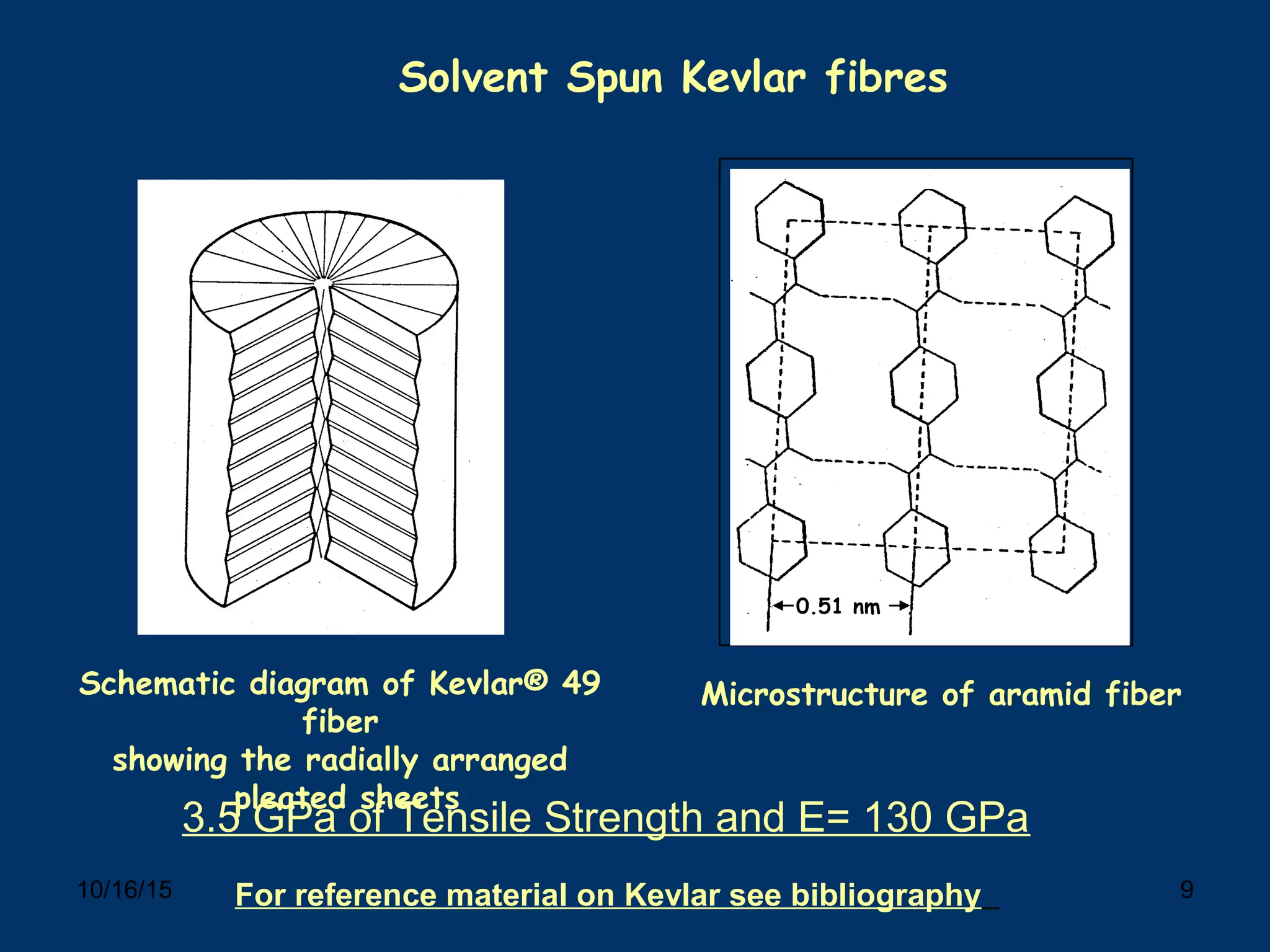
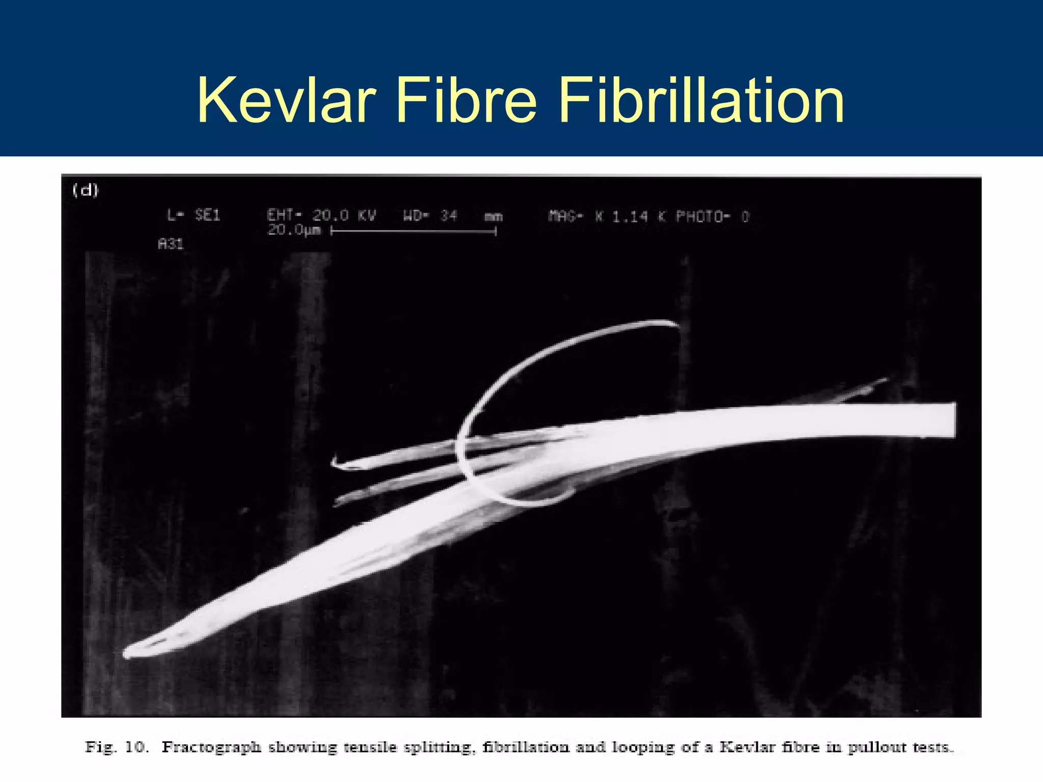


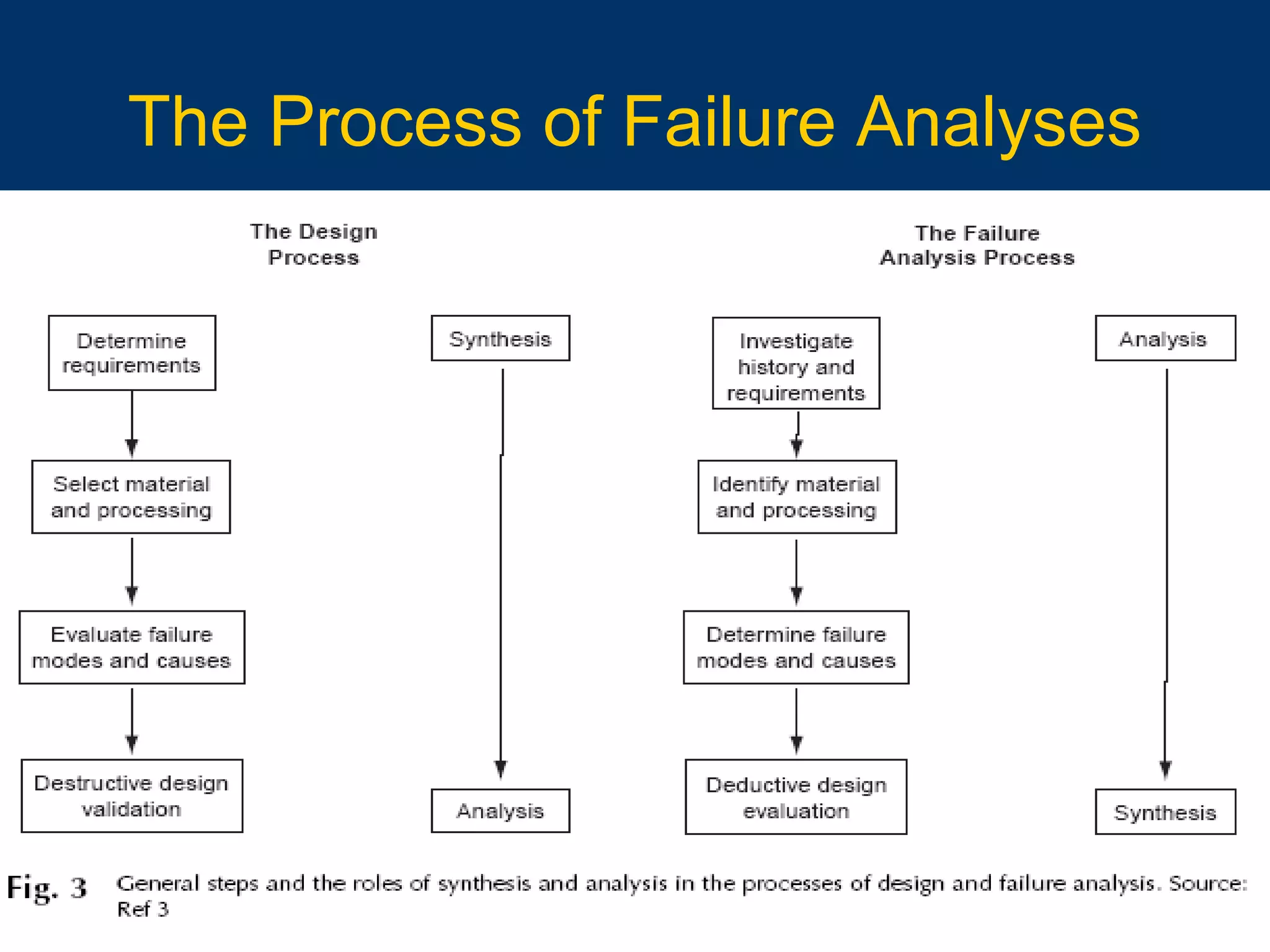
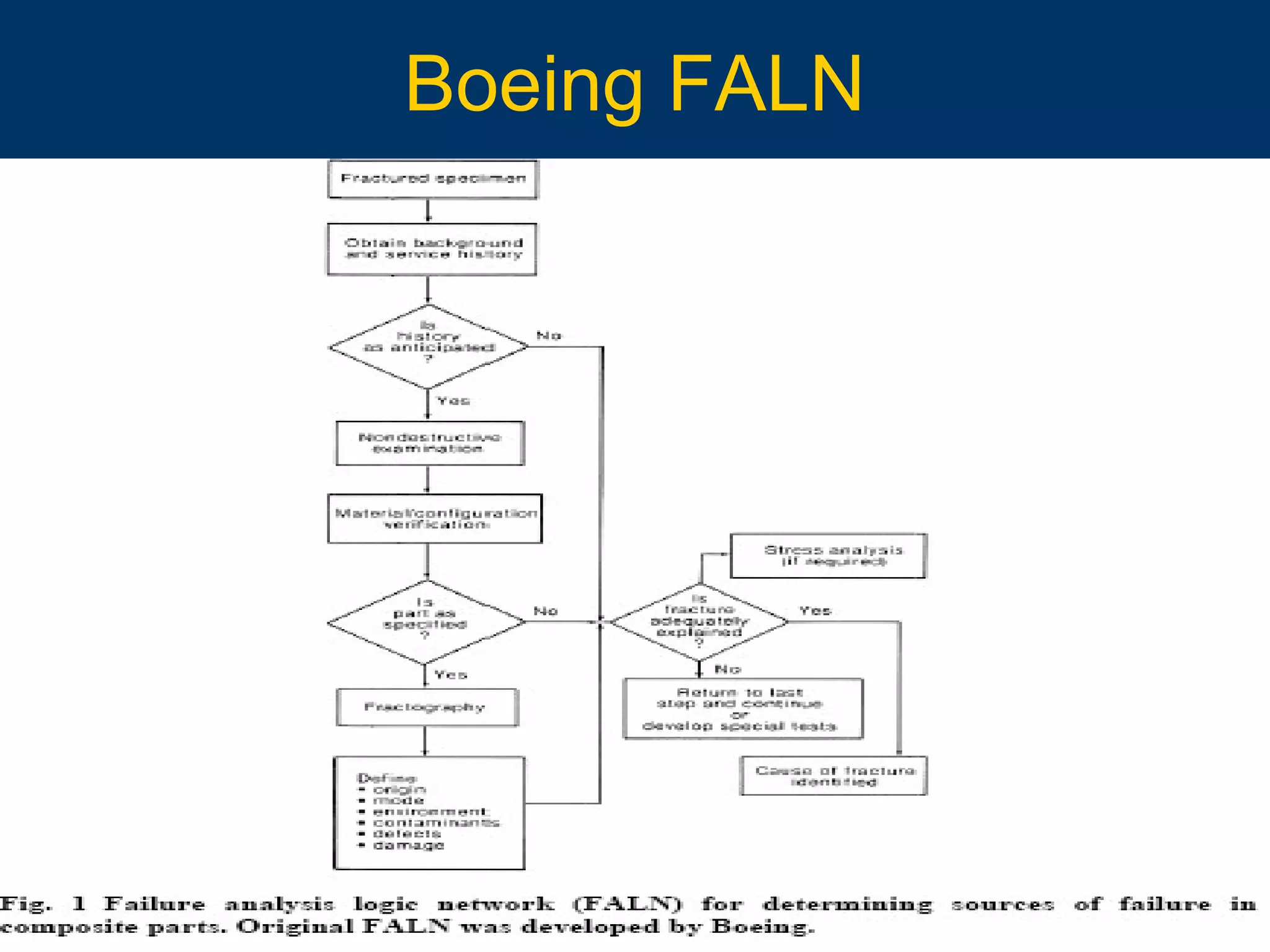
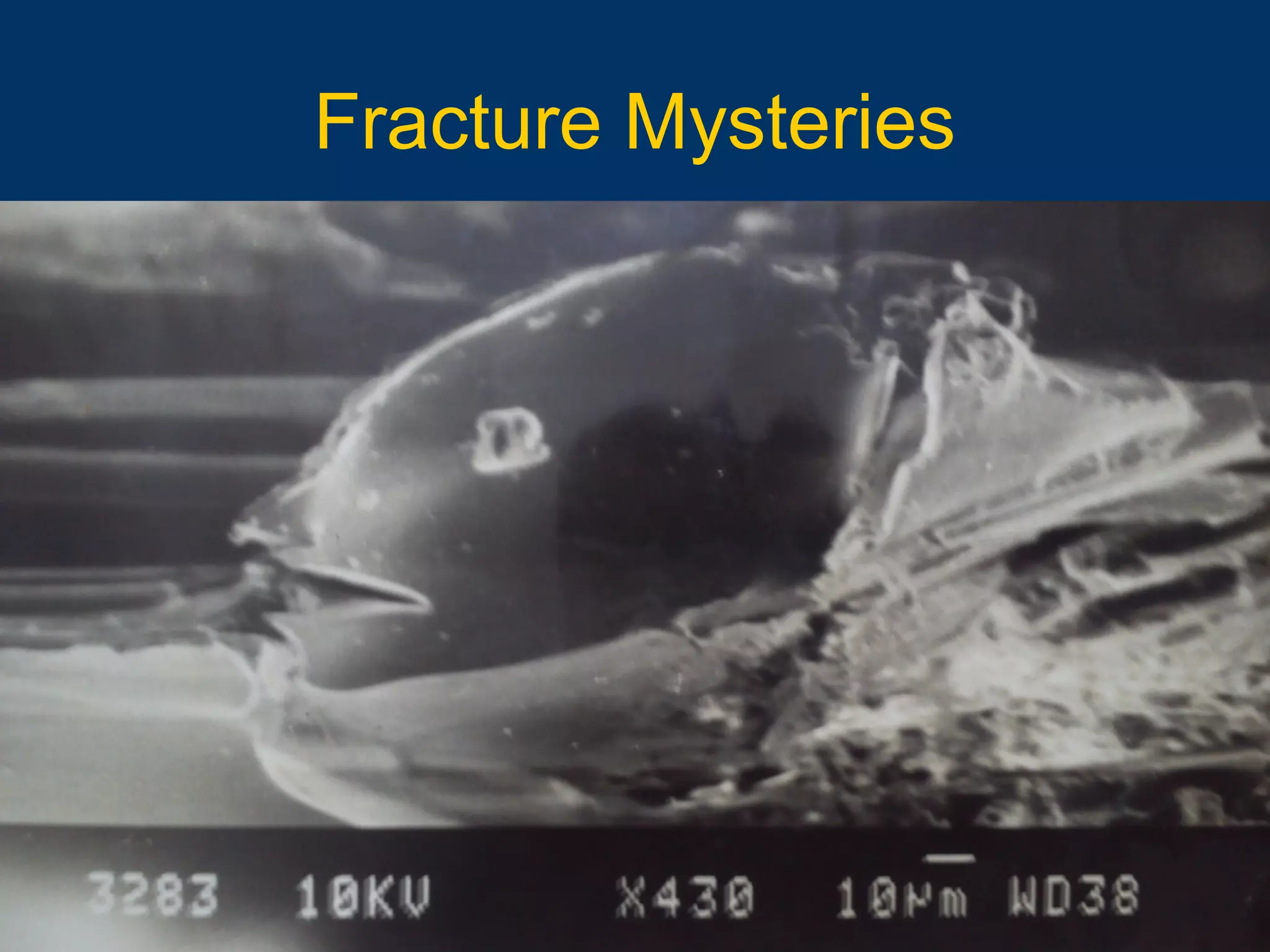

The document discusses fracture and failure analyses of plastics and reinforced plastics, highlighting definitions, structures, and properties of materials, as well as testing methods and failure theories. It covers various types of materials, including Kevlar and natural fibers, along with their mechanical behavior under different conditions. The document aims to provide insights into improving design and manufacturing processes based on failure feedback and analysis.