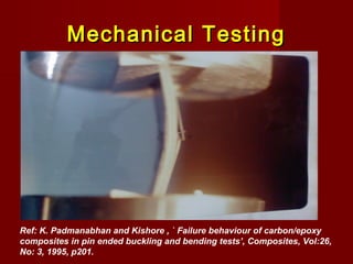
Downloaded 116 times


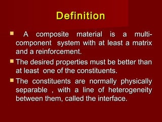

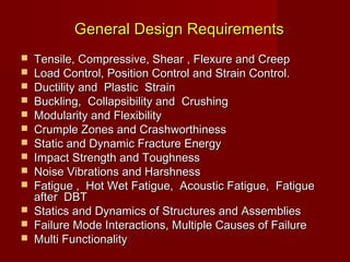
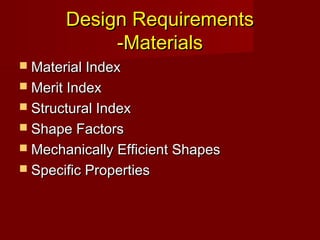
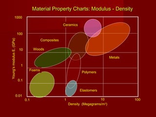
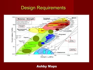
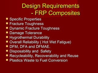


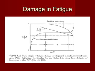
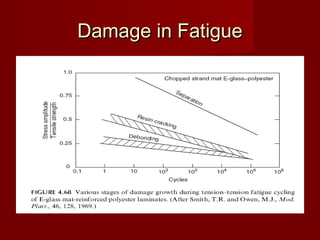
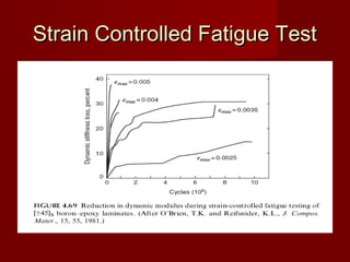
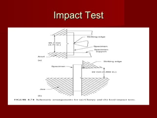
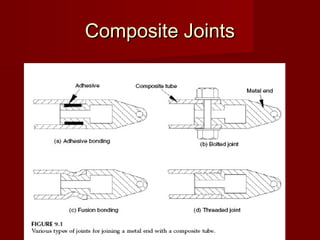
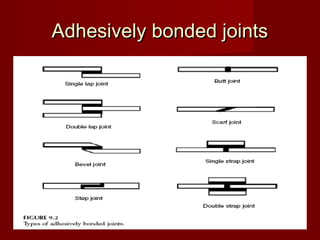
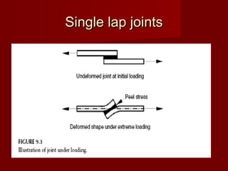
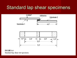


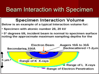
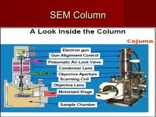


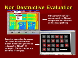
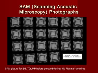
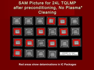
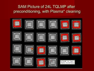


This document discusses measurement techniques for advanced materials systems. It covers topics like design considerations for advanced materials, fracture and failure analysis of composites, non-destructive testing and finite element analysis, innovations in advanced materials testing, and case studies. Measurement of properties like tensile, compressive, flexural, shear, fatigue, impact and hygrothermal behavior are described along with various testing standards and methods. Micromechanics modeling and nanoscale characterization techniques are also mentioned.