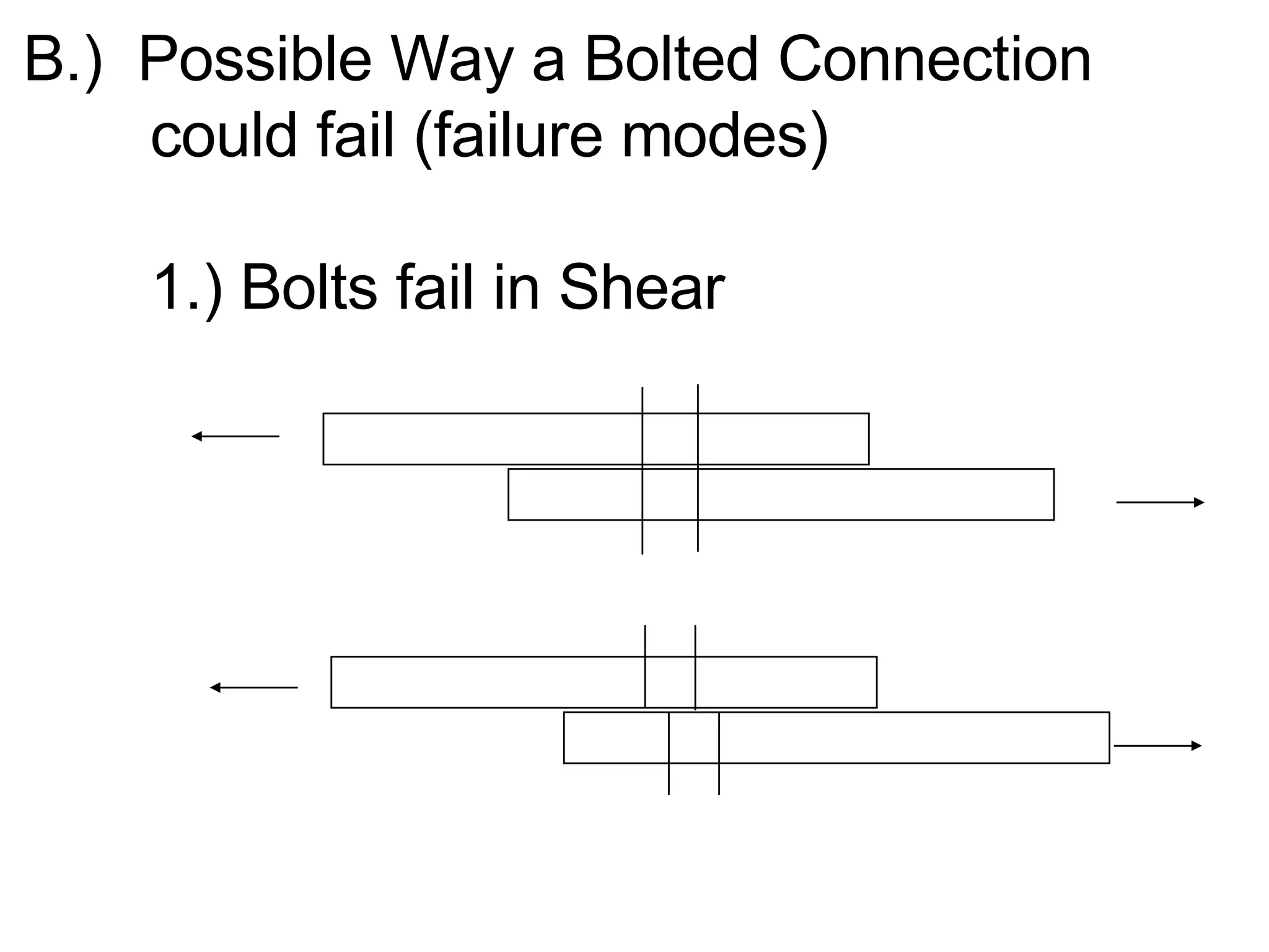
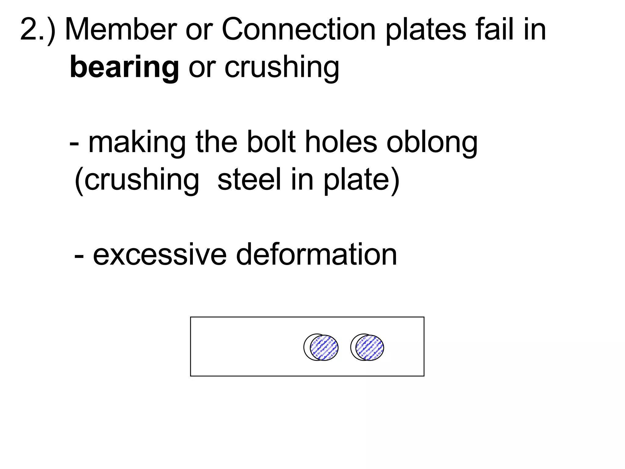
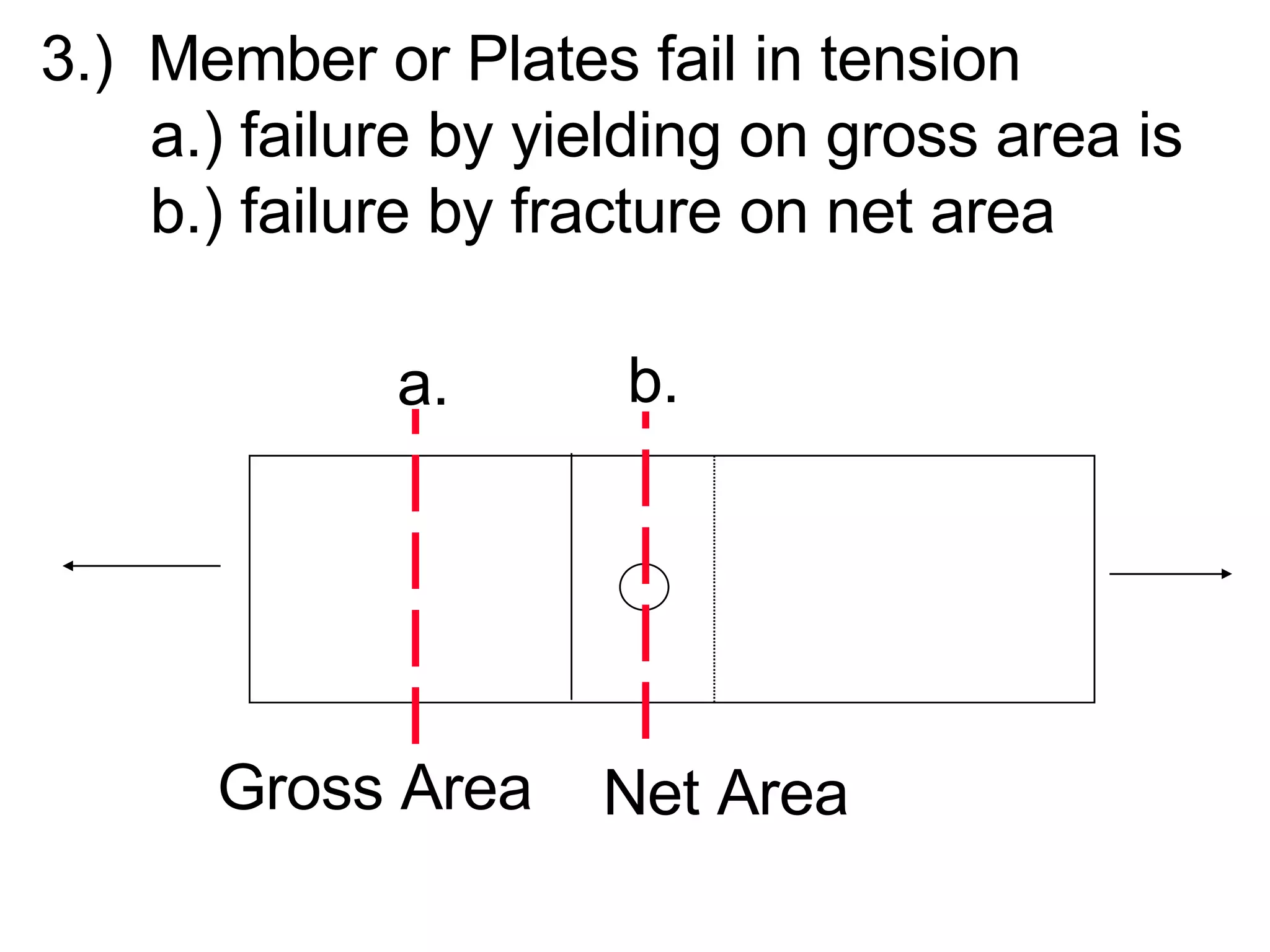
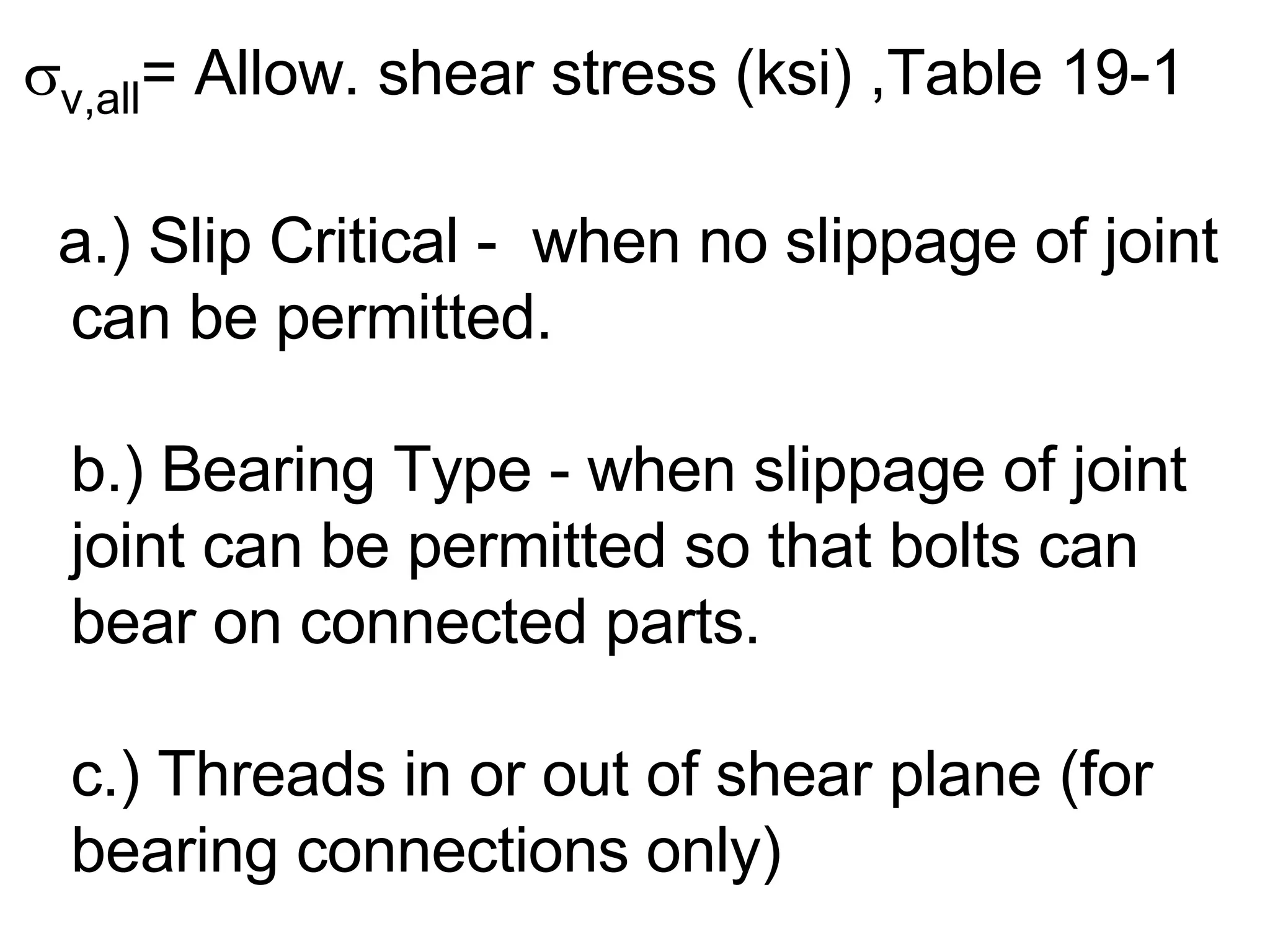
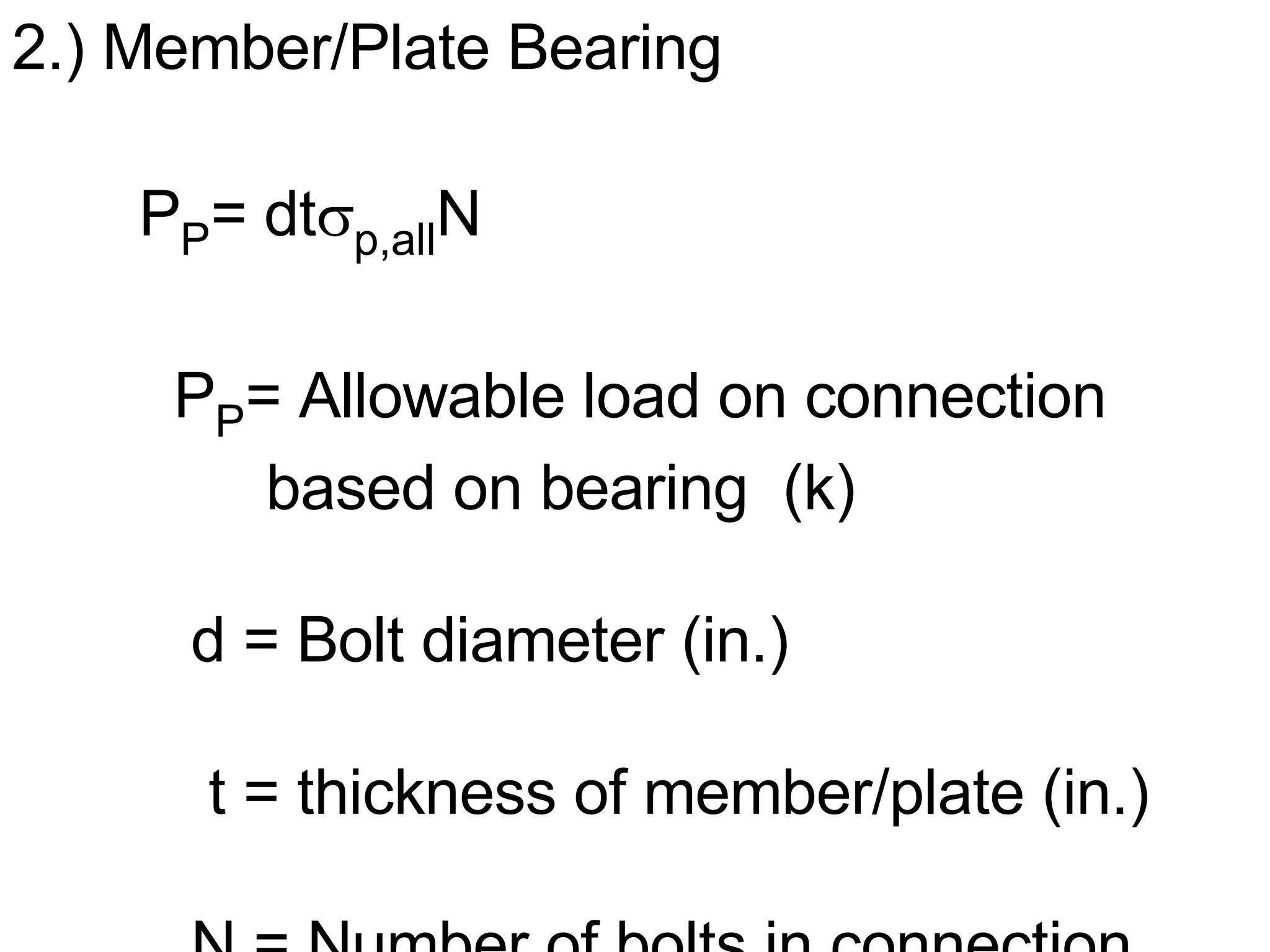
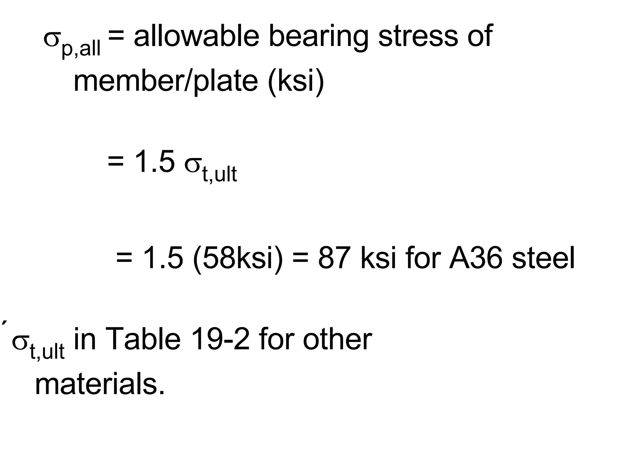
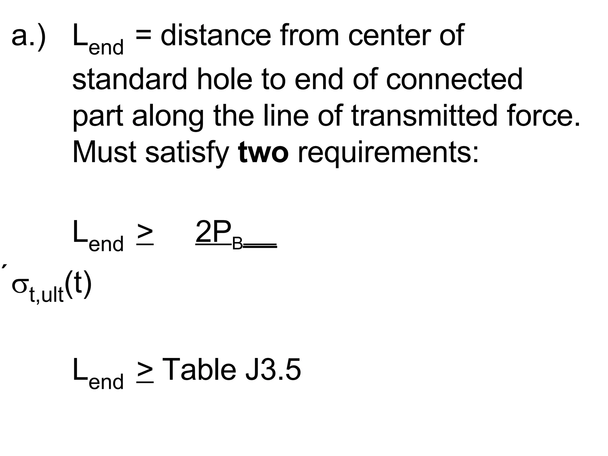
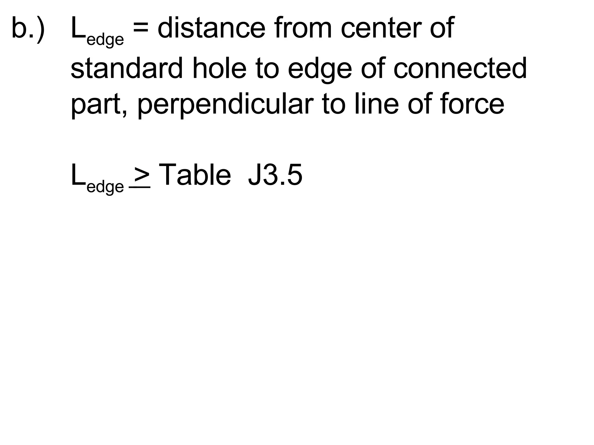
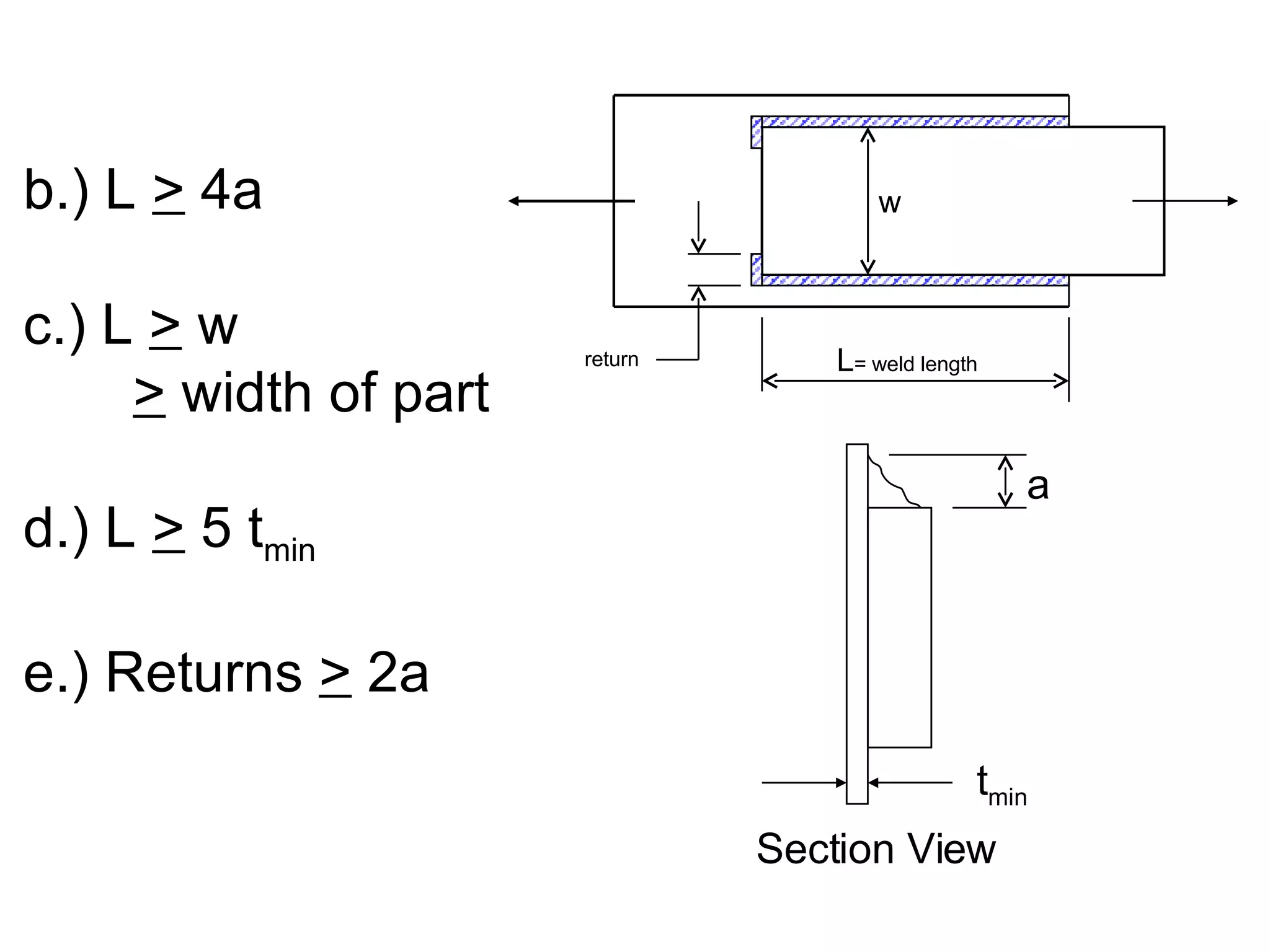
X.)  Bolted Connections (Steel)  A.) Introduction 1.) Types of bolts used with  structural steel   a.)  A307  - low carbon (lowest    strength) standard head size. b.) A325  - high strength - heavy    duty nut.
c.)  A490   - high strength - heavy    duty nut.  Sizes range from 1/2” to    1-1/2” in 1/8” increments.
2.)  Types of Connections a.) Tension/Compression Connection (Axial Members - Trusses) i.) Lap Joint - Bolts in single shear - Eccentric - not as good
ii.) Butt Joint - bolts in  Double Shear   - concentric  - better
b.) Shear Connection (Beams) -Simple Support (No moment  transferred at connection)   - Connect web only - Bolts in Shear + +
c.)  Moment & Shear (Beam Connections) - Fixed Support - Connect Flange & Web + + d.)  Any combination of  a.), b.), & c.) + +
B.)  Possible Way a Bolted Connection  could fail (failure modes) 1.) Bolts fail in Shear
2.) Member or Connection plates fail in    bearing  or crushing   - making the bolt holes oblong  (crushing  steel in plate) - excessive deformation
3.)  Member or Plates fail in tension a.) failure by yielding on gross area is   b.) failure by fracture on net area Gross Area Net Area a. b.
4.)  Member or Connecting plates fail by  end or edge tear-out end  distance too small or edge  distance too small
C.) Design of Bolted Connections - check all 4 possible failure modes:   1.) Bolt Shear 2.) Member/Plate bearing failure 3.) Member/Plate tension failure 4.) Member/Plate end or edge tear-out
  1.) Bolt Shear   P V = A B  v,all Nn   N=  __ P v ___  (solving for N)   nA B  v,all P v = allowable load on connection,  based on bolt shear (k) A B = C.S.A. of one bolt (in 2 ) N =  No. of bolts in connection n= number of shear planes
 v,all = Allow. shear stress (ksi) ,Table 19-1 a.) Slip Critical -  when no slippage of joint can be permitted. b.) Bearing Type - when slippage of joint joint can be permitted so that bolts can bear on connected parts. c.) Threads in or out of shear plane (for bearing connections only)
threads  in  shear  plane threads  not  in shear  plane
2.) Member/Plate Bearing P P = dt  p,all N   P P = Allowable load on connection  based on bearing  (k)   d = Bolt diameter (in.)   t = thickness of member/plate (in.)   N = Number of bolts in connection
   p,all  = allowable bearing stress of  member/plate (ksi)   = 1.5   t,ult   = 1.5 (58ksi) = 87 ksi for A36 steel  t,ult  in Table 19-2 for other  materials.
3.) Tension in member/plates -must satisfy  two requirements: P all  <   A g  (0.60  Y ) P all  < A n  (0.50   t,ult )   A g  = Gross CSA of member or  connection plate  Y = yield strength of member or  plate
  A n  = Net CSA of member or plate    = A g  - A holes    t,ult  = ultimate strength of member or    plate
4.)  Bolt Spacing Edge/End Distance P L B L end L edge L edge L B
a.)  L end   = distance from center of  standard hole to end of connected  part along the line of transmitted force. Must satisfy  two  requirements: L end  >   2P B __    t,ult (t)  L end  >  Table J3.5
  P B = Applied load per bolt = P/N  t,ult = ultimate strength of member/plate   t = thickness of member or plate
b.)  L edge  = distance from center of  standard hole to edge of connected  part, perpendicular to line of force L edge  >  Table  J3.5
c.)  L B  = Distance between centerlines of  standard holes. Again,  two  criteria L B  >   2.67 d  (all directions)   L B  >   2P B __ +  d  (in direction of load)    t,ult (t)  2 d = bolt diameter P B   t,ult  , & t  defined previously


A.) INTRO. TO WELDED CONNECTIONS 1.) 6500 o F electric arc melts the weld electrode to the material being connected ( the base metal). 2.) Weld electrode must be compatible material for the base metal, i.e. same chemical makeup
3.) E60xx means 60 ksi ultimate strength would use with low carbon (A36 or 1020) steel. 4.) Weld geometry a.) Groove welds: - Full Penetration - Partial Penetration b.) Fillet Welds
B.) WELDED CONNECTION STRENGTH 1.) Groove Welds: Full strength of the connected part is developed if: a.) full penetration b.) full length Edge prep. increases cost
2.) Fillet Welds Required size (“a” dimension) of weld is controlled by: a.) Minimum size is controlled by thickness of the thicker of two parts joined. (Table 19-4) b.) Maximum size is controlled by the  thickness of the welded edge. (Table 19-4)
2.) Fillet Welds b.) Maximum size: a max t
2.) Fillet Welds Required length of weld (L) is controlled by: a.) weld shear strength: P v  =   v,all  t e   (units of lb/in)   = (0.3  t,u  )   t e   t e  = “effective throat thickness”   = a(sin45 o ) = 0.707a   P v  =(0.3  t,u  )   (0.707a ) P v  = 0.212   t,u  a   (units of lb/in of weld)
b.) L  >  4a c.) L  >  w >  width of part d.) L  >  5 t min e.) Returns  >  2a return L = weld length Section View w t min a
 

311 C H19

  • 1.
    X.) BoltedConnections (Steel) A.) Introduction 1.) Types of bolts used with structural steel a.) A307 - low carbon (lowest strength) standard head size. b.) A325 - high strength - heavy duty nut.
  • 2.
    c.) A490 - high strength - heavy duty nut. Sizes range from 1/2” to 1-1/2” in 1/8” increments.
  • 3.
    2.) Typesof Connections a.) Tension/Compression Connection (Axial Members - Trusses) i.) Lap Joint - Bolts in single shear - Eccentric - not as good
  • 4.
    ii.) Butt Joint- bolts in Double Shear - concentric - better
  • 5.
    b.) Shear Connection(Beams) -Simple Support (No moment transferred at connection) - Connect web only - Bolts in Shear + +
  • 6.
    c.) Moment& Shear (Beam Connections) - Fixed Support - Connect Flange & Web + + d.) Any combination of a.), b.), & c.) + +
  • 7.
    B.) PossibleWay a Bolted Connection could fail (failure modes) 1.) Bolts fail in Shear
  • 8.
    2.) Member orConnection plates fail in bearing or crushing - making the bolt holes oblong (crushing steel in plate) - excessive deformation
  • 9.
    3.) Memberor Plates fail in tension a.) failure by yielding on gross area is b.) failure by fracture on net area Gross Area Net Area a. b.
  • 10.
    4.) Memberor Connecting plates fail by end or edge tear-out end distance too small or edge distance too small
  • 11.
    C.) Design ofBolted Connections - check all 4 possible failure modes: 1.) Bolt Shear 2.) Member/Plate bearing failure 3.) Member/Plate tension failure 4.) Member/Plate end or edge tear-out
  • 12.
    1.)Bolt Shear P V = A B  v,all Nn N= __ P v ___ (solving for N) nA B  v,all P v = allowable load on connection, based on bolt shear (k) A B = C.S.A. of one bolt (in 2 ) N = No. of bolts in connection n= number of shear planes
  • 13.
     v,all =Allow. shear stress (ksi) ,Table 19-1 a.) Slip Critical - when no slippage of joint can be permitted. b.) Bearing Type - when slippage of joint joint can be permitted so that bolts can bear on connected parts. c.) Threads in or out of shear plane (for bearing connections only)
  • 14.
    threads in shear plane threads not in shear plane
  • 15.
    2.) Member/Plate BearingP P = dt  p,all N P P = Allowable load on connection based on bearing (k) d = Bolt diameter (in.) t = thickness of member/plate (in.) N = Number of bolts in connection
  • 16.
    p,all = allowable bearing stress of member/plate (ksi) = 1.5  t,ult = 1.5 (58ksi) = 87 ksi for A36 steel  t,ult in Table 19-2 for other materials.
  • 17.
    3.) Tension inmember/plates -must satisfy two requirements: P all < A g (0.60  Y ) P all < A n (0.50  t,ult ) A g = Gross CSA of member or connection plate  Y = yield strength of member or plate
  • 18.
    An = Net CSA of member or plate = A g - A holes  t,ult = ultimate strength of member or plate
  • 19.
    4.) BoltSpacing Edge/End Distance P L B L end L edge L edge L B
  • 20.
    a.) Lend = distance from center of standard hole to end of connected part along the line of transmitted force. Must satisfy two requirements: L end > 2P B __  t,ult (t) L end > Table J3.5
  • 21.
    PB = Applied load per bolt = P/N  t,ult = ultimate strength of member/plate t = thickness of member or plate
  • 22.
    b.) Ledge = distance from center of standard hole to edge of connected part, perpendicular to line of force L edge > Table J3.5
  • 23.
    c.) LB = Distance between centerlines of standard holes. Again, two criteria L B > 2.67 d (all directions) L B > 2P B __ + d (in direction of load)  t,ult (t) 2 d = bolt diameter P B  t,ult , & t defined previously
  • 24.
  • 25.
  • 26.
  • 27.
  • 28.
  • 29.
  • 30.
  • 31.
  • 32.
  • 33.
  • 34.
    A.) INTRO. TOWELDED CONNECTIONS 1.) 6500 o F electric arc melts the weld electrode to the material being connected ( the base metal). 2.) Weld electrode must be compatible material for the base metal, i.e. same chemical makeup
  • 35.
    3.) E60xx means60 ksi ultimate strength would use with low carbon (A36 or 1020) steel. 4.) Weld geometry a.) Groove welds: - Full Penetration - Partial Penetration b.) Fillet Welds
  • 36.
    B.) WELDED CONNECTIONSTRENGTH 1.) Groove Welds: Full strength of the connected part is developed if: a.) full penetration b.) full length Edge prep. increases cost
  • 37.
    2.) Fillet WeldsRequired size (“a” dimension) of weld is controlled by: a.) Minimum size is controlled by thickness of the thicker of two parts joined. (Table 19-4) b.) Maximum size is controlled by the thickness of the welded edge. (Table 19-4)
  • 38.
    2.) Fillet Weldsb.) Maximum size: a max t
  • 39.
    2.) Fillet WeldsRequired length of weld (L) is controlled by: a.) weld shear strength: P v =  v,all t e (units of lb/in) = (0.3  t,u ) t e t e = “effective throat thickness” = a(sin45 o ) = 0.707a P v =(0.3  t,u ) (0.707a ) P v = 0.212  t,u a (units of lb/in of weld)
  • 40.
    b.) L > 4a c.) L > w > width of part d.) L > 5 t min e.) Returns > 2a return L = weld length Section View w t min a
  • 41.