Download to read offline


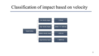
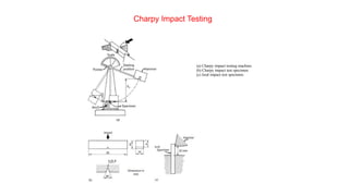

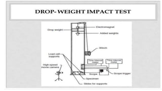
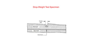


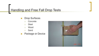
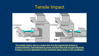


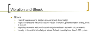


The document discusses various impact and shock testing methods for plastics and metals, including Izod, Charpy, drop weight, and ballistic impact tests. It highlights the importance of testing standards for automotive crashworthiness and the testing procedures for different materials, as well as factors influencing impact force and vehicle design to minimize occupant injury during collisions. Additionally, it covers shock and vibration testing methodologies, detailing the effects of temperature variations and sudden stress on materials.