Downloaded 565 times

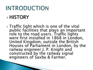
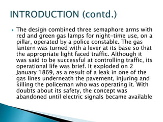


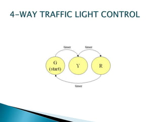
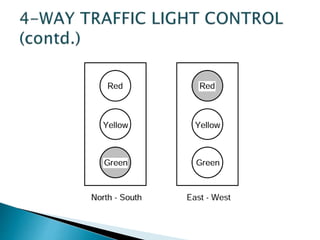

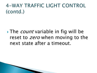


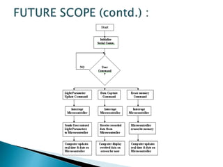


This presentation summarizes the history and development of traffic lights. It discusses how the first traffic light was installed in London in 1868 [1]. It then provides details on the typical light sequences of red, yellow, and green [2]. The presentation goes on to describe how a basic four-way traffic light system can be modeled using a state diagram and Verilog code [3]. It concludes by discussing how more advanced traffic light controllers can help improve urban traffic flow.


![project_ppt[1].pptx](https://cdn.slidesharecdn.com/ss_thumbnails/projectppt1-230708160322-468b41fc-thumbnail.jpg?width=640&height=640&fit=bounds)