Downloaded 180 times

![<<<***>>>
[***Thank u***]
<<<***>>>](https://image.slidesharecdn.com/ppt1-121103220336-phpapp01/85/Ppt-1-37-320.jpg)

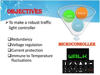
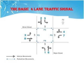
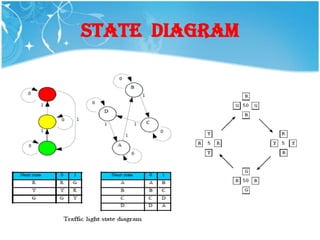
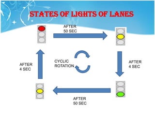
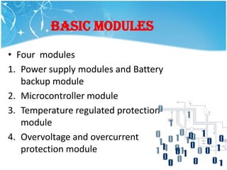
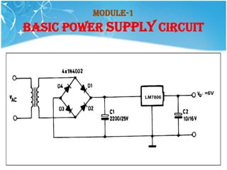
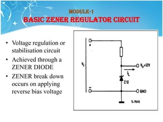
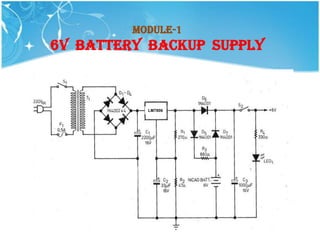
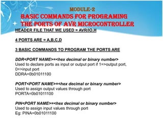
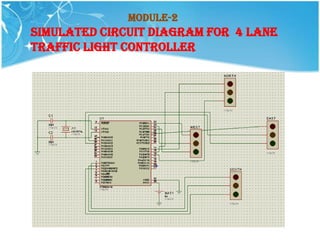
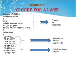
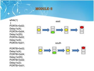
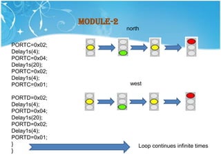
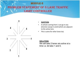
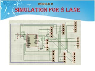
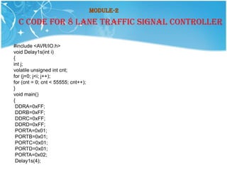
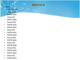
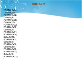
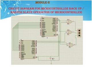
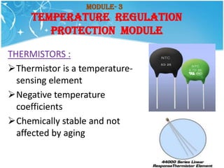
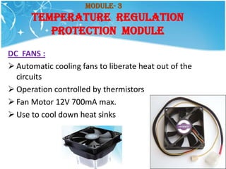
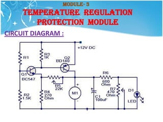
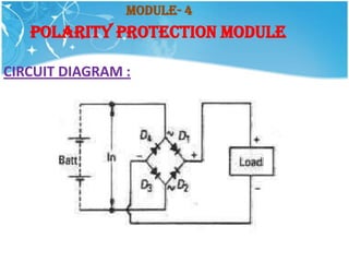
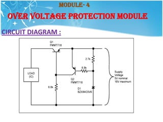
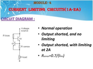
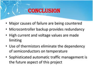
This document describes the design of a robust traffic light controller. It discusses the historical use of traffic lights and outlines objectives to make the controller redundant, regulate voltage, protect from overcurrent and temperature fluctuations. It then describes the basic modules used - a power supply with battery backup, a microcontroller module, a temperature regulation module, and overvoltage/current protection. Code examples are provided for programming the microcontroller ports to control 4-lane and 8-lane traffic light sequences. Diagrams show the circuit designs for the modules. The conclusion states that this controller aims to address major failure causes through redundancy, limiting high voltages/currents, and protecting from temperature changes.


![5G Explained! A High Level Overview [Introduction]](https://cdn.slidesharecdn.com/ss_thumbnails/5gexplainedahighleveloverview-260119165306-cc137a3e-thumbnail.jpg?width=640&height=640&fit=bounds)


