
Recommended
More Related Content
What's hot
What's hot (20)
Similar to Lateral earth pressure theories by abhishek sharma
Similar to Lateral earth pressure theories by abhishek sharma (20)
Recently uploaded
Recently uploaded (20)
Lateral earth pressure theories by abhishek sharma
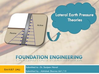
- 1. Submitted to : Dr. Sanjeev Naval Submitted by : Abhishek Sharma 661/15 D.A.V.I.E.T (JAL)
- 2. 1.INTRODUCTION In this presentation, we will analyze some typical earth- retaining structures to determine their stability. The emphases will be on gaining an understanding of the forces that provoke failures and methods of analysis of simple earth-retaining structures. 2 When you complete this chapter, you should be able to: • Understand and determine lateral earth pressures. • Understand the forces that lead to instability of earth-retaining structures. • Determine the stability of simple earth-retaining structures 2 ABHISHEK SHARMA 661
- 3. 2.Importance of calculation of lateral earth pressure ? Soil is neither a solid nor a liquid, but it exhibits some of the characteristics of both. One of the characteristics similar to that of a liquid is its tendency to exert a lateral pressure against any object in contact. In case of water, pressure is equal in all direction but in case of soil, horizontal pressure may be less or more than vertical pressure. 3 3 ABHISHEK SHARMA 661
- 4. 3.EARTH RETAINING STRUCTURES Structures which are used to hold back a soil mass or water are called retaining structures. Retaining walls, sheet pile walls, crib walls, sheeting in excavations, basement walls etc are examples of earth retaining structures. 4 4 ABHISHEK SHARMA 661
- 5. Type of Earth Retaining Structures Earth-retaining structures may be broadly classified as • Retaining walls and • Sheet Pile walls (i) Gravity retaining walls - usually of masonry or mass concrete (ii) Cantilever walls (iii) Counterfort walls usually of reinforced concrete. (iv) Buttress walls Retaining Walls are further classified as : 5 ABHISHEK SHARMA 661
- 6. Gravity Retaining Wall Gravity walls depend on their weight for stability; walls up to 2 m height are invariably of this type. Nowadays Geosynthetics materials are also use as reinforcement. 6
- 7. Cantiliver Retaining Wall R.C. Cantilever walls have a vertical or inclined stem monolithic with a base slab. These are considered suitable up to a height of 7.5 m. A vertical or inclined stem is used in counter-fort walls, supported by the base slab as well as by counter-forts with which it is monolithic. 7
- 8. Counterfort & Buttress Retaining Wall 8 ABHISHEK SHARMA 661
- 9. BUTTRESS RETAINING WALL COUNTERFORT RETAINING WALL 9 ABHISHEK SHARMA 661
- 10. Sheet pile walls may be further classified as: • Cantilever sheet pile walls and • Anchored sheet pile walls, also called ‗bulkheads‘. Cantilever sheet pile walls are held in the ground by the passive resistance of the soil both in front of and behind them. Anchored sheet pile wall or bulkhead is fixed at its base as a cantilever wall but supported by tie-rods near the top, sometimes using two rows of ties and properly anchored to a deadman. THESE ARE ALSO CALLED FLEXIBLE RETAINING WALLS 10 ABHISHEK SHARMA 661
- 12. SHEET PILE RETAINING WALL SHEET PILE RETAINING WALL WITH ANCHORAGE 12 ABHISHEK SHARMA 661
- 14. 4.STATE OF EQUILIBRIUM The state of Equilibrium of soil can be divided into two states : a) State of Elastic Equilibrium When a small change in stress produces a corresponding small change in strain or we can say that in this state every point in given soil mass is not at the verge of failure. b) State of Plastic Equilibrium When irreversible strain takes place at a constant stress or we can say that in this state every point in given soil mass is at the verge of failure. 14 ABHISHEK SHARMA 661
- 15. 5.LATERAL EARTH PRESSURE Lateral earth pressure is the force exerted by the soil mass upon an earth-retaining structure, such as a retaining wall. There are two distinct kinds of lateral earth pressure; the nature of each is to be clearly understood. EARTH PRESSURE AT REST ACTIVE EARTH PRESSURE PASSIVE EARTH PRESSURE 15 ABHISHEK SHARMA 661
- 16. • First, let us consider a retaining wall which holds back a mass of soil. • When there is no movement of retaining wall and soil mass then the pressure exerts by soil on retaining wall is called earth pressure at rest. Earth pressure at rest16 ABHISHEK SHARMA 661
- 17. The soil exerts a push against the wall by virtue of its tendency to slip laterally and seek its natural slope or angle of repose, thus making the wall to move slightly away from the backfilled soil mass. This kind of pressure is known as the ‗active‘ earth pressure of the soil. The soil, being the actuating element, is considered to be active and hence the name active earth pressure. ACTIVE EARTH PRESSURE17 ABHISHEK SHARMA 661
- 18. Let us imagine that in some manner the retaining wall is caused to move toward the soil. In such a case the retaining wall or the earth-retaining structure is the actuating element and the soil provides the resistance which soil develops in response to movement of the structure toward it is called the ‗passive earth pressure‘, or more appropriately ‗passive earth resistance‘ which may be very much greater than the active earth pressure PASSIVE EARTH PRESSURE18 ABHISHEK SHARMA 661
- 19. IMPORTANT NOTE : In the case of Active pressure, • the structure tends to move away from the soil • causing strains in the soil mass, which in turn, • mobilise shearing stresses; • these stresses help to support the soil mass and thus • tend to reduce the pressure exerted by the soil against the structure In the case of Passive pressure, • the structure tends to move towards the soil • causing strains in the soil mass, which in turn, • mobilise shearing stresses in opposite direction as in active case; • these stresses doesn‘t help to support the soil mass and thus • tend to increase the pressure exerted by the soil against the structure19 ABHISHEK SHARMA 661
- 20. Logically, therefore, there must be a situation intermediate between the two (active and passive) when the retaining structure is perfectly stationary and does not move in either direction. The pressure which develops in this condition is called ‗earth pressure at rest’. Its value is little larger than the limiting value of active pressure, but is considerably less than the maximum passive resistance. 20 ABHISHEK SHARMA 661
- 21. Very little movement about 0.5% horizontal strain required to mobilise the ACTIVE PRESSURE. Larger movements about 2% horizontal strain for dense sands & 15% for loose sands may be require to mobilise full PASSIVE PRESSURE (LAMBE AND WHITEMAN 1969) QUICK NOTE 21 ABHISHEK SHARMA 661
- 22. In a later sub-section , it will be shown that the failure planes will be inclined to horizontal at (45° + φ/2) and (45° – φ/2) in the active and passive cases, respectively. This means that the width of the sliding wedge at the top of the wall will be H cot (45° + φ/2) and H cot (45° – φ/2) for active and passive cases, respectively. H being the height of the wall. For average values of φ, these will be approximately H/2 and 2H. The strains mentioned by Lambe and Whitman (1969) will then amount to a horizontal movement at the top of the wall of 0.0025 H for the active case and 0.4 H to 0.30 H for the passive case. 22 ABHISHEK SHARMA 661
- 23. Terzaghi‘s observation (Terzaghi, 1936) This agrees fairly well with that a movement of 0.005 H of the top of the wall, or even less, is adequate for full mobilisation of ACTIVE STATE. (In fact, Terzaghi’s experiments in the 1920’s indicated that even 0.001 H is adequate for this. 23 ABHISHEK SHARMA 661
- 24. The other factors which affect the lateral earth pressure are • the nature of soil —cohesive or cohesionless, • porosity, • water content and • unit weight of soil. The magnitude of the total earth pressure, or to be more precise, force on the structure, is dependent on the height of the backfilled soil as also on the nature of pressure distribution along the height. 24 ABHISHEK SHARMA 661
- 25. There are two reasons why less strain is required to reach the active condition than to reach the passive condition. First, an unloading (the active state) always involves less strain than a loading (passive state). Second, the stress change in passing to the active state is much less than the stress change in passing to the passive state. (Lambe and Whitman, 1969). Q. Why less strain is required to reach mobilised state in active case than passive case? 25 ABHISHEK SHARMA 661
- 26. 6. DEFINITIONS OF KEY TERMS Backfill is the soil retained by the wall. Active earth pressure coefficient (Ka) is the ratio between the lateral and vertical principal effective stresses at the limiting stress state when an earth-retaining structure moves away (by a small amount) from the backfill (retained soil). Passive earth pressure coefficient (Kp) is the ratio between the lateral and vertical principal effective stresses at the limiting stress state when an earth-retaining structure is forced against a soil mass. 26 ABHISHEK SHARMA 661
- 27. Gravity retaining wall is a massive concrete wall relying on its mass to resist the lateral forces from the retained soil mass. Flexible retaining wall or sheet pile wall is a long, slender wall relying on passive resistance and anchors or props for its stability. Mechanical stabilized earth is a gravity-type retaining wall in which the soil is reinforced by thin reinforcing elements (steel, fabric, fibers, etc.). Continue 27 ABHISHEK SHARMA 661
- 28. 7.LATERAL EARTH PRESSURE AT REST Earth pressure at rest may be obtained theoretically from the theory of elasticity applied to an element of soil, remembering that the lateral strain of the element is zero. Referring to in next slide the principal stresses acting on an element of soil situated at a depth z from the surface in semi-infinite, elastic, homogeneous and isotropic soil mass are σv and σh as shown. σv and σh denoting the stresses in the vertical and horizontal directions respectively. The soil deforms vertically under its self-weight but is prevented from deforming laterally because of an infinite extent in all lateral direction. 28 ABHISHEK SHARMA 661
- 29. Let Es and v be the modulus of elasticity and Poisson‘s ratio of the soil respectively. 29 ABHISHEK SHARMA 661
- 30. Lateral strain = But σv = γ. z, where γ is the appropriate unit weight of the soil depending upon its condition. Let us denote by K0, which is known as the “Coefficient of earth pressure at rest” and which is the ratio of the intensity of the earth pressure at rest to the vertical stress at a specified depth. ∴ ∴ It is equal to zero because earth is at rest and there is no lateral strain. σh = K0. γ.z When soil is not consist of any type of moisture 30 ABHISHEK SHARMA 661
- 31. σh = K0. γ’.z + γw z When soil is in submerged condition where γ’ is submerged unit weight of soil If a structure such as a retaining wall of height H is interposed from the surface and imagined to be held without yield, the total thrust on the wall unit length P0, is given by: This is considered to act at (1/3) H above the base of wall or (2/3)H from top of wall. As has been indicated in the previous chapter, choosing an appropriate value for the Poisson’s ratio, ν, is by no means easy; this is the limitation in arriving at K0 31 ABHISHEK SHARMA 661
- 32. Various researchers proposed empirical relationships for K0. some of are given below: FOR OVERCONSOLIDATED SOILS, KO = KO (N.C SOIL) X SQ. ROOT OF O.C.R WHERE KO(N.C SOIL) IS DETERMINE BY KENNEY EQUATION, AND O.C.R IS OVERCONSOLIDTATED RATIO. 32 ABHISHEK SHARMA 661
- 33. φ′ in these equations represents the effective angle of friction of the soil Ip is the plasticity index. Brooker and Ireland (1965) recommend Jaky‘s equation for cohesioness soils and their own equation, given above, for cohesive soils. However, Alpan (1967) recommends Jaky‘s equation for cohesionless soils and Kenney equation for cohesive soils as does Kenney (1959). 33 ABHISHEK SHARMA 661
- 34. Certain values of the coefficient of earth pressure at rest are suggested for different soils, based on field data, experimental evidence and experience are given below. 34 ABHISHEK SHARMA 661
- 35. 8. EARTH PRESSURE THEORIES A French military engineer, Vauban, set forth certain rules for the design of revetments in 1687. The magnitude of the lateral earth pressure is evaluated by the application of one or the other of the so-called ‗lateral earth pressure theories‘ or simply ‗earth pressure theories‘. Since then, several investigators have proposed many theories of earth pressure after a lot of experimental and theoretical work. Of all these theories, those given by Coulomb and Rankine stood the test of time and are usually referred to as the ―Classical earth pressure theories‖ 35 ABHISHEK SHARMA 661
- 36. • These theories have been developed originally to apply to cohesionless soil backfill. • Later researchers gave necessary modifications to take into account cohesion, surcharge, submergence, and so on. • Some have evolved graphical procedures to evaluate the total thrust on the retaining structure. ABOUT CLASSICAL EARTH PRESSURE THEORIES Although Coulomb presented his theory nearly a century earlier to Rankine‘s theory, Rankine‘s theory will be presented first due to its relative simplicity. 36 ABHISHEK SHARMA 661
- 37. 8.1 RANKINE EARTH PRESSURE THEORY Rankine (1857) developed his theory of lateral earth pressure when the backfill consists of dry, cohesionless soil. The theory was later extended by Resal (1910) and Bell (1915) to be applicable to cohesive soils. 37 ABHISHEK SHARMA 661 WILLIAM RANKINE (1820–1872)
- 38. ASSUMPTIONS: (i) The soil mass is isotropic, semi infinite, homogeneous, dry and cohesionless. (ii) The ground surface is a plane which may be horizontal or inclined. (iii) The face of the wall in contact with the backfill is vertical and smooth. (This amounts to ignoring the presence of the wall). (iv) The wall yields about the base sufficiently for the active pressure conditions to develop; if it is the passive case that is under consideration, the wall is taken to be pushed sufficiently towards the fill for the passive resistance to be fully mobilised. (v) The rupture surface is planar surface which is obtained by considering the plastic equilibrium of soil. Thus it is seen that, by neglecting wall friction as also cohesion of the backfill, the geotechnical engineer errs on the safe side in the computation of both the active pressure and passive resistance. 38 ABHISHEK SHARMA 661
- 39. 8.1.1 ACTIVE & PASSIVE RANKINE Consider the wall shown in Figure below. If the wall remains rigid and no movement (not even an infinitesimal movement) occurs, then the vertical and horizontal effective stresses at rest on elements A, at the back wall, and B, at the front wall, are: 39 ABHISHEK SHARMA 661
- 40. Let us now assume a rotation about the bottom of the wall sufficient to produce slip planes in the soil mass behind and in front of the wall as shown below. The soil mass at the back of the wall is causing failure, while the soil mass at the front of the wall is resisting failure. In the latter, you have to rotate the wall against the soil to produce failure. 40 ABHISHEK SHARMA 661
- 41. 41 What happens to the lateral effective stresses on elements A and B (Figure on slide 39) when the wall is rotated? The vertical stress will not change on either element, but the lateral effective stress on element ‗A‘ will be reduced for element ‗B‘ will be increased. We can now plot two additional Mohr‘s circles, one to represent the stress state of element A (circle A, Figure on slide 42) other to represent the stress state of element B (circle B, Figure on slide 42). Both circles are drawn such that the decrease (element A) or increase (element B) in lateral effective stress is sufficient to bring the soil to the Mohr–Coulomb limiting stress state. ABHISHEK SHARMA 661
- 42. I = MOHR CIRCLE FOR PRESSURE AT REST A = MOHR CIRCLE FOR ACTIVE PRESSURE B = MOHR CIRCLE FOR PASSIVE PRESSURE σ̍1 = MAJOR PRINCIPAL STRESS σ̍3 = MINOR PRINCIPAL STRESS Ko = EARTH PRESSURE COEFFICIENT AT REST Ka = EARTH PRESSURE COEFFICIENT IN ACTIVE CASE Kp = EARTH PRESSURE COEFFICIENT IN PASSIVE CASE42 ABHISHEK SHARMA 661
- 44. 44 Values given in slide 22 & 23 should also be considered Rotation required to mobilize active and passive resistance. ABHISHEK SHARMA 661
- 45. 45 For element A to reach the failure state, the lateral effective stress must be less than the vertical effective stress, If the shear stress (Ʈ) induced in a soil is less than the peak or critical shear strength, then the soil has reserved shear strength, and we can characterize this reserved shear strength by a factor of safety (FS). For peak condition in dilating soils: The ratio of lateral principal effective stress to vertical principal effective stress at the limiting stress state is given by Equation above for circle A (fig. On slide 42), is where Ka is called the active lateral earth pressure coefficient. ABHISHEK SHARMA 661
- 46. 46 Similarly, for circle B (fig. on slide 42) where Kp is the passive earth pressure coefficient. Relation becomes : Essential points are: 1. The lateral earth pressures on retaining walls are related directly to the vertical effective stress through two coefficients. One is the active earth pressure coefficient, ABHISHEK SHARMA 661
- 47. 47 Continue and the other is the passive earth pressure coefficient, 2. Substantially more movement is required to mobilize the full passive earth pressure than the full active earth pressure. 3. The lateral earth pressure coefficients developed so far are valid only for a smooth, vertical wall supporting a homogeneous soil mass with a horizontal surface. 4. The lateral earth pressure coefficients must be applied only to principal effective stresses. ABHISHEK SHARMA 661
- 48. 48 Some cases : EFFECT OF SUBMERGENCE: When the backfill is fully saturated/submerged, the lateral pressure will be due to two components: (i) Lateral earth pressure due to submerged unit weight of the backfill soil; and (ii) Lateral pressure due to pore water. σh, is given by: σh = Ka.γ ′z + γw.z ABHISHEK SHARMA 661
- 49. 49 IF THE BACKFILL IS SUBMERGED ONLY TO A PART OF ITS HEIGHT The backfill above the water table is considered to be moist. The lateral pressure above the water table is due to the most unit weight of soil, and that below the water table is the sum of that due to the submerged unit weight of the soil and the water pressure Lateral pressure at the base of wall, = Ka.γ.H2 + Ka.γ ′.H1 + γw .H1 ABHISHEK SHARMA 661 Lateral pressure at the base of wall, = Kp.γ.H2 + Kp.γ ′.H1 + γw .H1
- 50. 50 EFFECT OF UNIFORM SURCHARGE The extra loading carried by a retaining structure is known as ‗surcharge‘. In the case of a wall retaining a backfill with horizontal surface level with the top of the wall and carrying a uniform surcharge of intensity q per unit area, the vertical stress at every elevation in the backfill is considered to increase by q. σh = Ka.γ.z + Ka.q ABHISHEK SHARMA 661 σh = Kp.γ.z + Kp.q Active case passive case ABHISHEK SHARMA 661
- 51. 51 EFFECT OF INCLINED SURCHARGE—SLOPING BACKFILL Rankine‘s theory for this case is based on the assumption that a ‗conjugate‘ relationship exists between the vertical pressures and lateral pressures on vertical planes within the soil adjacent to a retaining wall. ABHISHEK SHARMA 661
- 52. 9. Active Earth Pressure of Cohesive Soil52 σ1 = γz, σ3 = σh 1/Nφ = Ka for a cohesionless soil For active case ABHISHEK SHARMA 661
- 53. 53 At the surface, z = 0 and The negative values of active pressure up to a depth equal to half of the so-called ‗critical depth‘ The total active thrust per unit length of the wall is obtained by ABHISHEK SHARMA 661
- 54. 54 For pure clay, φ = 0 The net pressure over depth of 2zc is obviously zero. The critical depth Hc, is given by If φ = 0, ABHISHEK SHARMA 661
- 55. 10. Passive Earth Pressure of Cohesive Soil 55 σ3 = γz and σ1 = σhc For passive case Here, Kp = Nφ in the usual notation. The total passive resistance per unit length of wall is PP = ABHISHEK SHARMA 661
- 57. 11. COULOMB‘S WEDGE THEORY 57 Charles Augustine Coulomb (1776), a famous French scientist and military engineer, was the first to try to give a scientific basis to the hazy and arbitrary ideas existing in his time regarding lateral earth pressure on walls. Assumptions 1. The backfill soil is considered to be dry, homogeneous and isotropic; it is elastically underformable but breakable, granular material, possessing internal friction but no cohesion. ABHISHEK SHARMA 661 Charles-Augustin de Coulomb 14 June 1736 – 23 August 1806
- 58. 58 2. The rupture surface is assumed to be a plane for the sake of convenience in analysis. It passes through the heel of the wall. It is not actually a plane, but is curved and this is known to Coulomb. 3. The sliding wedge acts as a rigid body and the value of the earth thrust is obtained by considering its equilibrium. 4. The position and direction of the earth thrust are assumed to be known. The thrust acts on the back of the wall at a point one-third of the height of the wall above the base of the wall and makes an angle δ, with the normal to the back face of the wall. This is an angle of friction between the wall and backfill soil and is usually called ‘wall friction’. 5. The problem of determining the earth thrust is solved, on the basis of two-dimensional case of ‘plane strain’. This is to say that, the retaining wall is assumed to be of great length and all conditions of the wall and fill remain constant along the length of the wall. Thus, a unit length of the wall perpendicular to the plane of the paper is considered. ABHISHEK SHARMA 661
- 59. 59 6. When the soil wedge is at incipient failure or the sliding of the wedge is impending, the theory gives two limiting values of earth pressure, the least and the greatest (active and passive), compatible with equilibrium. 7. The soil forms a natural slope angle, φ, with the horizontal, without rupture and sliding. This is called the angle of repose and in the case of dry cohesionless soil, it is nothing but the angle of internal friction. The concept of friction was understood by Coulomb. 8. If the wall yields and the rupture of the backfill soil takes place, a soil wedge is torn off from the rest of the soil mass. In the active case, the soil wedge slides sideways and downward over the rupture surface, thus exerting a lateral pressure on the wall. In the case of passive earth resistance, the soil wedge slides sideways and upward on the rupture surface due to the forcing of the wall against the fill. 9. The friction is distributed uniformly on the rupture surface. ABHISHEK SHARMA 661
- 60. 60 10. The back face of the wall is a plane. 11. The following considerations are employed for the determination of the active and passive earth pressures: Active Earth Pressure of Cohesionless Soil ABHISHEK SHARMA 661
- 61. 61 The value of Pa so obtained is written as: For a vertical wall retaining a horizontal backfill for which the angle of wall friction is equal to φ, Ka reduces to α = 90°, δ = 0, and β = 0; ABHISHEK SHARMA 661
- 62. 62 Passive Earth Pressure of Cohesionless Soil ABHISHEK SHARMA 661
- 63. 63 The value of Pp so obtained may be written as For a vertical wall retaining a horizontal backfill and for which the friction is equal to φ, α = 90°, β = 0°, and δ = φ, and Kp reduces to ABHISHEK SHARMA 661
- 64. 12. Comparison of Coulomb‘s Theory with Rankine‘s Theory 64 (i) Coulomb considers a retaining wall and the backfill as a system; he takes into account the friction between the wall and the backfill, while Rankine does not. (ii) The backfill surface may be plane or curved in Coulomb’s theory, but Rankine’s allows only for a plane surface. (iii) In Coulomb’s theory, the total earth thrust is first obtained and its position and direction of the earth pressure are assumed to be known; In Rankine’s theory, plastic equilibrium inside a semiinfinite soil mass is considered, pressures evaluated, a retaining wall is imagined to be interposed later ABHISHEK SHARMA 661
- 65. 65 (iv) Coulomb’s theory is more versatile than Rankine’s in that it can take into account any shape of the backfill surface, break in the wall face or in the surface of the fill, effect of stratification of the backfill, effect of various kinds of surcharge on earth pressure, and the effects of cohesion, adhesion and wall friction. (v) Rankine’s theory is relatively simple and hence is more commonly used, while Coulomb’s theory is more rational and versatile although cumbersome at times; therefore, the use of the latter is called for in important situations or problems. ABHISHEK SHARMA 661
- 66. 66 EXAMPLE 1: A gravity retaining wall retains 12 m of a backfill, γ = 17.7 kN/m3 φ = 25° with a uniform horizontal surface. Assume the wall interface to be vertical, determine the magnitude and point of application of the total active pressure. If the water table is a height of 6 m, how far do the magnitude and the point of application of active pressure changed? ABHISHEK SHARMA 661
- 67. 67 (a) Dry cohesionless fill: H = 12 m φ = 25° γ = 17.7 kN/m3 Active pressure at base of wall = Ka. γH = 86.2 kN/m2 Total active thrust per metre run of wall ABHISHEK SHARMA 661
- 68. 68 This acts at (1/3)H or 4 m above the base of the wall. (b) Water table at 6 m from surface: Active pressure at 6 m depth = 0.406 × 17.7 × 6 = 43.1 kN/m2 Active pressure at the base of the wall = Ka(γ. 6 + γ′. 6) + γw .6 = 0.406 (17.7 × 6 + 10 × 6) + 9.81 × 6 = 67.5 + 58.9 = 126.4 kN/m2 (This is obtained by assuming γ above the water table to be 17.7 kN/m2 and the submerged unit weight γ′, in the bottom 6 m zone, to be 10 kN/m2. ABHISHEK SHARMA 661
- 69. 69 Total active thrust per metre run = Area of the pressure distribution diagram The height of its point of application above the base is obtained by taking moments. Total thrust increase by 120.6 kN and the point of application gets lowered by 0.38 m. ABHISHEK SHARMA 661
- 70. 70 ESE CE 2016 PAPER 2 ABHISHEK SHARMA 661
- 71. 71 ESE CE 2016 PAPER 2
- 73. 73 GATE 2018-The 3 m high vertical earth retaining wall retains a dry grannular backfill with angle of internal friction of 30° and unit weight 20 kN/ m3. If the wall is prevented from yielding (no movement) the total horizontal thrust (in Kn per unit length) on the wall is (a) 0 (b) 30 (c) 45 (d) 270 SOLUTION: As wall does not move, so wall is at rest. Coefficient of earth pressure at rest k0 = 1- sin φ = 1- sin30O = 0.5 ABHISHEK SHARMA 661
- 74. 74 = 0.5 X 30 X 3 = 45 kN/m Ans
- 75. REFRENCES: C. VENKATARAMAIAH GEOTECHNICAL ENGINEERING THIRD EDITION (NEW AGE INTERNATIONAL (P) LTD., PUBLISHERS) MUNI BUDHU SOIL MECHANICS AND FOUNDATIONS THIRD EDITION -WILEY (2010) A.S.R RAO & GOPAL RANJAN BASIC AND APPLIED SOIL MECHANICS (NEW AGE INTERNATIONAL (P) LTD., PUBLISHERS) 75 ABHISHEK SHARMA 661